technical data Lancia Musa 2012 Owner handbook (in English)
[x] Cancel search | Manufacturer: LANCIA, Model Year: 2012, Model line: Musa, Model: Lancia Musa 2012Pages: 218, PDF Size: 3.91 MB
Page 1 of 218

The data contained in this publication is intended merely as a guide. Lancia reserves the right to modify the models and versions described
in this booklet at any time for technical and commercial reasons. If you have any further questions please consult your Lancia dealer.
Printed in recycled paper without chlorine.
Owner Handbook
ENGLISH
Musa_gb.qxd 20-07-2007 11:50 Pagina 1
Page 36 of 218
35
SAFETY
STARTING
AND DRIVING
WARNING
LIGHTS AND
MESSAGES
IN AN
EMERGENCY
MAINTENANCE
AND CARE
TECHNICAL
SPECIFICA-
TIONS
INDEX
DASHBOARD
AND
CONTROLS
Quitting the menu
This function closes the cycle of set-
tings listed in the menu screen.
Briefly press button MODEto go
back to the standard screen without
storing the settings.
Press button +to return to the first
menu option (Speed Limit).Both functions can be reset (to start a
new trip). The following data can be
displayed for “General Trip”:
– Range
– Distance travelled
– Average consumption
– Instant consumption
– Average speed
– Travel time (driving time).
“Trip B” may be used to display the
figures relating to:
– Distance travelled B
– Average consumption B
– Average speed B
– Travel time B (driving time).
NOTE “Trip B” functions may be ex-
cluded (see “Trip B on”). “Range”
and “Instantaneous consumption”
cannot be reset. TRIP COMPUTER
(for versions/markets, where provided)
General features
The “Trip computer” is used to dis-
play information on car operation
when the key is turned to MAR. This
function consists of “General trip” for
displaying the complete mission of the
car and by “Trip B”, for trips; this
function is included in the general trip
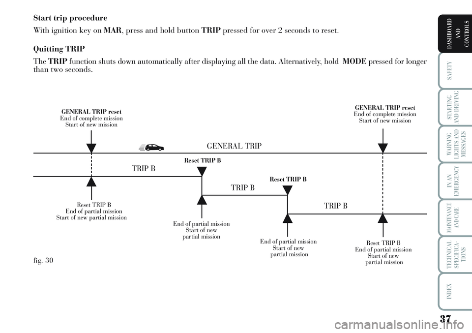
information (as shown in fig. 30).
Page 38 of 218
37
SAFETY
STARTING
AND DRIVING
WARNING
LIGHTS AND
MESSAGES
IN AN
EMERGENCY
MAINTENANCE
AND CARE
TECHNICAL
SPECIFICA-
TIONS
INDEX
DASHBOARD
AND
CONTROLS
Start trip procedure
With ignition key on MAR, press and hold button TRIPpressed for over 2 seconds to reset.
Quitting TRIP
TheTRIPfunction shuts down automatically after displaying all the data. Alternatively, hold MODEpressed for longer
than two seconds.
Reset TRIP B
End of partial mission
Start of new partial mission
End of partial mission
Start of new
partial mission
Reset TRIP B
End of partial mission
Start of new
partial mission GENERAL TRIP reset
End of complete mission
Start of new mission GENERAL TRIP reset
End of complete mission
Start of new mission
End of partial mission
Start of new
partial mission Reset TRIP B
Reset TRIP B
TRIP B
TRIP B
TRIP B GENERAL TRIP
˙
˙
˙
˙
˙
˙˙
˙
fig. 30
Page 95 of 218
94
SAFETY
STARTING
AND DRIVING
WARNING
LIGHTS AND
MESSAGES
IN AN
EMERGENCY
MAINTENANCE
AND CARE
TECHNICAL
SPECIFICA-
TIONS
INDEX
DASHBOARD
AND
CONTROLS
late how much particulates has been
trapped by the filter. Since this filter
physically traps particulate, it should
be regenerated (cleaned) at regular in-
tervals by burning carbon particles.
The regeneration procedure is con-
trolled automatically by the engine
management control unit according to
the filter conditions and vehicle use
conditions. The following phenomena
may occur during the regeneration:
limited increase of idle speed, activation
of electric fan, limited increase of
smoke, high temperatures at the ex-
haust. These are not faults; they do not
impair vehicle performance or damage
the environment. If the dedicated mes-
sage is displayed, refer to section
“Warning lights and messages”.PROTECTING THE
ENVIRONMENT
The devices for curtailing petrol engine
emissions are the following:
❒three-way catalytic converter;
❒Lambda sensor;
❒fuel evaporation system.
In addition, do not let the engine run,
even for a test, with one or more spark
plugs disconnected.
The devices for reducing diesel fuel en-
gine emissions are the following:
❒oxidising catalytic converter;
❒exhaust gas recirculation system
(E.G.R.);
❒diesel particulate filter (DPF)
DPF (DIESEL PARTICULATE
FILTER)
(for 1.3 Multijet 90 HP - 1.3 Multijet
95 HP versions)
The Diesel Particulate Filter is a me-
chanical filter, integral with the exhaust
system, that physically traps particu-
lates present in the exhaust gases of
Diesel engines. The diesel particular fil-
ter has been adopted to eliminate al-
most totally particulates in compliance
with current / future law regulations.
During normal use of the vehicle, the
engine control unit records a set of data
(e.g.: travel time, type of route, tem-
peratures, etc.) and it will then calcu- When refuelling, fasten the cap to the
device inside the flap as shown in the
diagram.
IMPORTANT The airtight sealing of
the tank may cause a slight vacuum.
A suction noise when you release the
cap is therefore entirely normal.
After refuelling, fasten the cap by
turning it clockwise until you hear it
click, then turn the key clockwise ad
remove the key from the flap.
Do not approach naked
flames or lit cigarettes to
the fuel filler: fire risk. Keep your
face away from the fuel filler to
prevent breathing in harmful
vapours.
WARNING
The catalytic converter de-
velops high temperature
during operation. Do not park on
grass, dry leaves, pine needles or
other flammable material: fire
risk.
WARNING
Page 103 of 218
102
STARTING
AND DRIVING
WARNING
LIGHTS AND
MESSAGES
IN AN
EMERGENCY
MAINTENANCE
AND CARE
TECHNICAL
SPECIFICA-
TIONS
INDEX
DASHBOARD
AND
CONTROLS
SAFETY
The research results in relation to the
best protection for children is illus-
trated in European Regulation EEC-
R44 which divides the restraint sys-
tems into five groups in addition to
making their use compulsory:
Group 0 up to 10 kg of weight
Group 0+ up to 13 kg of weight
Group 1 9-18 kg of weight
Group 2 15-25 kg of weight
Group 3 22-36 kg of weight
As it may be noted, the groups over-
lap partly and in fact, there are de-
vices that cover more than one weight
group.
All child restraint devices must bear
the certification data, together with
the control brand, on a solidly fixed
label which must absolutely never be
removed.
When over 1.50 m in height, from the
point of view of restraint systems,
children are considered as adults and
have to wear the standard seat belts.
Lineaccessori Lancia includes child
restraint systems for each weight
group. These devices are recom-
mended having been specifically de-
signed for Lancia cars.
SEVERE DANGER: Do
not arrange child seats
facing backwards on the front seat
if the passenger’s airbag is en-
abled. Deployment of the airbag in
an accident could cause fatal in-
juries to the baby. It is advisable to
carry children on the rear seat,
which is the most protected posi-
tion in the event of an accident.
Child seats must not be fitted on
the front seat of cars fitted with a
passenger air bag, whose deploy-
ment in an accident could cause fa-
tal injuries to the baby regardless
of the seriousness of the impact.
WARNING
In case of need, the pas-
senger airbag can be de-
activated and children can
be place on the front seat.
It is very important to
check that the airbag has
been deactivated by means of the
amber warning light (see the chap-
ter on first and side airbags,
specifically the paragraph on pas-
senger front airbags). Move the
passenger’s seat as far back as
possible to avoid contact between
the child seat and the dashboard.
WARNING
Page 188 of 218
TECHNICAL SPECIFICATIONS
IDENTIFICATION DATA .................................. 188
ENGINE CODES -
BODYWORK VERSIONS.................................. 190
ENGINE........................................................... 191
FUEL FEED .................................................... 192
TRANSMISSION .............................................. 192
BRAKES........................................................... 193
SUSPENSIONS ................................................. 193
STEERING SYSTEM ........................................ 193
WHEELS .......................................................... 194
DIMENSIONS ................................................... 198
PERFORMANCE.............................................. 199
WEIGHTS........................................................ 200
CAPACITIES .................................................... 201
FLUIDS AND LUBRICANTS ............................ 202
FUEL CONSUMPTION.................................... 204
CO
2EMISSIONS ............................................... 205
187
WARNING
LIGHTS AND
MESSAGES
INDEX
DASHBOARD
AND
CONTROLS
SAFETY
STARTING
AND DRIVING
IN AN
EMERGENCY
MAINTENANCE
AND CARE
TECHNICAL
SPECIFICA-
TIONS
Page 189 of 218

IDENTIFICATION
DATA
Take note of the identification codes.
The identification data are printed on
labelsfig. 1in the following positions:
1- Model plate
2- Chassis marking.
3- Bodywork paint identification
plate.
4 - Engine marking.MODEL PLATE fig. 2
This plate is fitted to the engine com-
partment front crossmember and con-
tains the following data:
B- Type approval number.
C- Vehicle type code.
D- Chassis number.
E- Maximum vehicle weight fully
loaded.
F- Maximum vehicle weight fully
loaded with trailer.G- Maximum vehicle weight on front
axle.
H- Maximum vehicle weight on rear
axle.
I- Engine type.
L- Body version code.
M- Spare part code.
N- Smoke opacity index (for diesel
engines).
fig. 1L0D0450mfig. 2L0D0415m
188
WARNING
LIGHTS AND
MESSAGES
INDEX
DASHBOARD
AND
CONTROLS
SAFETY
STARTING
AND DRIVING
IN AN
EMERGENCY
MAINTENANCE
AND CARE
TECHNICAL
SPECIFICA-
TIONS
Page 190 of 218

CHASSIS MARKING fig. 3
This is printed on the passenger com-
partment floor bed near the front
right seat.
The label can be accessed by lifting
the window in the mat and comprises:
❒vehicle model;
❒the chassis progressive number.
BODYWORK PAINT
IDENTIFICATION PLATE fig. 4
This plate is applied to the bonnet
and shows the following data:
A- Paint manufacturer.
B- Colour name.
C- Lancia colour code.
D- Respray and touch up code.ENGINE MARKING
It is stamped onto the cylinder block
(passenger compartment side) and
shows the type and the serial number.
fig. 3L0D0227m
fig. 4L0D0228m
189
WARNING
LIGHTS AND
MESSAGES
INDEX
DASHBOARD
AND
CONTROLS
SAFETY
STARTING
AND DRIVING
IN AN
EMERGENCY
MAINTENANCE
AND CARE
TECHNICAL
SPECIFICA-
TIONS
Page 195 of 218
WHEELS
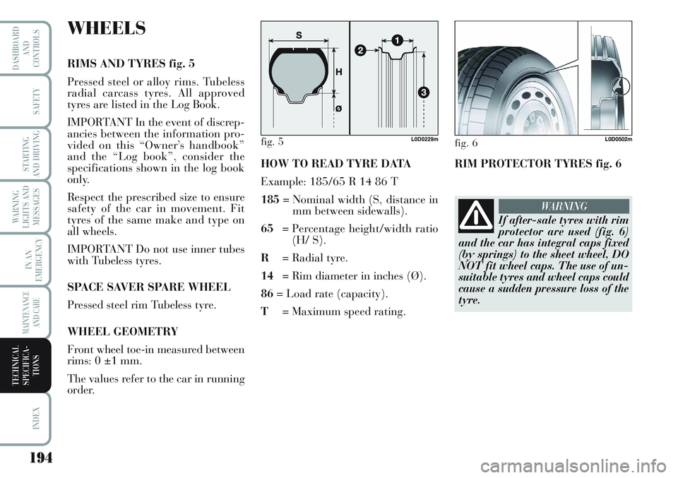
RIMS AND TYRES fig. 5
Pressed steel or alloy rims. Tubeless
radial carcass tyres. All approved
tyres are listed in the Log Book.
IMPORTANT In the event of discrep-
ancies between the information pro-
vided on this “Owner’s handbook”
and the “Log book”, consider the
specifications shown in the log book
only.
Respect the prescribed size to ensure
safety of the car in movement. Fit
tyres of the same make and type on
all wheels.
IMPORTANT Do not use inner tubes
with Tubeless tyres.
SPACE SAVER SPARE WHEEL
Pressed steel rim Tubeless tyre.
WHEEL GEOMETRY
Front wheel toe-in measured between
rims: 0 ±1 mm.
The values refer to the car in running
order.HOW TO READ TYRE DATA
Example: 185/65 R 14 86 T
185= Nominal width (S, distance in
mm between sidewalls).
65= Percentage height/width ratio
(H/ S).
R= Radial tyre.
14= Rim diameter in inches (Ø).
86= Load rate (capacity).
T= Maximum speed rating.
fig. 5L0D0229m
194
WARNING
LIGHTS AND
MESSAGES
INDEX
DASHBOARD
AND
CONTROLS
SAFETY
STARTING
AND DRIVING
IN AN
EMERGENCY
MAINTENANCE
AND CARE
TECHNICAL
SPECIFICA-
TIONS
If after-sale tyres with rim
protector are used (fig. 6)
and the car has integral caps fixed
(by springs) to the sheet wheel, DO
NOT fit wheel caps. The use of un-
suitable tyres and wheel caps could
cause a sudden pressure loss of the
tyre.
WARNING
fig. 6L0D0502m
RIM PROTECTOR TYRES fig. 6
Page 196 of 218

Load rating (capacity)
60 = 250 kg 84 = 500 kg
61 = 257 kg 85 = 515 kg
62 = 265 kg 86 = 530 kg
63 = 272 kg 87 = 545 kg
64 = 280 kg 88 = 560 kg
65 = 290 kg 89 = 580 kg
66 = 300 kg 90 = 600 kg
67 = 307 kg 91 = 615 kg
68 = 315 kg 92 = 630 kg
69 = 325 kg 93 = 650 kg
70 = 335 kg 94 = 670 kg
71 = 345 kg 95 = 690 kg
72 = 355 kg 96 = 710 kg
73 = 365 kg 97 = 730 kg
74 = 375 kg 98 = 750 kg
75 = 387 kg 99 = 775 kg
76 = 400 kg 100 = 800 kg
77 = 412 kg 101 = 825 kg
78 = 425 kg 102 = 850 kg
79 = 437 kg 103 = 875 kg
80 = 450 kg 104 = 900 kg
81 = 462 kg 105 = 925 kg
82 = 475 kg 106 = 950 kg
83 = 487 kgMaximum speed rating
Q = up to 160 km/h.
R = up to 170 km/h.
S = up to 180 km/h.
T = up to 190 km/h.
U = up to 200 km/h.
H = up to 210 km/h.
V = up to 240 km/h.
W = up to 270 km/h.
Y = up to 300 km/h.HOW TO READ THE RIM DATA
Example:6 J x 14 ET 40
6= rim diameter in inches (1).
J= rim drop centre outline (side
projection where the tyre bead
rests) (2).
14= rim nominal diameter in
inches (corresponds to diame-
ter of the tyre to be mounted)
(3 = Ø).
ET= shape and number of humps
(used for withholding tubeless
tyre beads on the rim).
40= wheel camber angle (distance
between the disc/rim support-
ing plane and the wheel rim
centre line).
195
WARNING
LIGHTS AND
MESSAGES
INDEX
DASHBOARD
AND
CONTROLS
SAFETY
STARTING
AND DRIVING
IN AN
EMERGENCY
MAINTENANCE
AND CARE
TECHNICAL
SPECIFICA-
TIONS