turn signal Lancia Thema 2012 Owner handbook (in English)
[x] Cancel search | Manufacturer: LANCIA, Model Year: 2012, Model line: Thema, Model: Lancia Thema 2012Pages: 316, PDF Size: 3.85 MB
Page 74 of 316
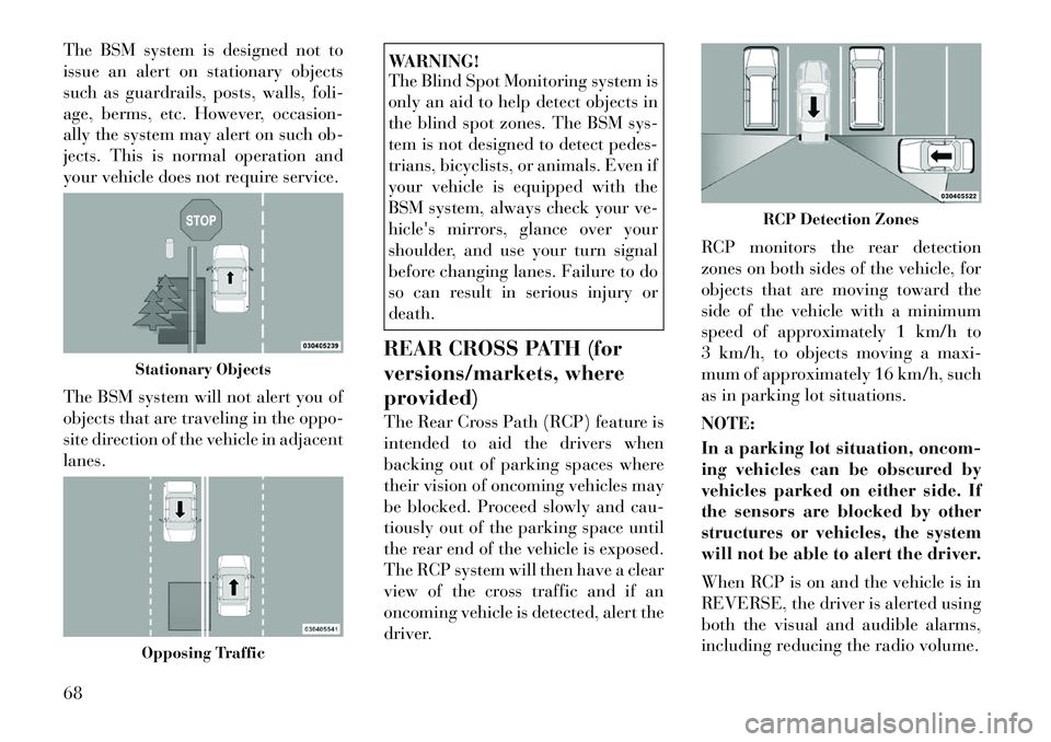
The BSM system is designed not to
issue an alert on stationary objects
such as guardrails, posts, walls, foli-
age, berms, etc. However, occasion-
ally the system may alert on such ob-
jects. This is normal operation and
your vehicle does not require service.
The BSM system will not alert you of
objects that are traveling in the oppo-
site direction of the vehicle in adjacent
lanes.
WARNING!
The Blind Spot Monitoring system is
only an aid to help detect objects in
the blind spot zones. The BSM sys-
tem is not designed to detect pedes-
trians, bicyclists, or animals. Even if
your vehicle is equipped with the
BSM system, always check your ve-
hicle's mirrors, glance over your
shoulder, and use your turn signal
before changing lanes. Failure to do
so can result in serious injury or
death.
REAR CROSS PATH (for
versions/markets, where
provided)
The Rear Cross Path (RCP) feature is
intended to aid the drivers when
backing out of parking spaces where
their vision of oncoming vehicles may
be blocked. Proceed slowly and cau-
tiously out of the parking space until
the rear end of the vehicle is exposed.
The RCP system will then have a clear
view of the cross traffic and if an
oncoming vehicle is detected, alert the
driver. RCP monitors the rear detection
zones on both sides of the vehicle, for
objects that are moving toward the
side of the vehicle with a minimum
speed of approximately 1 km/h to
3 km/h, to objects moving a maxi-
mum of approximately 16 km/h, such
as in parking lot situations.
NOTE:
In a parking lot situation, oncom-
ing vehicles can be obscured by
vehicles parked on either side. If
the sensors are blocked by other
structures or vehicles, the system
will not be able to alert the driver.
When RCP is on and the vehicle is in
REVERSE, the driver is alerted using
both the visual and audible alarms,
including reducing the radio volume.
Stationary ObjectsOpposing Traffic
RCP Detection Zones
68
Page 75 of 316
WARNING!
RCP is not a Back Up Aid system. It
is intended to be used to help a
driver detect an oncoming vehicle in
a parking lot situation. Drivers must
be careful when backing up, even
when using RCP. Always check care-
fully behind your vehicle, look be-
hind you, and be sure to check for
pedestrians, animals, other vehicles,
obstructions, and blind spots before
backing up. Failure to do so can
result in serious injury or death.
MODES OF OPERATION
Three selectable modes of operation
are available in the Uconnect Touch™
System. Refer to “Uconnect Touch™
Settings” in “Understanding Your In-
strument Panel” for further informa-
tion. Blind Spot Alert
When operating in Blind Spot Alert
mode, the BSM system will provide a
visual alert in the appropriate side
view mirror based on a detected ob-
ject. However, when the system is op-
erating in RCP, the system will re-
spond with both visual and audible
alerts when a detected object is pres-
ent. Whenever an audible alert is re-
quested, the radio volume is reduced.
Blind Spot Alert Lights/Chime
When operating in Blind Spot Alert
Lights/Chime mode, the BSM system
will provide a visual alert in the ap-
propriate side view mirror based on a
detected object. If the turn signal is
then activated, and it corresponds to
an alert present on that side of the
vehicle, an audible chime will also be
sounded. Whenever a turn signal and
detected object are present on the
same side at the same time, both the
visual and audio alerts will be issued.
In addition to the audible alert, the
radio (if on) volume will be reduced.NOTE:
Whenever an audible alert is re-
quested by the BSM system, the
radio volume is reduced.
If the hazard flashers are on, the system will request the appro-
priate visual alert only.
When the system is in RCP, the
system shall respond with both vi-
sual and audible alerts when a de-
tected object is present. Whenever
an audible alert is requested, the
radio is also muted. Turn/hazard
signal status is ignored; the RCP
state always requests the audible
chime.
Blind Spot Alert Off
When the BSM system is turned off,
there will be no visual or audible
alerts from either the BSM or RCP
systems.
NOTE:
The BSM system will store the cur-
rent operating mode when the ve-
hicle is shut off. Each time the ve-
hicle is started, the previously
stored mode will be recalled and
used.
69
Page 77 of 316
WARNING!
Any voice commanded system
should be used only in safe driving
conditions following local laws and
phone use. All attention should be
kept on the roadway ahead. Failure
to do so may result in an accident
causing serious injury or death.
The Uconnect™ Phone is driven
through your Bluetooth® “Hands-
Free Profile” mobile phone.
Uconnect™ features Bluetooth®
technology - the global standard that
enables different electronic devices to
connect to each other without wires or
a docking station, so Uconnect™
Phone works no matter where you
stow your mobile phone (be it your
purse, pocket, or briefcase), as long as
your phone is turned on and has been
paired to the vehicle's Uconnect™
Phone. The Uconnect™ Phone allows
up to ten mobile phones or audio de-
vices to be linked to the system. Only
one linked (or paired) mobile phone
and one audio device can be used with the system at a time. The system is
available in English, Spanish, or
French languages.
Uconnect™ Phone Button
The Uconnect™ Phone
Button is used to get into
the phone mode and make
calls, show recent, incom-
ing, outgoing calls, view phonebook
etc., When you press the button you
will hear a BEEP. The beep is your
signal to give a command.
Uconnect™ Voice Command Button The Uconnect™ Voice
Command
Button is
only used for “barge in”
and when you are already in
a call and you want to send Tones or
make another call.
The
button is also used to access
the Voice Commands for the
Uconnect™ Voice Command features
if your vehicle is equipped. Please see
the Uconnect™ Voice Command sec-
tion for direction on how to use the
button.
The Uconnect™ Phone is fully inte-
grated with the vehicle's audio sys- tem. The volume of the Uconnect™
Phone can be adjusted either from the
radio volume control knob or from the
steering wheel radio control (right
switch), if so equipped.
OPERATION
Voice commands can be used to oper-
ate the Uconnect™ Phone and to
navigate through the Uconnect™
Phone menu structure. Voice com-
mands are required after most
Uconnect™ Phone prompts. There
are two general methods for how
Voice Command works:
1. Say compound commands like
“Call John Smith mobile”.
2. Say the individual commands and
allow the system to guide you to com-
plete the task.
You will be prompted for a specific
command and then guided through
the available options.
Prior to giving a voice command,
one must wait for the beep, which
follows the “Listen” prompt or an-
other prompt.
71
Page 112 of 316

“Understanding Your Instru-
ment Panel” for further infor-
mation.
SMARTBEAM™
The SmartBeam™ system provides
increased forward lighting at night by
automating high beam control
through the use of a digital camera
mounted on the inside rearview mir-
ror. This camera detects vehicle spe-
cific light and automatically switches
from high beams to low beams until
the approaching vehicle is out of view.
NOTE:
SmartBeam™ can be turned on or off using the Uconnect
Touch™ System, refer to
“Uconnect Touch™ Settings” in
“Understanding Your Instru-
ment Panel” for further infor-
mation.
Broken, muddy, or obstructed headlights and taillights of ve-
hicles in the field of view will
cause headlights to remain on
longer (closer to the vehicle).
Also, dirt, film, and other ob-
structions on the windshield or camera lens will cause the sys-
tem to function improperly.
DAYTIME RUNNING
LIGHTS (DRLs)
DRLs come ON when the vehicle is
running and shifted out of park, the
headlights are OFF and the parking
brake is OFF. The headlight switch
must be used for normal nighttime
driving. If a turn signal is activated,
the DRL lamp on the same side of the
vehicle will turn off for the duration of
the turn signal activation. Once the
turn signal is no longer active, the
DRL lamp will illuminate.
NOTE:
Depending on your area's regula-
tions, DRLs may be able to be
turned on and off. The DRLs can
be turned on and off using the
Uconnect Touch™ System, refer to
“Uconnect Touch™ Settings” in
“Understanding Your Instrument
Panel” for further information. ADAPTIVE BI-XENON
HIGH INTENSITY
DISCHARGE HEADLIGHTS
(for versions/markets,
where provided)
This system automatically swivels the
headlight beam pattern horizontally
to provide increased illumination in
the direction the vehicle is steering.
NOTE:
Each time the Adaptive Head-
light System is turned on, the
headlights will initialize by per-
forming a brief sequence of rota-
tions.
The Adaptive Headlight System is active only when the vehicle is
moving forward.
The Adaptive Headlight System
can be turned On or Off using the
Uconnect Touch™ System, refer to
“Uconnect Touch™ Settings” in
“Understanding Your Instrument
Panel” for further information.
106
Page 113 of 316
LIGHTS-ON REMINDER
If the headlights or parking lights are
on after the ignition is placed in the
OFF position, a chime will sound to
alert the driver when the driver's door
is opened.
FOG LIGHTSThe fog light switch is built
into the headlight switch.
To activate the fog lights,
turn the headlamp switch to
the park lamp or headlamp position.
Press the headlight switch once for
front fog lights, press the switch a
second time for front and rear fog
lights. Pressing the switch a third time
will deactivate the rear fog lights, and
a fourth time will deactivate the front
fog lights. Turning the headlight
switch off will also deactivate the fog
lights.
An indicator light in the instrument
cluster illuminates when the fog lights
are turned on.
NOTE:
The front fog lights will activate
automatically when turning on the
position lights or the low beam headlights if previously deacti-
vated by turning the headlight
switch off. The rear fog lights will
only turn on by operating the
switch as previously described.
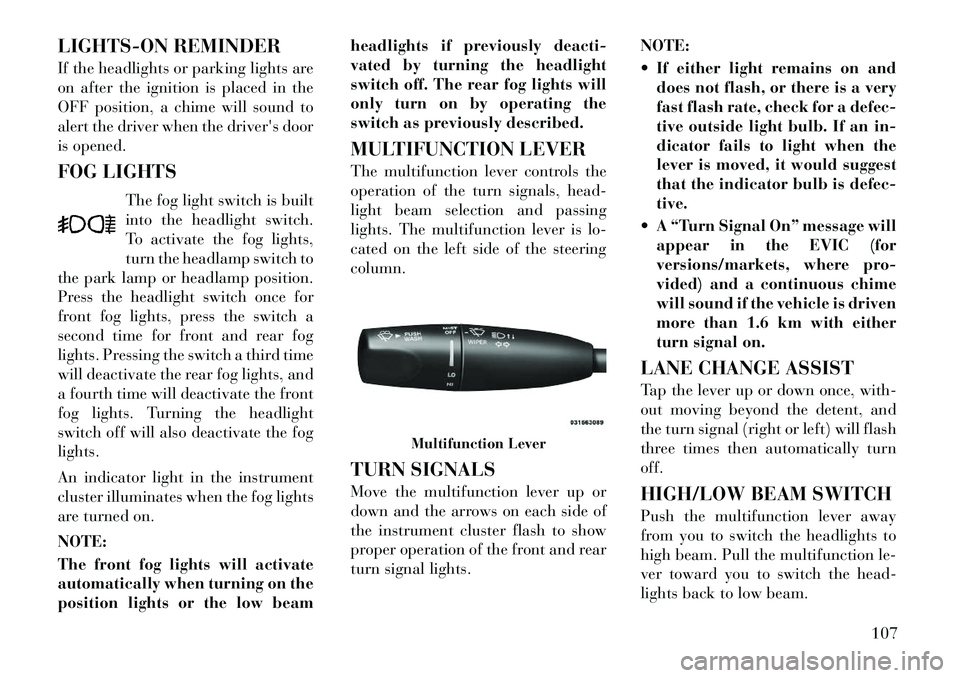
MULTIFUNCTION LEVER
The multifunction lever controls the
operation of the turn signals, head-
light beam selection and passing
lights. The multifunction lever is lo-
cated on the left side of the steering
column.
TURN SIGNALS
Move the multifunction lever up or
down and the arrows on each side of
the instrument cluster flash to show
proper operation of the front and rear
turn signal lights.
NOTE:
If either light remains on and
does not flash, or there is a very
fast flash rate, check for a defec-
tive outside light bulb. If an in-
dicator fails to light when the
lever is moved, it would suggest
that the indicator bulb is defec-
tive.
A “Turn Signal On” message will appear in the EVIC (for
versions/markets, where pro-
vided) and a continuous chime
will sound if the vehicle is driven
more than 1.6 km with either
turn signal on.
LANE CHANGE ASSIST
Tap the lever up or down once, with-
out moving beyond the detent, and
the turn signal (right or left) will flash
three times then automatically turn
off.
HIGH/LOW BEAM SWITCH
Push the multifunction lever away
from you to switch the headlights to
high beam. Pull the multifunction le-
ver toward you to switch the head-
lights back to low beam.
Multifunction Lever
107
Page 114 of 316

FLASH-TO-PASS
You can signal another vehicle with
your headlights by lightly pulling the
multifunction lever toward you. This
will turn on the high beams headlights
until the lever is released.
COURTESY LIGHTS
The courtesy lights can be turned on
by pressing the top corner of the lens.
To turn the lights off, press the lens a
second time.FRONT MAP/READING
LIGHTS
The front map/reading lights can be
turned on by pressing a switch on
either side of the console. These
switches are backlit for night time
visibility. To turn the lights off, press
the switch a second time. The lightswill also turn on when the UNLOCK
button on the Remote Keyless Entry
(RKE) is pressed.
AMBIENT LIGHT
The overhead console is equipped
with an ambient light feature. This
light casts illumination for improved
visibility of the floor center console
and PRNDL area.
INTERIOR LIGHTS
The interior lights come on when a
door is opened.
To protect the battery, the interior
lights will turn off automatically
10 minutes after the ignition switch is
moved to the LOCK position. This
will occur if the interior lights were
switched on manually or are on be-
cause a door is open. This includes the
Courtesy Lights
Front Map/Reading Lights
Front Map/Reading Light Switches
Ambient Light
108
Page 160 of 316

INSTRUMENT CLUSTER
DESCRIPTIONS
1. TachometerThis gauge measures engine
revolutions-per-minute (RPM x 1000).2. Park/Headlight ON Indicator
(for versions/markets, where
provided)This indicator will illumi-
nate when the park lights or
headlights are turned on.
3. Turn Signal Indicators The arrow will flash with
the exterior turn signal
when the turn signal lever is
operated.
If the vehicle electronics sense that the
vehicle is driven more than 1.6 km
with either turn signal on, a continu-
ous chime will sound to alert you to
turn the signals off. If either indicator
flashes at a rapid rate, check for a
defective outside light bulb. 4. Front Fog Light Indicator (for
versions/markets, where provided)
This indicator will illuminate
when the front fog lights are on.
5. Rear Fog Light Indicator (for
versions/markets, where provided)
This indicator will illuminate
when the rear fog lights are on.
6. High Beam Indicator
This indicator shows that the
high beam headlights are on.
Push the multifunction lever
forward to switch the headlights to
high beam, and pull toward yourself
(normal position) to return to low
beam.
7. Odometer Display / Electronic
Vehicle Information Center (EVIC)
Display
Odometer Display
The odometer display shows the total
distance the vehicle has been driven. Electronic Vehicle Information
Center (EVIC) Display
The Electronic Vehicle Information
Center (EVIC) features a driver-
interactive display that is located in
the instrument cluster. For further in-
formation, refer to “Electronic Ve-
hicle Information Center (EVIC)”.
The Shift Lever Indicator is self-
contained within the EVIC display. It
displays the gear position of the auto-
matic transmission.
NOTE:
You must apply the brakes be-
fore shifting from PARK.
The highest available transmis-
sion gear is displayed in the
lower right corner of the Elec-
tronic Vehicle Information Cen-
ter (EVIC) whenever the Elec-
tronic Range Select (ERS)
feature is active. Use the +/- se-
lector on the shift lever to acti-
vate ERS. Refer to “Automatic
Transmission” in “Starting And
Operating” for further informa-
tion.
154
Page 167 of 316

sages of this type are then stored (as
long as the condition that activated
it remains active) and can be re-
viewed from the "Messages" main
menu item. As long as there is a
stored message, an "i" will be dis-
played in theEVIC's compass/
outside temp line. Examples of this
message type are "Right Front Turn
Signal Lamp Out" and "Low Tire
Pressure".
Unstored Messages
This message type is displayed indefi-
nitely or until the condition that acti-
vated the message is cleared. Ex-
amples of this message type are "Turn
Signal On" (if a turn signal is left on)
and "Lights On" (if driver leaves the
vehicle).
Unstored Messages Until RUN
This message type is displayed until
the ignition is in the RUN state. An
example of this message type is "Press
Brake Pedal and Push Button to
Start". Five Second Unstored Messages
When the appropriate conditions oc-
cur, this type of message takes control
of the main display area for five sec-
onds and then returns to the previous
screen. Examples of this message type
are "Memory System Unavailable -
Not in Park" and "Automatic High
Beams On".
The Reconfigurable Telltales section
is divided into the white telltales area
on the right, amber telltales in the
middle, and red telltales on the left.
EVIC WHITE TELLTALES
This area will show reconfigurable
white caution telltales. These telltales
include:
Shift Lever Status — Diesel Only
The selected AutoStick gear is dis-
played as D1, D2, D3, D4, D5 and
indicate the Electronic Range Select
(ERS) feature has been engaged and
the gear selected is displayed. For fur-
ther information on Autostick, refer
to “Starting And Operating”. Electronic Speed Control ON
This telltale will illuminate
when the electronic speed
control is ON. For further
information, refer to “Elec-
tronic Speed Control” in “Under-
standing The Features Of Your Ve-
hicle.”
Electronic Speed Control SET This telltale will illuminate
when the electronic speed
control is SET. For further
information, refer to “Elec-
tronic Speed Control” in “Under-
standing The Features Of Your Ve-
hicle.”
Adaptive Cruise Control (ACC) ON This telltale will illuminate
when the ACC is ON. For
further information, refer
to “Adaptive Cruise Control
(ACC)” in “Understanding The Fea-
tures Of Your Vehicle.”
161
Page 177 of 316
warns you of a possible collision when
you are much closer to the vehicle in
front of you. This allows for a more
dynamic driving experience. To
change the FCW status, touch and
release the OFF, Near or Far button.
Then touch the arrow back soft-key.
For further information, refer to
“Adaptive Cruise Control (ACC)” in
“Understanding The Features Of
Your Vehicle”.
Park Assist (for versions/markets, where provided)
The Rear Park Assist system will scan
for objects behind the vehicle when
the transmission shift lever is in RE-
VERSE and the vehicle speed is less
than 11 mph (18 km/h). The system
can be enabled with Sound Only,
Sound and Display, or turned OFF. To
change the Park Assist status, touch
and release the OFF, Sound Only or
Sounds and Display button. Then
touch the arrow back soft-key. Refer
to “ParkSense® Rear Park Assist” in
“Understanding The Features Of
Your Vehicle” for system function and
operating information. Tilt Mirrors In Reverse (for
versions/markets, where
provided)
When this feature is selected, the out-
side sideview mirrors will tilt down-
ward when the ignition is in the RUN
position and the transmission shift le-
ver is in the REVERSE position. The
mirrors will move back to their previ-
ous position when the transmission is
shifted out of REVERSE. To make
your selection, touch the Tilt Mirrors
In Reverse soft-key, until a check-
mark appears next to setting, showing
that setting has been selected. Touch
the back arrow soft-key to return to
the previous menu.
Blind Spot Alert (for versions/markets, where
provided)
When this feature is selected, the
Blind Spot Alert feature can be set to
Off, Lights or Lights and Chime. The
Blind Spot Alert feature can be acti-
vated in “Lights” mode. When this
mode is selected, the Blind Spot Moni-
tor (BSM) system is activated and will
only show a visual alert in the outside
mirrors. When “Lights & Chime” mode is activated, the Blind Spot
Monitor (BSM) will show a visual
alert in the outside mirrors as well as
an audible alert when the turn signal
is on. When “Off” is selected, the
Blind Spot Monitor (BSM) system is
deactivated. To change the Blind Spot
Alert status, touch the Off, Lights or
Lights & Chime soft-key. Then touch
the arrow back soft-key.
NOTE:
If your vehicle has experienced
any damage in the area where the
sensor is located, even if the fascia
is not damaged, the sensor may
have become misaligned. Take
your vehicle to an authorized
dealer to verify sensor alignment.
Having a sensor that is misaligned
will result in the BSM not operat-
ing to specification.
171
Page 215 of 316

WARNING!(Continued)
The ABS cannot prevent colli-
sions, including those resulting
from excessive speed in turns, fol-
lowing another vehicle too closely,
or hydroplaning.
The capabilities of an ABS
equipped vehicle must never be ex-
ploited in a reckless or dangerous
manner that could jeopardize the
user's safety or the safety of others.
All vehicle wheels and tires must be
the same size and type and tires must
be properly inflated to produce accu-
rate signals for the computer.
ELECTRONIC BRAKE
CONTROL SYSTEM
Your vehicle is equipped with an ad-
vanced electronic brake control sys-
tem that include Anti-Lock Brake
System (ABS), Traction Control Sys-
tem (TCS), Brake Assist System
(BAS), and the Electronic Stability
Control (ESC). All four of these sys-
tems work together to enhance vehicle
stability and control in various driv-
ing conditions. Also, your vehicle is equipped with
Hill Start Assist (HSA), Ready Alert
Braking, and Rain Brake Support.
ANTI-LOCK BRAKE
SYSTEM (ABS)
This system aids the driver in main-
taining vehicle control under adverse
braking conditions by controlling hy-
draulic brake pressure. This prevents
wheel lock-up to help avoid skidding
on slippery surfaces during braking.
Refer to “Anti-Lock Brake System” in
“Starting and Operating” for further
information.
WARNING!
The ABS cannot prevent the natural
laws of physics from acting on the
vehicle, nor can it increase the trac-
tion afforded by prevailing road
conditions. The ABS cannot prevent
collisions, including those resulting
from excessive speed in turns, driv-
ing on very slippery surfaces, or hy-
droplaning. The capabilities of an
ABS-equipped vehicle must never be
exploited in a reckless or dangerous
manner that could jeopardize the us-
er's safety or the safety of others.
TRACTION CONTROL
SYSTEM (TCS)
This system monitors the amount of
wheel spin of each driven wheel. If
wheel spin is detected, brake pressure
is applied to the slipping wheel(s) and
engine power is reduced to provide
enhanced acceleration and stability.
BRAKE ASSIST SYSTEM
(BAS)
This system complements the ABS by
optimizing the vehicle braking
capa-
bility during emergency brake ma-
neuvers. This system detects an emer-
gency braking situation by sensing
the rate and amount of brake applica-
tion and then applies optimum pres-
sure to the brakes. This can help re-
duce braking distances.
Applying the brakes very quickly re-
sults in the best BAS assistance. To
receive the benefits of this system, you
must apply continuous brake pedal
pressure during the stopping se-
quence. Do not reduce brake pedal
pressure unless braking is no longer
desired. Once the brake pedal is re-
leased, the BAS is deactivated.
209