brake light Lancia Thema 2012 Owner handbook (in English)
[x] Cancel search | Manufacturer: LANCIA, Model Year: 2012, Model line: Thema, Model: Lancia Thema 2012Pages: 316, PDF Size: 3.85 MB
Page 19 of 316
IGNITION OR ACCESSORY
ON MESSAGE
Opening the driver's door when the
ignition is in ACC or ON (engine not
running), a chime will sound to re-
mind you to cycle the ignition to OFF.
In addition to the chime, the ignition
or accessory on message will display
in the cluster.
NOTE:
With the Uconnect Touch™ sys-
tem, the power window switches,
radio, power sunroof (for versions/
markets, where provided), and
power outlets will remain active
for up to 10 minutes after the igni-
tion is cycled to the OFF position.
Opening either front door will can-
cel this feature. The time for this
feature is programmable. Refer to
“Uconnect Touch™ Settings” in
“Understanding Your Instrument
Panel” for further information.
WARNING!
When leaving the vehicle, alwaysremove the key fob and lock your
vehicle.
Never leave children alone in a
vehicle, or with access to an un-
locked vehicle.
Allowing children to be in a ve-
hicle unattended is dangerous for
a number of reasons. A child or
others could be seriously or fatally
injured. Children should be
warned not to touch the parking
brake, brake pedal or the shift
lever.
Do not leave the key fob in or near
the vehicle, and do not leave Key-
less Enter-N-Go in the ACC or
ON/RUN mode. A child could op-
erate power windows, other con-
trols, or move the vehicle.
Do not leave children or animals
inside parked vehicles in hot
weather. Interior heat build-up
may cause serious injury or death.
CAUTION!
An unlocked car is an invitation to
thieves. Always remove the Key Fob
from vehicle, cycle the ignition OFF
and lock all doors when leaving the
vehicle unattended.
SENTRY KEY®
The Sentry Key® Immobilizer System
prevents unauthorized vehicle opera-
tion by disabling the engine. The sys-
tem does not need to be armed or
activated. Operation is automatic, re-
gardless of whether the vehicle is
locked or unlocked.
The system uses a Key Fob with Re-
mote Keyless Entry (RKE) transmit-
ter, a Keyless Ignition Node (KIN) and
a RF receiver to prevent unauthorized
vehicle operation. Therefore, only
Key Fobs that are programmed to the
vehicle can be used to start and oper-
ate the vehicle.
After placing the ignition in the ON/
RUN position, the Vehicle Security
Light will turn on for three seconds
for a bulb check. If the light remains
on after the bulb check, it indicates
13
Page 58 of 316
Air Bag Warning Light
The light should come on and remain
on for four to eight seconds as a bulb
check when the ignition switch is first
turned ON. If the light is not lit during
starting, see your authorized dealer. If
the light stays on, flickers, or comes
on while driving, have the system
checked by an authorized dealer.
Defroster
Check operation by selecting the de-
frost mode and place the blower con-
trol on high speed. You should be able
to feel the air directed against the
windshield. See your authorized
dealer for service if your defroster is
inoperable.
Floor Mat Safety Information
Always use floor mats designed to fit
the footwell of your vehicle. Use only
floor mats that leave the pedal area
unobstructed and that are firmly se-
cured so that they cannot slip out of
position and interfere with the pedalsor impair safe operation of your ve-
hicle in other ways.
WARNING!
Pedals that cannot move freely can
cause loss of vehicle control and in-
crease the risk of serious personal
injury.
Always make sure that floor mats
are properly attached to the floor
mat fasteners.
Never place or install floor mats or
other floor coverings in the vehicle
that cannot be properly secured to
prevent them from moving and
interfering with the pedals or the
ability to control the vehicle.
Never put floor mats or other floor
coverings on top of already in-
stalled floor mats. Additional
floor mats and other coverings
will reduce the size of the pedal
area and interfere with the pedals.
(Continued)
WARNING!(Continued)
Check mounting of mats on a
regular basis. Always properly re-
install and secure floor mats that
have been removed for cleaning.
Always make sure that objects
cannot fall into the driver footwell
while the vehicle is moving. Ob-
jects can become trapped under
the brake pedal and accelerator
pedal causing a loss of vehicle
control.
If required, mounting posts must
be properly installed, if not
equipped from the factory.
Failure to properly follow floor mat
installation or mounting can cause
interference with the brake pedal
and accelerator pedal operation
causing loss of control of the vehicle.
52
Page 59 of 316

Periodic Safety Checks You
Should Make Outside The
Vehicle
Tires
Examine tires for excessive tread wear
and uneven wear patterns. Check for
stones, nails, glass, or other objects
lodged in the tread or sidewall. In-
spect the tread for cuts and cracks.
Inspect sidewalls for cuts, cracks and
bulges. Check the wheel nuts fortightness. Check the tires (including
spare) for proper cold inflation pres-
sure.
Lights
Have someone observe the operation
of exterior lights while you work the
controls. Check turn signal and high
beam indicator lights on the instru-
ment panel.
Door Latches
Check for positive closing, latching,
and locking.Fluid Leaks
Check area under vehicle after over-
night parking for fuel, engine coolant,
oil, or other fluid leaks. Also, if gaso-
line fumes are detected or if fuel,
power steering fluid, or brake fluid
leaks are suspected, the cause should
be located and corrected immediately.
53
Page 112 of 316

“Understanding Your Instru-
ment Panel” for further infor-
mation.
SMARTBEAM™
The SmartBeam™ system provides
increased forward lighting at night by
automating high beam control
through the use of a digital camera
mounted on the inside rearview mir-
ror. This camera detects vehicle spe-
cific light and automatically switches
from high beams to low beams until
the approaching vehicle is out of view.
NOTE:
SmartBeam™ can be turned on or off using the Uconnect
Touch™ System, refer to
“Uconnect Touch™ Settings” in
“Understanding Your Instru-
ment Panel” for further infor-
mation.
Broken, muddy, or obstructed headlights and taillights of ve-
hicles in the field of view will
cause headlights to remain on
longer (closer to the vehicle).
Also, dirt, film, and other ob-
structions on the windshield or camera lens will cause the sys-
tem to function improperly.
DAYTIME RUNNING
LIGHTS (DRLs)
DRLs come ON when the vehicle is
running and shifted out of park, the
headlights are OFF and the parking
brake is OFF. The headlight switch
must be used for normal nighttime
driving. If a turn signal is activated,
the DRL lamp on the same side of the
vehicle will turn off for the duration of
the turn signal activation. Once the
turn signal is no longer active, the
DRL lamp will illuminate.
NOTE:
Depending on your area's regula-
tions, DRLs may be able to be
turned on and off. The DRLs can
be turned on and off using the
Uconnect Touch™ System, refer to
“Uconnect Touch™ Settings” in
“Understanding Your Instrument
Panel” for further information. ADAPTIVE BI-XENON
HIGH INTENSITY
DISCHARGE HEADLIGHTS
(for versions/markets,
where provided)
This system automatically swivels the
headlight beam pattern horizontally
to provide increased illumination in
the direction the vehicle is steering.
NOTE:
Each time the Adaptive Head-
light System is turned on, the
headlights will initialize by per-
forming a brief sequence of rota-
tions.
The Adaptive Headlight System is active only when the vehicle is
moving forward.
The Adaptive Headlight System
can be turned On or Off using the
Uconnect Touch™ System, refer to
“Uconnect Touch™ Settings” in
“Understanding Your Instrument
Panel” for further information.
106
Page 122 of 316

NOTE:
In order to ensure proper opera-
tion, the Electronic Speed Control
System has been designed to shut
down if multiple Speed Control
functions are operated at the same
time. If this occurs, the Electronic
Speed Control System can be reac-
tivated by pushing the Electronic
Speed Control ON/OFF button and
resetting the desired vehicle set
speed.
TO ACTIVATE
Push the ON/OFF button. The Cruise
Indicator Light in the Electronic Ve-
hicle Information Center (EVIC) will
illuminate. To turn the system off,
push the ON/OFF button a second
time. The Cruise Indicator Light will
turn off. The system should be turned
off when not in use.
WARNING!
Leaving the Electronic Speed Con-
trol system on when not in use is
dangerous. You could accidentally
set the system or cause it to go faster
than you want. You could lose con-
trol and have an accident. Always
leave the system OFF when you are
not using it.
TO SET A DESIRED SPEED
Turn the Electronic Speed Control
ON. When the vehicle has reached the
desired speed, press the SET (-) but-
ton and release. Release the accelera-
tor and the vehicle will operate at the
selected speed.
NOTE:
The vehicle should be traveling at
a steady speed and on level ground
before pressing the SET button.
TO DEACTIVATE
A soft tap on the brake pedal, pushing
the CANCEL button, or normal brake
pressure while slowing the vehicle will
deactivate Electronic Speed Control
without erasing the set speed memory. Pressing the ON/OFF button or turn-
ing the ignition switch OFF erases the
set speed memory.
TO RESUME SPEED
To resume a previously set speed,
push the RES (+) button and release.
Resume can be used at any speed
above 32 km/h.
TO VARY THE SPEED
SETTING
When the Electronic Speed Control is
set, you can increase speed by pushing
the RES (+) button. If the button is
continually pressed, the set speed will
continue to increase until the button is
released, then the new set speed will
be established.
Pressing the RES (+) button once will
result in the following set speeds:
2.0 km/h (3.0L Diesel Engine)
1.6 km/h (3.6L Engine)
Each subsequent tap of the button
results in an increase of 2.0 km/h
(3.0L Diesel Engine) or 1.6 km/h
(3.6L Engine).
116
Page 127 of 316

TO RESUME SPEED
Press the RES+button and release.
Then remove your foot from the ac-
celerator pedal. The EVIC will dis-
play the last set speed.
NOTE:
You can resume ACC from a mini-
mum of 30 km/h.WARNING!
The Resume function should only be
used if traffic and road conditions
permit. Resuming a set speed that is
too high or too low for prevailing
traffic and road conditions could
cause the vehicle to accelerate or
decelerate too sharply for safe op-
eration. Failure to follow these
warnings can result in a collision
and death or serious personal injury.
TO VARY THE SPEED
SETTING
While ACC is set, you can increase the
set speed by pressing and holding the
RES +button. The increase in set
speed is reflected in the EVIC display:
While in US Mode, if the button is
continually pressed, the set speed will continue to increase in 8 km/h incre-
ments. While in Metric Mode, if the
button is continually pressed, the set
speed will continue to increase in
10 km/h increments.
While in US Mode, pressing the RES
+
button once will result in a 1.6 km/h
increase in set speed. Each subse-
quent tap of the button results in in-
crease of 1.6 km/h. While in Metric
Mode, pressing the RES +button once
will result in a 1.0 km/h increase in set
speed. Each subsequent tap of the
button results in increase of 1.0 km/h.
While ACC is set, the set speed can be
decreased by pressing and holding the
SET -button.
If the button is held while in US Mode,
the set speed will continue to decrease
in 8 km/h increments.
If the button is held while in Metric
Mode, the set speed will continue to
decrease in 10 km/h increments.
While in US Mode, pressing the SET -
button once will result in a 1.6 km/h
decrease in set speed. Each subse-
quent tap of the button results in de-
crease of 1.6 km/h. While in Metric Mode, pressing the
SET
-button once will result in a
1.0 km/h decrease in set speed. Each
subsequent tap of the button results in
decrease of 1.0 km/h.
NOTE:
When you use the SET - button
to decelerate, if the engine’s
braking power does not slow the
vehicle sufficiently to reach the
set speed, the brake system will
automatically slow the vehicle.
The ACC system can only apply a maximum of 25% of the vehi-
cle's braking capability and will
not bring the vehicle to a com-
plete stop.
The ACC system maintains set speed when driving up hill and
down hill. However, a slight
speed change on moderate hills
is normal. In addition, down-
shifting may occur while climb-
ing uphill or descending down-
hill. This is normal operation
and necessary to maintain set
speed.
121
Page 128 of 316

SETTING THE
FOLLOWING DISTANCE IN
ACC
The specified following distance for
ACC can be set by varying the dis-
tance setting between 3 (long), 2 (me-
dium), and 1 (short). Using this dis-
tance setting and the vehicle speed,
ACC calculates and sets the distance
to the vehicle ahead. This distance
setting displays in the EVIC.To change the distance setting, press
the Distance button and release. Each
time the button is pressed, the dis-
tance setting adjusts between 3
(long), 2 (medium), and 1 (short).
If there is no vehicle ahead, the vehicle
will maintain the set speed. If a slower
moving vehicle is detected in the same
lane, the EVIC displays the “Sensed
Vehicle Indicator” icon, and the sys-
tem adjusts vehicle speed automati-
cally to maintain the distance setting,
regardless of the set speed.
The vehicle will then maintain the set
distance until:
The vehicle ahead accelerates to a
speed above the set speed.
The vehicle ahead moves out of your lane or view of the sensor. The vehicle ahead slows to a speed
below 24 km/h and the system au-
tomatically disengages itself.
The distance setting is changed.
The system disengages. (Refer to the information on ACC Activa-
tion).
The maximum braking applied by
ACC is limited; however, the driver
can always apply the brakes manu-
ally, if necessary.
NOTE:
The brake lights will illuminate
whenever the ACC system applies
the brakes.
A Proximity Warning will alert the
driver if ACC predicts that its maxi-
mum braking level is not sufficient to
maintain the set distance. If this oc-
curs, a visual alert “BRAKE” will
flash in the EVIC and a chime will
sound while ACC continues to apply
its maximum braking capacity. When
this occurs, you should immediately
apply the brakes as needed to main-
tain a safe distance from the vehicle
ahead.
Distance Set 3 (long)Distance Set 2 (medium)
Distance Set 1 (short)
122
Page 160 of 316

INSTRUMENT CLUSTER
DESCRIPTIONS
1. TachometerThis gauge measures engine
revolutions-per-minute (RPM x 1000).2. Park/Headlight ON Indicator
(for versions/markets, where
provided)This indicator will illumi-
nate when the park lights or
headlights are turned on.
3. Turn Signal Indicators The arrow will flash with
the exterior turn signal
when the turn signal lever is
operated.
If the vehicle electronics sense that the
vehicle is driven more than 1.6 km
with either turn signal on, a continu-
ous chime will sound to alert you to
turn the signals off. If either indicator
flashes at a rapid rate, check for a
defective outside light bulb. 4. Front Fog Light Indicator (for
versions/markets, where provided)
This indicator will illuminate
when the front fog lights are on.
5. Rear Fog Light Indicator (for
versions/markets, where provided)
This indicator will illuminate
when the rear fog lights are on.
6. High Beam Indicator
This indicator shows that the
high beam headlights are on.
Push the multifunction lever
forward to switch the headlights to
high beam, and pull toward yourself
(normal position) to return to low
beam.
7. Odometer Display / Electronic
Vehicle Information Center (EVIC)
Display
Odometer Display
The odometer display shows the total
distance the vehicle has been driven. Electronic Vehicle Information
Center (EVIC) Display
The Electronic Vehicle Information
Center (EVIC) features a driver-
interactive display that is located in
the instrument cluster. For further in-
formation, refer to “Electronic Ve-
hicle Information Center (EVIC)”.
The Shift Lever Indicator is self-
contained within the EVIC display. It
displays the gear position of the auto-
matic transmission.
NOTE:
You must apply the brakes be-
fore shifting from PARK.
The highest available transmis-
sion gear is displayed in the
lower right corner of the Elec-
tronic Vehicle Information Cen-
ter (EVIC) whenever the Elec-
tronic Range Select (ERS)
feature is active. Use the +/- se-
lector on the shift lever to acti-
vate ERS. Refer to “Automatic
Transmission” in “Starting And
Operating” for further informa-
tion.
154
Page 163 of 316

14. Brake Warning LightThis light monitors various
brake functions, including
brake fluid level and park-
ing brake application. If the
brake light turns on it may indicate
that the parking brake is applied, that
the brake fluid level is low, or that
there is a problem with the anti-lock
brake system reservoir.
If the light remains on when the park-
ing brake has been disengaged, and
the fluid level is at the full mark on the
master cylinder reservoir, it indicates
a possible brake hydraulic system
malfunction or that a problem with
the Brake Booster has been detected
by the Anti-Lock Brake System (ABS)
/ Electronic Stability Control (ESC)
system. In this case, the light will re-
main on until the condition has been
corrected. If the problem is related to
the brake booster, the ABS pump will
run when applying the brake and a
brake pedal pulsation may be felt dur-
ing each stop.
The dual brake system provides a re-
serve braking capacity in the event of
a failure to a portion of the hydraulic system. A leak in either half of the
dual brake system is indicated by the
Brake Warning Light, which will turn
on when the brake fluid level in the
master cylinder has dropped below a
specified level.
The light will remain on until the
cause is corrected.
NOTE:
The light may flash momentarily
during sharp cornering maneu-
vers, which change fluid level con-
ditions. The vehicle should have
service performed, and the brake
fluid level checked.
If brake failure is indicated, immedi-
ate repair is necessary.
WARNING!
Driving a vehicle with the red brake
light on is dangerous. Part of the
brake system may have failed. It will
take longer to stop the vehicle. You
could have a collision. Have the ve-
hicle checked immediately.
Vehicles equipped with the Anti-Lock
Brake System (ABS), are also
equipped with Electronic Brake Force Distribution (EBD). In the event of an
EBD failure, the Brake Warning Light
will turn on along with the ABS Light.
Immediate repair to the ABS system is
required.
Operation of the Brake Warning Light
can be checked by turning the ignition
switch from the OFF position to the
ON/RUN position. The light should
illuminate for approximately two sec-
onds. The light should then turn off
unless the parking brake is applied or
a brake fault is detected. If the light
does not illuminate, have the light
inspected by an authorized dealer.
The light also will turn on when the
parking brake is applied with the ig-
nition switch in the ON/RUN posi-
tion.
NOTE:
This light shows only that the
parking brake is applied. It does
not show the degree of brake ap-
plication.
157
Page 164 of 316
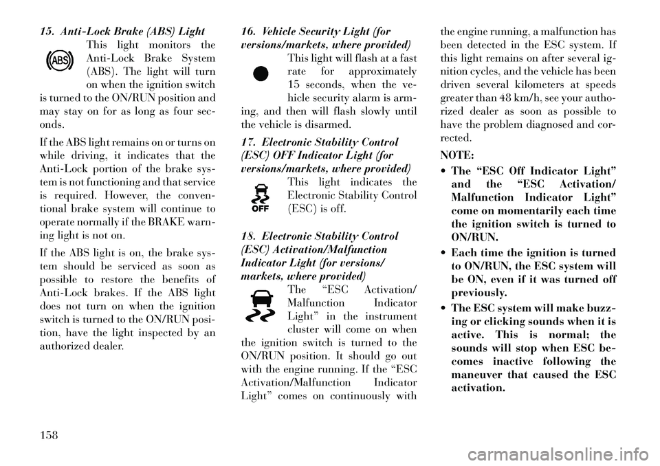
15. Anti-Lock Brake (ABS) LightThis light monitors the
Anti-Lock Brake System
(ABS). The light will turn
on when the ignition switch
is turned to the ON/RUN position and
may stay on for as long as four sec-
onds.
If the ABS light remains on or turns on
while driving, it indicates that the
Anti-Lock portion of the brake sys-
tem is not functioning and that service
is required. However, the conven-
tional brake system will continue to
operate normally if the BRAKE warn-
ing light is not on.
If the ABS light is on, the brake sys-
tem should be serviced as soon as
possible to restore the benefits of
Anti-Lock brakes. If the ABS light
does not turn on when the ignition
switch is turned to the ON/RUN posi-
tion, have the light inspected by an
authorized dealer. 16. Vehicle Security Light (for
versions/markets, where provided)
This light will flash at a fast
rate for approximately
15 seconds, when the ve-
hicle security alarm is arm-
ing, and then will flash slowly until
the vehicle is disarmed.
17. Electronic Stability Control
(ESC) OFF Indicator Light (for
versions/markets, where provided) This light indicates the
Electronic Stability Control
(ESC) is off.
18. Electronic Stability Control
(ESC) Activation/Malfunction
Indicator Light (for versions/
markets, where provided) The “ESC Activation/
Malfunction Indicator
Light” in the instrument
cluster will come on when
the ignition switch is turned to the
ON/RUN position. It should go out
with the engine running. If the “ESC
Activation/Malfunction Indicator
Light” comes on continuously with the engine running, a malfunction has
been detected in the ESC system. If
this light remains on after several ig-
nition cycles, and the vehicle has been
driven several kilometers at speeds
greater than 48 km/h, see your autho-
rized dealer as soon as possible to
have the problem diagnosed and cor-
rected.
NOTE:
The “ESC Off Indicator Light”
and the “ESC Activation/
Malfunction Indicator Light”
come on momentarily each time
the ignition switch is turned to
ON/RUN.
Each time the ignition is turned to ON/RUN, the ESC system will
be ON, even if it was turned off
previously.
The ESC system will make buzz- ing or clicking sounds when it is
active. This is normal; the
sounds will stop when ESC be-
comes inactive following the
maneuver that caused the ESC
activation.158