start stop button Lancia Thema 2012 Owner handbook (in English)
[x] Cancel search | Manufacturer: LANCIA, Model Year: 2012, Model line: Thema, Model: Lancia Thema 2012Pages: 316, PDF Size: 3.85 MB
Page 18 of 316

A WORD ABOUT YOUR
KEYS
Your vehicle uses a keyless ignition
system. This system consists of a Key
Fob with Remote Keyless Entry
(RKE) transmitter and a Keyless Ig-
nition Node (KIN).
Keyless Enter-N-Go Feature
This vehicle is equipped with the Key-
less Enter-N-Go feature, refer to
“Starting Procedure” in “Starting
And Operating” for further informa-
tion.
KEYLESS IGNITION NODE
(KIN)
This feature allows the driver to oper-
ate the ignition switch with the push
of a button, as long as the Remote
Keyless Entry (RKE) transmitter is in
the passenger compartment.
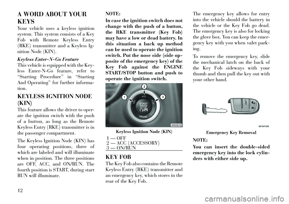
The Keyless Ignition Node (KIN) has
four operating positions, three of
which are labeled and will illuminate
when in position. The three positions
are OFF, ACC, and ON/RUN. The
fourth position is START, during start
RUN will illuminate.NOTE:
In case the ignition switch does not
change with the push of a button,
the RKE transmitter (Key Fob)
may have a low or dead battery. In
this situation a back up method
can be used to operate the ignition
switch. Put the nose side (side op-
posite of the emergency key) of the
Key Fob against the ENGINE
START/STOP button and push to
operate the ignition switch.
KEY FOB
The Key Fob also contains the Remote
Keyless Entry (RKE) transmitter and
an emergency key, which stores in the
rear of the Key Fob.The emergency key allows for entry
into the vehicle should the battery in
the vehicle or the Key Fob go dead.
The emergency key is also for locking
the glove box. You can keep the emer-
gency key with you when valet park-
ing.
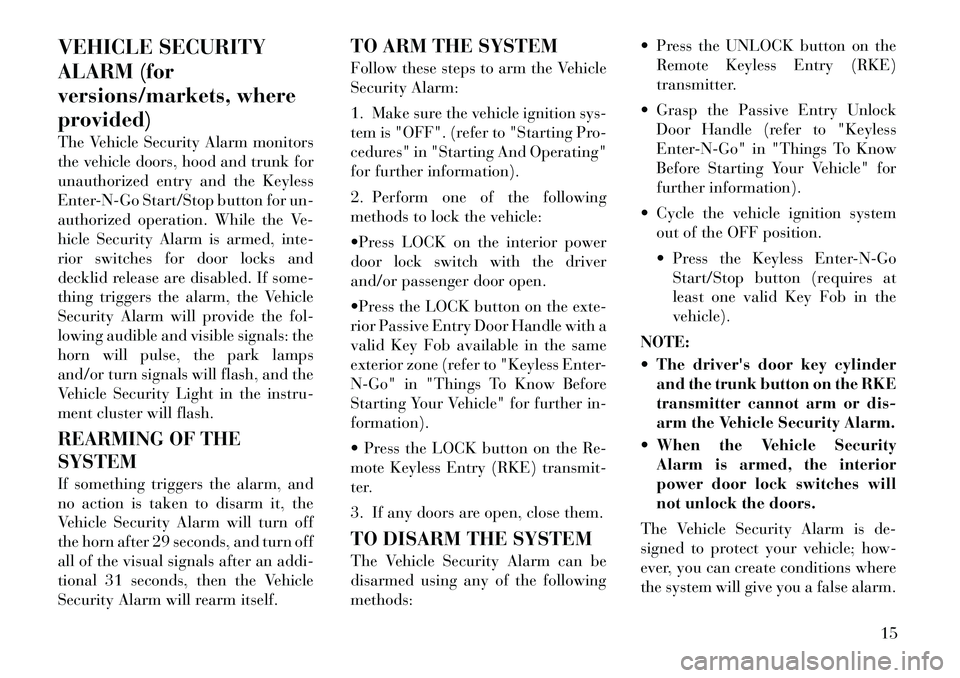
To remove the emergency key, slide
the mechanical latch on the back of
the Key Fob sideways with your
thumb and then pull the key out with
your other hand.
NOTE:
You can insert the double-sided
emergency key into the lock cylin-
ders with either side up.
Keyless Ignition Node (KIN)
1 — OFF
2 — ACC (ACCESSORY)
3 — ON/RUN
Emergency Key Removal
12
Page 21 of 316

VEHICLE SECURITY
ALARM (for
versions/markets, where
provided)
The Vehicle Security Alarm monitors
the vehicle doors, hood and trunk for
unauthorized entry and the Keyless
Enter-N-Go Start/Stop button for un-
authorized operation. While the Ve-
hicle Security Alarm is armed, inte-
rior switches for door locks and
decklid release are disabled. If some-
thing triggers the alarm, the Vehicle
Security Alarm will provide the fol-
lowing audible and visible signals: the
horn will pulse, the park lamps
and/or turn signals will flash, and the
Vehicle Security Light in the instru-
ment cluster will flash.
REARMING OF THE
SYSTEM
If something triggers the alarm, and
no action is taken to disarm it, the
Vehicle Security Alarm will turn off
the horn after 29 seconds, and turn off
all of the visual signals after an addi-
tional 31 seconds, then the Vehicle
Security Alarm will rearm itself.TO ARM THE SYSTEM
Follow these steps to arm the Vehicle
Security Alarm:
1. Make sure the vehicle ignition sys-
tem is "OFF". (refer to "Starting Pro-
cedures" in "Starting And Operating"
for further information).
2. Perform one of the following
methods to lock the vehicle:
Press LOCK on the interior power
door lock switch with the driver
and/or passenger door open.
Press the LOCK button on the exte-
rior Passive Entry Door Handle with a
valid Key Fob available in the same
exterior zone (refer to "Keyless Enter-
N-Go" in "Things To Know Before
Starting Your Vehicle" for further in-
formation).
Press the LOCK button on the Re-
mote Keyless Entry (RKE) transmit-
ter.
3. If any doors are open, close them.
TO DISARM THE SYSTEM
The Vehicle Security Alarm can be
disarmed using any of the following
methods: Press the UNLOCK button on the
Remote Keyless Entry (RKE)
transmitter.
Grasp the Passive Entry Unlock Door Handle (refer to "Keyless
Enter-N-Go" in "Things To Know
Before Starting Your Vehicle" for
further information).
Cycle the vehicle ignition system out of the OFF position.
Press the Keyless Enter-N-GoStart/Stop button (requires at
least one valid Key Fob in the
vehicle).
NOTE:
The driver's door key cylinder and the trunk button on the RKE
transmitter cannot arm or dis-
arm the Vehicle Security Alarm.
When the Vehicle Security Alarm is armed, the interior
power door lock switches will
not unlock the doors.
The Vehicle Security Alarm is de-
signed to protect your vehicle; how-
ever, you can create conditions where
the system will give you a false alarm.
15
Page 45 of 316

Driver Side Knee Air Bag gas is vented
through small vent holes in the side of
the air bag.
Supplemental Seat-Mounted Side
Air Bag (SAB) Inflator Units
The Supplemental Seat-Mounted
Side Air Bags (SAB) are designed to
activate only in certain side collisions.
The ORC determines if a side collision
requires the side air bags to inflate,
based on several factors, including the
severity and type of collision.
Based on several factors, including
the severity and type of collision, the
side air bag inflator on the crash side
of the vehicle may be triggered, re-
leasing a quantity of non-toxic gas.
The inflating SAB exits through the
seat seam into the space between the
occupant and the door. The SAB fully
inflate in about 10 milliseconds. The
side air bag moves at a very high
speed and with such a high force that
it could injure you if you are not
seated properly, or if items are posi-
tioned in the area where the side air
bag inflates. This especially applies to
children.Supplemental Side Air Bag
Inflatable Curtain (SABIC)
Inflator Units
During collisions where the impact is
confined to a particular area of the
side of the vehicle, the ORC may de-
ploy the SABIC air bags, depending
on the severity and type of collision. In
these events, the ORC will deploy the
SABIC only on the impact side of the
vehicle.
A quantity of non-toxic gas is gener-
ated to inflate the side curtain air bag.
The inflating side curtain air bag
pushes the outside edge of the head-
liner out of the way and covers the
window. The air bag inflates in about
30 milliseconds (about one-quarter of
the time that it takes to blink your
eyes) with enough force to injure you
if you are not belted and seated prop-
erly, or if items are positioned in the
area where the side curtain air bag
inflates. This especially applies to
children. The side curtain air bag is
only about 9 cm thick when it is in-
flated.
Because air bag sensors estimate de-
celeration over time, vehicle speedand damage are not good indicators of
whether or not an air bag should have
deployed.
Front And Side Impact Sensors
In front and side impacts, impact sen-
sors can aid the ORC in determining
appropriate response to impact events.Enhanced Accident Response
System
In the event of an impact causing air
bag deployment, if the communica-
tion network remains intact, and the
power remains intact, depending on
the nature of the event the ORC will
determine whether to have the En-
hanced Accident Response System
perform the following functions:
Cut off fuel to the engine.
Flash hazard lights as long as the
battery has power or until the igni-
tion key is turned off.
Turn on the interior lights, which remain on as long as the battery has
power, until the ignition key is re-
moved or the ignition switch is
changed to OFF using the Keyless
Go Start/Stop button.
Unlock the doors automatically.
39
Page 158 of 316

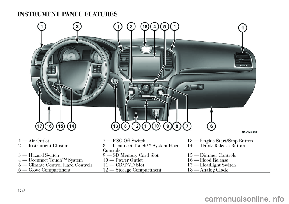
INSTRUMENT PANEL FEATURES1 — Air Outlet7 — ESC Off Switch13 — Engine Start/Stop Button
2 — Instrument Cluster 8 — Uconnect Touch™ System Hard
Controls 14 — Trunk Release Button
3 — Hazard Switch 9 — SD Memory Card Slot15 — Dimmer Controls
4 — Uconnect Touch™ System 10 — Power Outlet 16 — Hood Release
5 — Climate Control Hard Controls 11 — CD/DVD Slot 17 — Headlight Switch
6 — Glove Compartment 12 — Storage Compartment18 — Analog Clock
152
Page 197 of 316

STARTING
PROCEDURES
Before starting your vehicle, adjust
your seat, adjust the inside and out-
side mirrors, fasten your seat belt, and
if present, instruct all other occupants
to buckle their seat belts.WARNING!
When leaving the vehicle, alwaysremove the key fob and lock your
vehicle.
Never leave children alone in a
vehicle, or with access to an un-
locked vehicle. Allowing children
to be in a vehicle unattended is
dangerous for a number of rea-
sons. A child or others could be
seriously or fatally injured. Chil-
dren should be warned not to
touch the parking brake, brake
pedal or the shift lever.
Do not leave the key fob in or near
the vehicle, and do not leave Key-
less Enter-N-Go in the ACC or
ON/RUN mode. A child could op-
erate power windows, other con-
trols, or move the vehicle. AUTOMATIC
TRANSMISSION
The shift lever must be in the NEU-
TRAL or PARK position before you
can start the engine. Apply the brakes
before shifting into any driving gear.
CAUTION!
Damage to the transmission may oc-
cur if the following precautions are
not observed:
Shift into PARK only after the ve-
hicle has come to a complete stop.
Shift into or out of REVERSE
only after the vehicle has come to
a complete stop and the engine is
at idle speed.
Do not shift between PARK, RE-
VERSE, NEUTRAL, or DRIVE
when the engine is above idle
speed.
Before shifting into any gear,
make sure your foot is firmly
pressing the brake pedal. KEYLESS ENTER-N-GO
This feature allows
the driver to oper-
ate the ignition
switch with the
push of a button,
as long as the Re-
mote Keyless En-
try (RKE) transmitter is in the pas-
senger compartment.
NORMAL STARTING —
GASOLINE ENGINE
Using The ENGINE START/STOP
Button
NOTE:
Normal starting of either a cold or
a warm engine is obtained without
pumping or pressing the accelera-
tor pedal.
To start the engine, the transmission
must be in PARK or NEUTRAL. Press
and hold the brake pedal while press-
ing the ENGINE START/STOP but-
ton once. The system takes over and
attempts to start the vehicle. If the
vehicle fails to start, the starter will
disengage automatically after 10 sec-
191
Page 198 of 316

onds. If you wish to stop the cranking
of the engine prior to the engine start-
ing, press the button again.
To Turn Off The Engine Using
ENGINE START/STOP Button
1. Place the shift lever in PARK, then
press and release the ENGINE
START/STOP button.
2. The ignition switch will return to
the OFF position.
3. If the shift lever is not in PARK, the
ENGINE START/STOP button must
be held for two seconds and vehicle
speed must be above 8 km/h before
the engine will shut off. The ignition
switch position will remain in the
ACC position until the shift lever is in
PARK and the button is pressed twice
to the OFF position. If the shift lever is
not in PARK and the ENGINE
START/STOP button is pressed once,
the EVIC (for versions/markets,
where provided) will display a “Ve-
hicle Not In Park” message and the
engine will remain running. Never
leave a vehicle out of the PARK posi-
tion, or it could roll.NOTE:
If the ignition switch is left in the
ACC or RUN (engine not running)
position and the transmission is in
PARK, the system will automati-
cally time out after 30 minutes of
inactivity and the ignition will
switch to the OFF position.
ENGINE START/STOP Button
Functions – With Driver’s Foot
OFF The Brake Pedal (In PARK
Or NEUTRAL Position)
The Keyless Enter-N-Go feature oper-
ates similar to an ignition switch. It
has four positions, OFF, ACC, RUN
and START. To change the ignition
switch positions without starting the
vehicle and use the accessories follow
these steps.
Starting with the ignition switch in
the OFF position:
Press the ENGINE START/STOP button once to change the ignition
switch to the ACC position (ACC
will illuminate),
Press the ENGINE START/STOP button a second time to change the ignition switch to the RUN position
(RUN will illuminate),
Press the ENGINE START/STOP button a third time to return the
ignition switch to the OFF position
(OFF will illuminate).
EXTREME COLD
WEATHER (BELOW �29°C)
To ensure reliable starting at these
temperatures, use of an externally
powered electric engine block heater
is recommended.
IF ENGINE FAILS TO
START
WARNING!
Never pour fuel or other flam- mable liquids into the throttle
body air inlet opening in an at-
tempt to start the vehicle. This
could result in a flash fire causing
serious personal injury.
(Continued)
192
Page 199 of 316

WARNING!(Continued)
Do not attempt to push or tow
your vehicle to get it started. Ve-
hicles equipped with an automatic
transmission cannot be started
this way. Unburned fuel could en-
ter the catalytic converter and
once the engine has started, ignite
and damage the converter and ve-
hicle. If the vehicle has a dis-
charged battery, booster cables
may be used to obtain a start from
a booster battery or the battery in
another vehicle. This type of start
can be dangerous if done improp-
erly. Refer to “Jump Starting” in
“What To Do In Emergencies” for
further information.
Clearing A Flooded Engine (Using
ENGINE START/STOP Button)
If the engine fails to start after you
have followed the “Normal Starting”
or “Extreme Cold Weather" proce-
dures, it may be flooded. To clear any
excess fuel, press and hold the brake
pedal, push the accelerator pedal all
the way to the floor and hold it, then
press and release the ENGINE START/STOP button once. The
starter motor will engage automati-
cally, run for 10 seconds, and then
disengage. Once this occurs, release
the accelerator pedal and the brake
pedal, wait 10 to 15 seconds, then
repeat the “Normal Starting” proce-
dure.
After Starting
The idle speed is controlled automati-
cally and it will decrease as the engine
warms up.
NORMAL STARTING –
DIESEL ENGINE
Observe the following when the en-
gine is operating.
All message center lights are off.
Malfunction Indicator Light (MIL)
is off.
Low Oil Pressure Light is off.
Cold Weather Precautions
If the outside temperature is very low,
the diesel fuel thickens due to the
formation of parrafin clots and could
clog the diesel filter. In order to avoid
these problems, different types of die-
sel fuel are distributed according to the season: summer type, winter type
and arctic type (cold, mountainous
areas).
If refuelling with diesel fuel whose
specifications are not suitable for the
outside temperature, it is advisable to
mix TUTELA DIESEL ART additive
in the proportions shown on the con-
tainer with the fuel. Pour the additive
into the tank before the fuel.
When using or parking the vehicle for
a long time in the mountains or cold
areas, it is advisable to refuel using
locally available diesel. In this case, it
is also advisable to keep the tank over
50% full.
Battery Blanket Usage
A battery loses 60% of its cranking
power as the battery temperature de-
creases to 18°C. For the same de-
crease in temperature, the engine re-
quires twice as much power to crank
at the same RPM. The use of battery
blankets will greatly increase starting
capability at low temperatures.
193
Page 200 of 316

Engine Starting ProcedureWARNING!
Never pour fuel or other flammable
liquid into the air inlet opening in an
attempt to start the vehicle. This
could result in a flash fire causing
serious personal injury.
1. The shift lever must be in the
NEUTRAL or PARK position before
you can start the engine.
2. With your foot on the brake pedal,
press the ENGINE START/STOP
button.
3. Watch the “Wait To Start Light” in
the instrument cluster. Refer to “In-
strument Cluster” in “Understanding
Your Instrument Panel” for further
information. It may glow for up to
three seconds, depending on engine
temperature.
4. When the “Wait To Start Light”
goes out, the engine will automati-
cally start.
5. After the engine starts, allow it to
idle for approximately 30 seconds be-
fore driving. This allows oil to circu-
late and lubricate the turbocharger. Avoid prolonged idling in ambient
temperatures below 18°C. Long pe-
riods of idling may be harmful to your
engine because combustion chamber
temperatures can drop so low that the
fuel may not burn completely. Incom-
plete combustion allows carbon and
varnish to form on piston rings and
injector nozzles. Also, the unburned
fuel can enter the crankcase, diluting
the oil and causing rapid wear to the
engine.
Engine Warm Up
Avoid full throttle operation when the
engine is cold. When starting a cold
engine, bring the engine up to operat-
ing speed slowly to allow the oil pres-
sure to stabilize as the engine warms
up.
NOTE:
High-speed, no-load running of a
cold engine can result in excessive
white smoke and poor engine per-
formance. No-load engine speeds
should be kept under 1,200 RPM
during the warm-up period, espe-
cially in cold ambient temperature
conditions.
If temperatures are below 0°C, operate
the engine at moderate speeds for five
minutes before full loads are applied.Engine Idling – In Cold WeatherAvoid prolonged idling in ambient tem-
peratures below 18°C. Long periods of
idling may be harmful to your engine
because combustion chamber tempera-
tures can drop so low that the fuel may
not burn completely. Incomplete com-
bustion allows carbon and varnish to
form on piston rings and injector
nozzles. Also, the unburned fuel can
enter the crankcase, diluting the oil and
causing rapid wear to the engine.Stopping The Engine
Before turning off your turbo diesel
engine, always allow the engine to
return to normal idle speed and run
for several seconds. This assures
proper lubrication of the turbo-
charger. This is particularly necessary
after any period of hard driving.
Idle the engine a few minutes before
routine shutdown. After full load op-
eration, idle the engine three to five
minutes before shutting it down. This
idle period will allow the lubricating
194
Page 202 of 316

in PARK whenever the ignition switch
is in the OFF position.
BRAKE/TRANSMISSION
SHIFT INTERLOCK
SYSTEM
This vehicle is equipped with a Brake
Transmission Shift Interlock (BTSI)
that holds the shift lever in the PARK
position unless the brakes are applied.
To move the shift lever out of the
PARK position, the ignition switch
must be turned to the ON/RUN or
START position (engine running or
not) and the brake pedal must be
pressed.
EIGHT-SPEED AUTOMATIC
TRANSMISSION – 3.6L
ENGINE
The transmission gear display
(PRND) (located in the instrument
panel cluster) indicates the transmis-
sion gear range. Transmission gear
state is also indicated in the display in
the shift knob. The shift lever is
spring-loaded and returns to a home
position when it is released. To select a
gear range, press the lock button on
the shift lever and move the lever rear-ward or forward. You must also press
the brake pedal to shift the transmis-
sion out of the PARK position (refer to
“Brake/Transmission Shift Interlock
System” in this section). To shift past
multiple gear ranges at once (such as
PARK to DRIVE), move the lever past
the first (or second) detent. Select the
DRIVE range for normal driving.
The electronically-controlled trans-
mission provides a precise shift sched-
ule. The transmission electronics are
self-calibrating; therefore, the first
few shifts on a new vehicle may be
somewhat abrupt. This is a normal
condition, and precision shifts will de-
velop within a few hundred kilome-
ters.
Shifting from DRIVE to PARK or RE-
VERSE should be done only after the
accelerator pedal is released and the
vehicle is stopped. Be sure to keep
your foot on the brake pedal when
moving the shift lever between these
gears.
The shift lever has PARK, REVERSE,
NEUTRAL, DRIVE, and LOW shift
positions. Using the LOW position
manually downshifts the transmission
to a lower gear based on vehicle speed.
GEAR RANGES
DO NOT race the engine when shift-
ing from PARK or NEUTRAL into
another gear range.
PARK
This range supplements the parking
brake by locking the transmission.
The engine can be started in this
range. Never attempt to use PARK
while the vehicle is in motion. Apply
the parking brake when leaving the
vehicle in this range.
When parking on a level surface, you
may place the shift lever in the PARK
position first, and then apply the
parking brake.
When parking on a hill, apply the
parking brake before placing the shift
lever in PARK. As an added precau-
tion, turn the front wheels toward the
curb on a downhill grade and away
from the curb on an uphill grade.
196
Page 249 of 316

WARNING!(Continued)
Take care not to allow the con-
tents of TIREFIT to come in con-
tact with hair, eyes, or clothing.
TIREFIT is harmful if inhaled,
swallowed, or absorbed through
the skin. It causes skin, eye, and
respiratory irritation. Flush im-
mediately with plenty of water if
there is any contact with eyes or
skin. Change clothing as soon as
possible, if there is any contact
with clothing.
TIREFIT Sealant solution con-
tains latex. In case of an allergic
reaction or rash, consult a physi-
cian immediately. Keep TIREFIT
out of reach of children. If swal-
lowed, rinse mouth immediately
with plenty of water and drink
plenty of water. Do not induce
vomiting! Consult a physician im-
mediately. SEALING A TIRE WITH
TIREFIT
(A) Whenever You Stop To Use
TIREFIT:
1. Pull over to a safe location and
turn on the vehicle’s Hazard Warning
flashers.
2. Verify that the valve stem (on the
wheel with the deflated tire) is in a
position that is near to the ground.
This will allow the TIREFIT Hoses
(6) and (7) to reach the valve stem
and keep the TIREFIT kit flat on the
ground. This will provide the best po-
sitioning of the kit when injecting the
sealant into the deflated tire and run-
ning the air pump. Move the vehicle as
necessary to place the valve stem in
this position before proceeding.
3. Place the transmission in PARK
(auto transmission) or in Gear
(manual transmission) and turn Off
the ignition.
4. Set the parking brake.
(B) Setting Up To Use TIREFIT:
1. Turn the Mode Select Knob (5) to
the Sealant Mode position. 2. Uncoil the Sealant Hose (6) and
then remove the cap from the fitting
at the end of the hose.
3. Place the TIREFIT kit flat on the
ground next to the deflated tire.
4. Remove the cap from the valve
stem and then screw the fitting at the
end of the Sealant Hose (6) onto the
valve stem.
5. Uncoil the Power Plug (8) and in-
sert the plug into the vehicle’s 12 Volt
power outlet.
NOTE:
Do not remove foreign objects (e.g.,
screws or nails) from the tire.
(C) Injecting TIREFIT Sealant
Into The Deflated Tire:
Always start the engine before
turning ON the TIREFIT kit.
NOTE:
Manual transmission vehicles
must have the parking brake en-
gaged and the shift lever in NEU-
TRAL.
After pressing the Power Button (4), the sealant (white fluid) will
243