battery Lancia Thema 2013 Owner handbook (in English)
[x] Cancel search | Manufacturer: LANCIA, Model Year: 2013, Model line: Thema, Model: Lancia Thema 2013Pages: 336, PDF Size: 3.87 MB
Page 92 of 336
Barge In — Overriding Prompts
The
button can be used when
you wish to skip part of a prompt and
issue your voice command immedi-
ately. For example, if a prompt is ask-
ing “There are 2 numbers with the
name John. Say the full name” you
could press the
button and say,
“John Smith” to select that option
without having to listen to the rest of
the voice prompt.
Voice Response Length
It is possible for you to choose between
Brief and Detailed Voice Response
Length.Touch the “More” soft-key (where
available), then touch the “Settings”
soft-key,Touch the “Display” soft-key, then
scroll down to Voice Response
Length, Select either “Brief” or “Detailed”
by touching the box next to the
selection. A check-mark will ap-
pear to show your selection. Phone And Network Status
Indicators
Uconnect™ Phone will provide noti-
fication to inform you of your phone
and network status when you are
attempting to make a phone call using
Uconnect™ Phone. The status is
given for network signal strength and
phone battery strength.
Dialing Using The Mobile Phone
Keypad
WARNING!Your new vehicle has many features
for the comfort and convenience of
you and your passengers. Some of
these should not be used when driv-
ing because they take your eyes
from the road or your attention
from driving. Never dial using the
mobile phone keypad while driving.You can dial a phone number with your
mobile phone keypad and still use the
Uconnect™ Phone (while dialing via
the mobile phone keypad, the user
must exercise caution and take precau-
tionary safety measures). By dialing a number with your paired Bluetooth®
mobile phone, the audio will be played
through your vehicle's audio system.
The Uconnect™ Phone will work the
same as if you dial the number using
voice a command.
NOTE: Certain brands of mobile
phones do not send the dial ring to
the Uconnect™ Phone to play it on
the vehicle audio system, so you
will not hear it. Under this situa-
tion, after successfully dialing a
number the user may feel that the
call did not go through even
though the call is in progress. Once
your call is answered, you will
hear the audio.
Mute/Un-Mute (Mute ON/OFF)When you mute the Uconnect™
Phone, you will still be able to hear the
conversation coming from the other
party, but the other party will not be
able to hear you. In order to mute the
Uconnect™ Phone simply touch the
Mute button on the Phone main screen.
86
Page 119 of 336
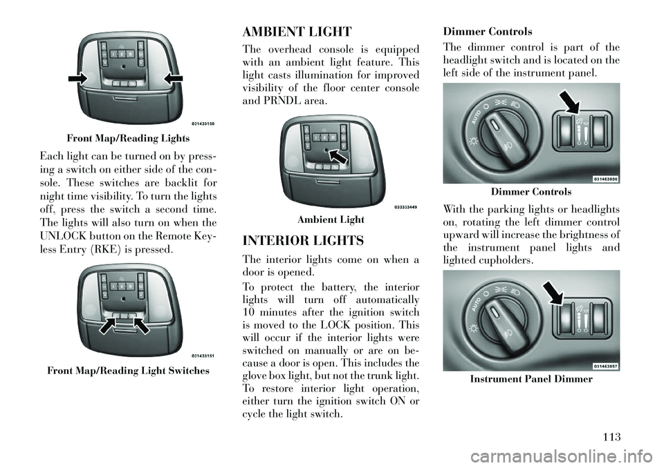
Each light can be turned on by press-
ing a switch on either side of the con-
sole. These switches are backlit for
night time visibility. To turn the lights
off, press the switch a second time.
The lights will also turn on when the
UNLOCK button on the Remote Key-
less Entry (RKE) is pressed.AMBIENT LIGHT
The overhead console is equipped
with an ambient light feature. This
light casts illumination for improved
visibility of the floor center console
and PRNDL area.
INTERIOR LIGHTS
The interior lights come on when a
door is opened.
To protect the battery, the interior
lights will turn off automatically
10 minutes after the ignition switch
is moved to the LOCK position. This
will occur if the interior lights were
switched on manually or are on be-
cause a door is open. This includes the
glove box light, but not the trunk light.
To restore interior light operation,
either turn the ignition switch ON or
cycle the light switch.
Dimmer Controls
The dimmer control is part of the
headlight switch and is located on the
left side of the instrument panel.
With the parking lights or headlights
on, rotating the left dimmer control
upward will increase the brightness of
the instrument panel lights and
lighted cupholders.
Front Map/Reading Lights
Front Map/Reading Light Switches
Ambient Light
Dimmer Controls
Instrument Panel Dimmer
113
Page 152 of 336

The center console outlet is powered
directly from the battery (power
available at all times). Items plugged
into this outlet may discharge the
battery and/or prevent the engine
from starting.
There is also a 12 volt power outlet
located on the back of the center con-
sole for rear passengers. This power
outlet has power available only when
the ignition is placed in the ACC or
RUN position.
WARNING!
To avoid serious injury or death:
Only devices designed for use inthis type of outlet should be in-
serted into any 12 Volt outlet.
Do not touch with wet hands.
Close the lid when not in use and while driving the vehicle.
If this outlet is mishandled, it may cause an electric shock and fail-
ure.
CAUTION!
Many accessories that can beplugged in draw power from the
vehicle's battery even when not in
use (i.e., cellular phones, etc.).
Eventually, if plugged in long
enough, the vehicle's battery will
discharge sufficiently to degrade
battery life and/or prevent the
engine from starting.
Accessories that draw higher
power (i.e., coolers, vacuum
cleaners, lights, etc.) will degrade
the battery even more quickly.
Only use these intermittently and
with greater caution.
After the use of high power draw accessories or long periods of the
vehicle not being started (with
accessories still plugged in), the
vehicle must be driven a suffi-
cient length of time to allow the
alternator to recharge the vehi-
cle's battery.
(Continued)
Center Console Power Outlet
Rear Center Console Power Outlet
Power Outlet Fuse Locations
1 — #12 Fuse 20 A Yellow Cigar
Lighter Instrument Panel And Power
Outlet Console Rear
2 — #38 Fuse 20 A Yellow Power
Outlet Inside Arm Rest
146
Page 202 of 336
NOTE:
If the ignition switch is
left in the ACC or RUN (engine not
running) position and the trans-
mission is in PARK, the system
will automatically time out after
30 minutes of inactivity and the
ignition will switch to the OFF
position.
ENGINE START/STOP Button
Functions – With Driver’s Foot
OFF The Brake Pedal (In PARK
Or NEUTRAL Position)
The Keyless Enter-N-Go feature oper-
ates similar to an ignition switch. It
has four positions, OFF, ACC, RUN
and START. To change the ignition
switch positions without starting the
vehicle and use the accessories follow
these steps.
Starting with the ignition switch in the OFF position:
Press the ENGINE START/STOP button once to change the ignition
switch to the ACC position (ACC
will illuminate), Press the ENGINE START/STOP
button a second time to change the
ignition switch to the RUN position
(RUN will illuminate),
Press the ENGINE START/STOP button a third time to return the
ignition switch to the OFF position
(OFF will illuminate).
EXTREME COLD
WEATHER (BELOW 29°C)
To ensure reliable starting at these
temperatures, use of an externally
powered electric engine block heater
is recommended.
IF ENGINE FAILS TO
START
WARNING!
Never pour fuel or other flam- mable liquids into the throttle
body air inlet opening in an at-
tempt to start the vehicle. This
could result in a flash fire causing
serious personal injury.
(Continued)
WARNING!(Continued)
Do not attempt to push or tow your vehicle to get it started. Ve-
hicles equipped with an auto-
matic transmission cannot be
started this way. Unburned fuel
could enter the catalytic con-
verter and once the engine has
started, ignite and damage the
converter and vehicle.
If the vehicle has a discharged battery, booster cables may be
used to obtain a start from a
booster battery or the battery in
another vehicle. This type of start
can be dangerous if done improp-
erly. Refer to “Jump Starting” in
“What To Do In Emergencies” for
further information.
196
Page 203 of 336
Clearing A Flooded Engine (Using
ENGINE START/STOP Button)
If the engine fails to start after you
have followed the “Normal Starting”
or “Extreme Cold Weather" proce-
dures, it may be flooded. To clear any
excess fuel:
1. Press and hold the brake pedal.
2. Press the accelerator pedal all the
way to the floor and hold it.
3. Press and release the ENGINE
START/STOP button once.
The starter motor will engage auto-
matically, run for 10 seconds, and
then disengage. Once this occurs, re-
lease the accelerator pedal and the
brake pedal, wait 10 to 15 seconds,
then repeat the “Normal Starting”
procedure.
After Starting
The idle speed is controlled automati-
cally and it will decrease as the engine
warms up.NORMAL STARTING –
DIESEL ENGINE
Observe the following when the en-
gine is operating.
All message center lights are off.
Malfunction Indicator Light (MIL)
is off.
Low Oil Pressure Light is off.
Cold Weather Precautions
If the outside temperature is very low,
the diesel fuel thickens due to the
formation of parrafin clots and could
clog the diesel filter. In order to avoid
these problems, different types of die-
sel fuel are distributed according to
the season: summer type, winter type
and arctic type (cold, mountainous
areas).
If refuelling with diesel fuel whose
specifications are not suitable for the
outside temperature, it is advisable to
mix TUTELA DIESEL ART additive
in the proportions shown on the con-
tainer with the fuel. Pour the additive
into the tank before the fuel. When using or parking the vehicle for
a long time in the mountains or cold
areas, it is advisable to refuel using
locally available diesel. In this case, it
is also advisable to keep the tank over
50% full.
Battery Blanket Usage
A battery loses 60% of its cranking
power as the battery temperature de-
creases to 18°C. For the same de-
crease in temperature, the engine re-
quires twice as much power to crank
at the same RPM. The use of battery
blankets will greatly increase starting
capability at low temperatures.
Engine Starting Procedure
WARNING!NEVER pour fuel or other flam-
mable liquid into the air inlet open-
ing in an attempt to start the vehicle.
This could result in a flash fire caus-
ing serious personal injury.1. The shift lever must be in the
NEUTRAL or PARK position before
you can start the engine.
197
Page 227 of 336

SYNCHRONIZING ESCIf the power supply is inter-
rupted (battery discon-
nected or discharged), the
“ESC Activation/Malfunc-
tion Indicator Light” may illuminate
with the engine running. If this should
occur, turn the steering wheel com-
pletely to the left and then to the right.
The “ESC Activation/Malfunction In-
dicator Light” should go out. How-
ever, if the light remains on, have the
ESC and BAS checked at your autho-
rized dealer as soon as possible. TIRE SAFETY
INFORMATION
Tire Markings
NOTE:
P (Passenger) - Metric tire sizing
is based on U.S. design stan-
dards. P-Metric tires have the
letter “P” molded into the side-
wall preceding the size designa-
tion. Example: P215/65R15 95H.
European-Metric tire sizing is
based on European design stan-
dards. Tires designed to this stan-
dard have the tire size molded into the sidewall beginning with
the section width. The letter "P" is
absent from this tire size designa-
tion. Example: 215/65R15 96H.
LT (Light Truck) - Metric tire siz-
ing is based on U.S. design stan-
dards. The size designation for
LT-Metric tires is the same as for
P-Metric tires except for the let-
ters “LT” that are molded into the
sidewall preceding the size desig-
nation. Example: LT235/85R16.Temporary spare tires are spares
designed for temporary emer-
gency use only. Temporary high
pressure compact spare tires have
the letter “T” or “S” molded into
the sidewall preceding the size
designation. Example: T145/
80D18 103M. High flotation tire sizing is
based on U.S. design standards
and it begins with the tire diam-
eter molded into the sidewall.
Example: 31x10.5 R15 LT.
1 — U.S. DOT Safety
Standards Code (TIN) 4 — Maximum Load
2 — Size Designation 5 — Maximum Pres-
sure
3 — Service Descrip-
tion 6 — Treadwear,
Traction and Tem-
perature Grades
221
Page 260 of 336
HAZARD WARNING
FLASHERS
The Hazard Warning flasher switch is
located in the center of the instrument
panel between the center air outlets.Press the switch to turn on the
Hazard Warning flashers.
When the switch is activated, all di-
rectional turn signals will flash on and
off to warn oncoming traffic of an
emergency. Press the switch a second
time to turn off the Hazard Warning
flashers.
This is an emergency warning system
and it should not be used when the
vehicle is in motion. Use it when your
vehicle is disabled and it is creating a
safety hazard for other motorists.
When you must leave the vehicle to
seek assistance, the Hazard Warning
flashers will continue to operate even
though the ignition is placed in the
OFF position.
NOTE: With extended use the
Hazard Warning flashers may
wear down your battery. IF YOUR ENGINE
OVERHEATS
In any of the following situations, you
can reduce the potential for overheat-
ing by taking the appropriate action.
On the highways — slow down.
In city traffic — while stopped,
place the transmission in NEU-
TRAL, but do not increase the en-
gine idle speed.
NOTE: There are steps that you
can take to slow down an impend-
ing overheat condition:
If your air conditioner (A/C) is on, turn it off. The A/C system
adds heat to the engine cooling
system and turning the A/C off
can help remove this heat.
You can also turn the tempera- ture control to maximum heat,
the mode control to floor and the
blower control to high. This al-
lows the heater core to act as a
supplement to the radiator and
aids in removing heat from the
engine cooling system.
CAUTION!
Driving with a hot cooling system
could damage your vehicle. If the
temperature gauge reads “H,” pull
over and stop the vehicle. Idle the
vehicle with the air conditioner
turned off until the pointer drops
back into the normal range. If the
pointer remains on the “H,” turn
the engine off immediately and call
for service.WARNING!You or others can be badly burned
by hot engine coolant (antifreeze) or
steam from your radiator. If you see
or hear steam coming from under
the hood, do not open the hood until
the radiator has had time to cool.
Never try to open a cooling system
pressure cap when the radiator or
coolant bottle is hot.
254
Page 266 of 336

NOTE: If the tire becomes over-
inflated, press the Deflation But-
ton to reduce the tire pressure to
the recommended inflation pres-
sure before continuing.
2. Disconnect the TIREFIT kit from
the valve stem, reinstall the cap on the
valve stem and unplug from 12 Volt
outlet.
3. Place the TIREFIT kit in its proper
storage area in the vehicle.
4. Have the tire inspected and re-
paired or replaced at the earliest op-
portunity at an authorized dealer or
tire service center.
5. Replace the Sealant Bottle (1) and
Sealant Hose (6) assembly at your
authorized dealer as soon as possible.
Refer to “(F) Sealant Bottle and Hose
Replacement.”
NOTE: When having the tire ser-
viced, advise the authorized dealer
or service center that the tire has
been sealed using the TIREFIT
service kit.(F) Sealant Bottle And Hose
Replacement:
1. Uncoil the Sealant Hose (6) (clear
in color).
2. Locate the round Sealant Bottle
release button in the recessed area
under the sealant bottle.
3. Press the Sealant Bottle release
button. The Sealant Bottle (1) will
pop up. Remove the bottle and dis-
pose of it accordingly.
4. Clean any remaining sealant from
the TIREFIT housing.
5. Position the new Sealant Bottle (1)
in the housing so that the Sealant
Hose (6) aligns with the hose slot in
the front of the housing. Press the
bottle into the housing. An audible
click will be heard indicating the
bottle is locked into place.
6. Verify that the cap is installed on
the fitting at the end of the Sealant
Hose (6) and return the hose to its
storage area (located on the bottom of
the air pump).
7. Return the TIREFIT kit to its stor-
age location in the vehicle.JUMP-STARTING
PROCEDURES
If your vehicle has a discharged bat-
tery it can be jump-started using a set
of jumper cables and a battery in an-
other vehicle or by using a portable
battery booster pack. Jump-starting
can be dangerous if done improperly
so please follow the procedures in this
section carefully.
NOTE: When using a portable
battery booster pack follow the
manufacturer’s operating instruc-
tions and precautions.
CAUTION!
Do not use a portable battery
booster pack or any other booster
source with a system voltage
greater than 12 Volts or damage to
the battery, starter motor, alterna-
tor or electrical system may occur.WARNING!
Do not attempt jump-starting if the
battery is frozen. It could rupture or
explode and cause personal injury.
260
Page 267 of 336

PREPARATIONS FOR
JUMP-START
The battery is stored under an access
cover in the trunk. Remote battery
posts are located on the right side of
the engine compartment for jump-
starting.
NOTE: The remote battery posts
are viewed by standing on the right
side of the vehicle looking over the
fender.
WARNING!
Take care to avoid the radiatorcooling fan whenever the hood is
raised. It can start anytime the
ignition switch is ON. You can be
injured by moving fan blades.
Remove any metal jewelry such
as watch bands or bracelets that
might make an inadvertent elec-
trical contact. You could be seri-
ously injured.
Batteries contain sulfuric acid that can burn your skin or eyes
and generate hydrogen gas which
is flammable and explosive. Keep
open flames or sparks away from
the battery.
1. Set the parking brake, shift the
automatic transmission into PARK
and turn the ignition to LOCK.
2. Turn off the heater, radio, and all
unnecessary electrical accessories.
3. If using another vehicle to jump-
start the battery, park the vehicle
within the jumper cables reach, set
the parking brake and make sure the
ignition is OFF.
WARNING!
Do not allow vehicles to touch each
other as this could establish a
ground connection and personal
injury could result.
JUMP-STARTING
PROCEDUREWARNING!
Failure to follow this procedure
could result in personal injury or
property damage due to battery
explosion.CAUTION!
Failure to follow these procedures
could result in damage to the
charging system of the booster ve-
hicle or the discharged vehicle.
1. Connect the positive (+)end of the
jumper cable to the remote posi-
tive (+)post of the discharged vehicle.
2. Connect the opposite end of the
positive (+)jumper cable to the posi-
tive (+)post of the booster battery.
Remote Battery Post Locations
1 — Remote Positive (+)Post
2 — Remote Negative (-)Post
261
Page 268 of 336

3. Connect the negative end(-)of the
jumper cable to the negative (-)post
of the booster battery.
4. Connect the opposite end of the
negative (-)jumper cable to the re-
mote negative (-)post of the vehicle
with the discharged battery.WARNING!
Do not connect the cable to the
negative post (-)of the discharged
battery. The resulting electrical
spark could cause the battery to
explode and could result in per-
sonal injury.
5. Start the engine in the vehicle that
has the booster battery, let the engine
idle a few minutes, and then start the
engine in the vehicle with the dis-
charged battery.
Once the engine is started, remove the
jumper cables in the reverse sequence:
6. Disconnect the negative (-)jumper
cable from the remote negative (-)
post of the vehicle with the discharged
battery. 7. Disconnect the negative end
(-)of
the jumper cable from the negative (-)
post of the booster battery.
8. Disconnect the opposite end of the
positive (+)jumper cable from the
positive (+)post of the booster bat-
tery.
9. Disconnect the positive (+)end of
the jumper cable from the remote
positive (+)post of the discharged
vehicle.
If frequent jump-starting is required
to start your vehicle you should have
the battery and charging system in-
spected at your authorized dealer.
CAUTION!Accessories that can be plugged into
the vehicle power outlets draw
power from the vehicle’s battery,
even when not in use (i.e., cellular
phones, etc.). Eventually, if plugged
in long enough, the vehicle’s battery
will discharge sufficiently to degrade
battery life and/or prevent the en-
gine from starting.
FREEING A STUCK
VEHICLE
If your vehicle becomes stuck in mud,
sand, or snow, it can often be moved
by a rocking motion. Turn your steer-
ing wheel right and left to clear the
area around the front wheels. Then
shift back and forth between DRIVE
and REVERSE. Using minimal accel-
erator pedal pressure to maintain the
rocking motion, without spinning the
wheels, is most effective.CAUTION!Racing the engine or spinning the
wheels may lead to transmission
overheating and failure. Allow the
engine to idle with the transmission
in NEUTRAL for at least one minute
after every five rocking-motion
cycles. This will minimize overheat-
ing and reduce the risk of transmis-
sion failure during prolonged efforts
to free a stuck vehicle.
262