climate control Lancia Thesis 2006 Owner handbook (in English)
[x] Cancel search | Manufacturer: LANCIA, Model Year: 2006, Model line: Thesis, Model: Lancia Thesis 2006Pages: 386, PDF Size: 8.69 MB
Page 6 of 386
SAFEGUARDING THE ENVIRONMENT
Safeguarding the environment has directed the design and manufacturing of the THESIS right from
the start. The result is the use of materials and the perfection of devices that can reduce or sweep-
ingly reduce harmful influences on the environment.
The THESIS is equipped with environment safeguarding devices which curtail harmful exhaust gas
emissions, is ready to travel well ahead of the most stringent international pollution control stan-
dards.
USE OF ENVIRONMENT-FRIENDLY MATERIALS
None of the car’s components contain asbestos. Padding and the climate control system do not con-
tain CFCs (chlorofluorocarbides) - the gases considered responsible for the destruction of the ozone
layer. Other substances that might pollute air and water tables, such as the cadmium in the rust-proof
coating of the bolts, have been completely replaced with substances that do not harm the environ-
ment.
Page 10 of 386
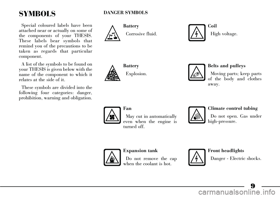
9
Battery
Corrosive fluid.
SYMBOLS
Special coloured labels have been
attached near or actually on some of
the components of your THESIS.
These labels bear symbols that
remind you of the precautions to be
taken as regards that particular
component.
A list of the symbols to be found on
your THESIS is given below with the
name of the component to which it
relates at the side of it.
These symbols are divided into the
following four categories: danger,
prohibition, warning and obligation.DANGER SYMBOLS
Battery
Explosion.
Fan
May cut in automatically
even when the engine is
turned off.
Expansion tank
Do not remove the cap
when the coolant is hot.
Coil
High voltage.
Belts and pulleys
Moving parts; keep parts
of the body and clothes
away.
Climate control tubing
Do not open. Gas under
high-pressure.
Front headlights
Danger - Electric shocks.
Page 14 of 386
13
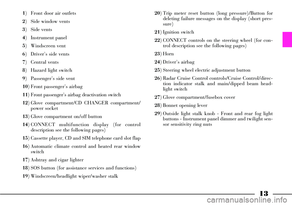
1) Front door air outlets
2) Side window vents
3) Side vents
4) Instrument panel
5) Windscreen vent
6) Driver’s side vents
7) Central vents
8) Hazard light switch
9) Passenger’s side vent
10) Front passenger’s airbag
11) Front passenger’s airbag deactivation switch
12) Glove compartment/CD CHANGER compartment/
power socket
13) Glove compartment on/off button
14) CONNECT multifunction display (for control
description see the following pages)
15) Cassette player, CD and SIM telephone card slot flap
16) Automatic climate control and heated rear window
switch
17) Ashtray and cigar lighter
18) SOS button (for assistance services and functions)
19) Windscreen/headlight wiper/washer stalk 20) Trip meter reset button (long pressure)/Button for
deleting failure messages on the display (short pres-
sure)
21) Ignition switch
22) CONNECT controls on the steering wheel (for con-
trol description see the following pages)
23) Horn
24) Driver’s airbag
25) Steering wheel electric adjustment button
26) Radar Cruise Control controls/Cruise Control/direc-
tion indicator stalk and main/dipped beam head-
light switch
27) Glove compartment/fusebox cover
28) Bonnet opening lever
29) Outside light stalk knob - Front and rear fog light
buttons - Instrument panel dimmer and twilight sen-
sor sensitivity ring nuts
Page 103 of 386
102
The wiper stops working a few
strokes after releasing the stalk; a
further “cleaning stroke”, after a
few seconds completes the wiping
operation.
Windscreen washer nozzles are fit-
ted with demisting resistors that cut
in automatically (for about 3 min-
utes) when pressing the fast window
demisting/defrosting button.
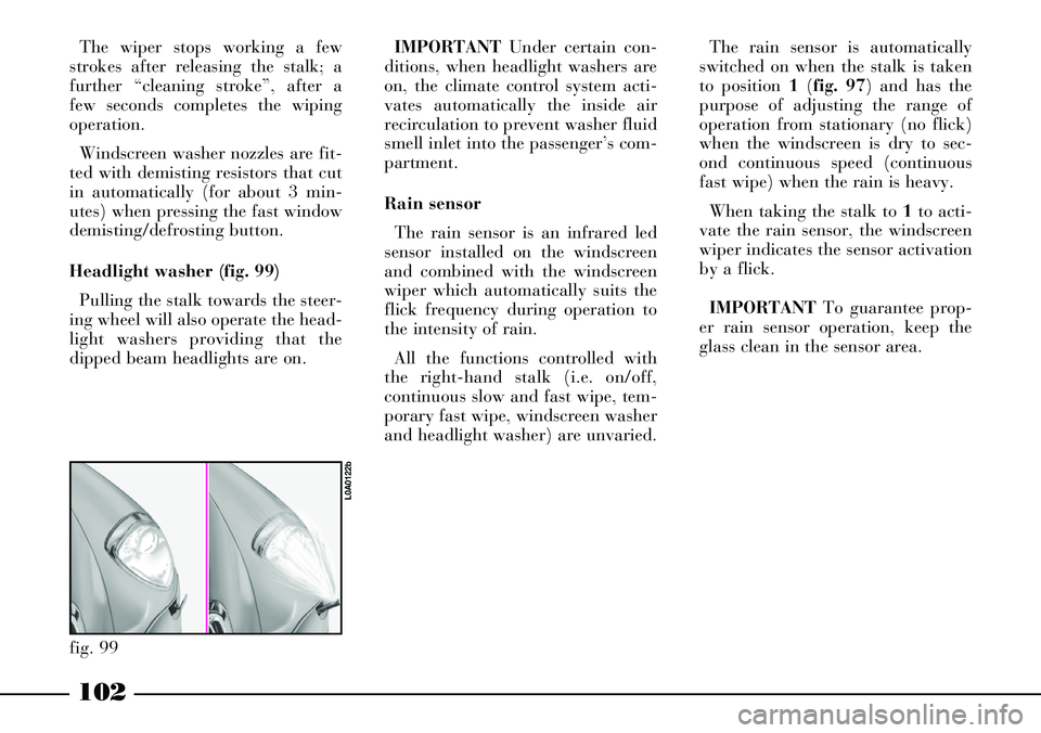
Headlight washer (fig. 99)
Pulling the stalk towards the steer-
ing wheel will also operate the head-
light washers providing that the
dipped beam headlights are on.IMPORTANTUnder certain con-
ditions, when headlight washers are
on, the climate control system acti-
vates automatically the inside air
recirculation to prevent washer fluid
smell inlet into the passenger’s com-
partment.
Rain sensor
The rain sensor is an infrared led
sensor installed on the windscreen
and combined with the windscreen
wiper which automatically suits the
flick frequency during operation to
the intensity of rain.
All the functions controlled with
the right-hand stalk (i.e. on/off,
continuous slow and fast wipe, tem-
porary fast wipe, windscreen washer
and headlight washer) are unvaried.
fig. 99
L0A0122b
The rain sensor is automatically
switched on when the stalk is taken
to position 1(fig. 97) and has the
purpose of adjusting the range of
operation from stationary (no flick)
when the windscreen is dry to sec-
ond continuous speed (continuous
fast wipe) when the rain is heavy.
When taking the stalk to 1to acti-
vate the rain sensor, the windscreen
wiper indicates the sensor activation
by a flick.
IMPORTANTTo guarantee prop-
er rain sensor operation, keep the
glass clean in the sensor area.
Page 108 of 386

107
INSTRUMENTS
SPEEDOMETER (fig. 103)
The speedometer shows the car
speed expressed in kilometres per
hour (km/h) and starts signalling
the speed when the car speed
exceeds approx. 4 km/h (see the
indications given in paragraph “At
the filling station").REV COUNTER (fig. 104)
If the needle is in the hazard sector
(the section with red lines) it shows
that the engine is over-revving. Do
not travel with the needle in this sec-
tor.
When the engine is idling, the rev
counter may show a gradual or sud-
den increase in engine speed,
according to the case. This is normal
and indicates the operation of the
climate control compressor or fans,
etc. In particular, a gradual varia-
tion in engine revolution speed safe-
guards battery charge.IMPORTANTThe hazard sectors
can present different widths and dif-
ferent full scale values according to
the various car versions.
IMPORTANTThe electronic injec-
tion control system will progressive-
ly cut off the flow of fuel when the
engine is over-revving and the
engine will consequently lose power.
fig. 103
L0A0232b
fig. 104
L0A0233b
Page 143 of 386

142
CLIMATE CONTROL SYSTEM
fig. 112
L0A0002b
Page 144 of 386

143
1- Windscreen defrosting/demist-
ing vents
2- Front side windows defrost-
ing/demisting vents
3- Central directional and
adjustable vents
4- Side directional and adjustable
vents
5- Air vents on driver side
6- Air vents on passenger side
7- Directional and adjustable
vents on front doors
8- Front footwell air vents
9- Rear footwell air vents
10- Rear central directional and
adjustable vents
11- Rear side directional and
adjustable ventsThe climate control system can be
operated in one of the following
ways:
– manually, by selecting the func-
tions by means of the control panel
buttons;
– automatically, by means of the
system electronic control unit.The air is let into the passenger
compartment through a set of vents
on the dashboard, on the front door
panels, on the rear central tunnel, on
door posts and on the floor as shown
in (fig. 112).
Page 146 of 386

AIR VENTS
The car is fitted with three air
vents set on the dashboard: two
vents A(fig. 118) on driver side and
one B (fig. 119) on passenger side,
sending air in the passenger com-
partment in a “diffused” mode.
This particular function conveys air
at low speed, about half of the usual
flow, through additional vents.
Moreover, it reduces the air impact
on the passengers and the noise due
to the air coming out of the vents,
thus improving the passengers' com-
fort.IMPORTANTWhen the outside
temperature is very high (over 30°C),
to reach the selected temperature as
soon as possible, it is suggested to op-
erate air vents only after the system
has reached steady working condi-
tions.
IMPORTANTOn versions equipped
with solar cell operated sunroof
(where provided), to check operation
at first speed of climate control sys-
tem fan when the car is parked, dis-
engage air vents and set air distribu-
tion from central dashboard vents
only before leaving the car.
fig. 119
L0A0060b
fig. 120
L0A0059b
fig. 118
L0A0061b
145
Air vents (open) are actually used
only when the control for directing
air flow on the instrument panel is
operated.
Air vents are opened by rotating
the dashboard central vent knobs
beyond the upper stop limit (fig.
120):
– control Afor air vents on driver
side
– control Bfor air vent on passen-
ger side.
At the stop limit of these controls
there is a button which, if pressed,
sends a signal to the climate system
control unit.
Page 147 of 386

146
AUTOMATIC
CLIMATE
CONTROL SYSTEM
GENERAL
The car can be equipped with a
two-zone or multi-zone automatic
climate control system.
The two-zone climate control sys-
tem controls temperature, air distri-
bution and flow inside the passenger
compartment in two areas: driver
side and passenger side.
The multi-zone climate control sys-
tem controls temperature, air distrib-
ution and flow inside the passenger
compartment in three areas: driver
side, passenger side or back-seat pas-
sengers.
Control of front-seat passenger and
back-seat passengers is alternated;
when the button led REARis turned
off, the front-seat passenger control
is operating, whereas when button
REARis pressed (button led turned
on), the back control panel is acti-
vated, thus excluding those for the
front-seat passenger.Temperature check is based on the
“heat balance” concept, which
means that the system works con-
stantly to keep a regular balance
between incoming and outgoing heat
energy, in order to stabilize temper-
ature inside the passenger compart-
ment and compensate possible vari-
ations of outside climate, sun radi-
ance included. For optimal control
of temperature in the two areas of
the passenger compartment, the sys-
tem is equipped with a sun ray sen-
sor.
The system features a pollution
sensor which can automatically
switch the air recirculation function
on to reduce the unpleasant effects
of polluted air in cities, queues, tun-
nels and when the windscreen wash-
er is operated (with the characteris-
tic smell of alcohol).
The air quality is controlled by an
active carbon dust/pollen filter
which has the double function of
mechanically filtering the particles
dispersed in the air and attenuating
the peak accumulation of certain
pollutants.Parameters and functions auto-
matically controlled are the follow-
ing:
– temperature of air let into dri-
ver/passenger vents (front-seat/
back-seats);
– air distribution to vents on dri-
ver/passenger side (front-seat/
back-seats);
– fan speed (continuos variation of
air flow);
– compressor activation (to cool
air);
– air recirculation.
All these functions can be adjusted
manually, it means that one or more
system functions can be selected and
that it is possible to change their
parameters. However, in this way
the system is unable to control man-
ually selected functions which will
be changed by the system only for
safety reasons, while keeping the
required temperature.
Page 148 of 386
147
IMPORTANTDuring air distribu-
tion automatic management, all the
air distribution button leds are off.
User can select manually any distri-
bution, and only in this case, the
concerned button led will be lit.
The manual settings have priority
over the automatic settings until the
user returns the system to automatic
control.
Manual setting of a function does
not compromise automatic control
of the other functions.
The amount of air let into the pas-
senger compartment does not
depend on the car speed. It is in fact
adjusted by an electronically con-
trolled fan.
The temperature of the air let into
the passenger compartment is
always controlled automatically
(unless the system is off), according
to the temperatures set on the dri-
ver’s and front/rear passenger’s dis-
plays.The following parameters and
functions can be adjusted manually:
– air temperature on driver/pas-
senger side (front/rear);
– fan speed (continuous variation);
– air distribution in seven positions
(driver/passengers);
– diffused air distribution;
– compressor activation;
– priority of one-zone/two-zone
distribution (front/back);
– rapid defrosting/demisting func-
tion;
– air recirculation;
– automatic/manual system con-
trol;
– heated rear window;
– system off;
– activation of back control panel.
The defrosting/demisting function
includes a set of operations enabling
to defrost/demist rapidly both the
windscreen and the heated rear win-
dow.At each turning off, the system
after storing control and function
conditions, sets up the open recircu-
lation, thus creating the necessary
conditions for operation at first
speed of climate control system fan
at parking, fed by solar cell operated
sunroof (where provided).
IMPORTANTBest operation of
climate control system fan at park-
ing, fed by solar cell operated sun-
roof (where provided), is obtained
by closing completely the windows
and sunroof. Furthermore, to check
operation at first speed of climate
control system fan when the car is
parked, disengage air vents and set
air distribution from central dash-
board vents only before leaving the
car.
When turning on, the system
restores the conditions memorized
before turning off, except for the
rapid defrosting/demisting function
which is reset.