dashboard Lancia Thesis 2006 Owner handbook (in English)
[x] Cancel search | Manufacturer: LANCIA, Model Year: 2006, Model line: Thesis, Model: Lancia Thesis 2006Pages: 386, PDF Size: 8.69 MB
Page 13 of 386
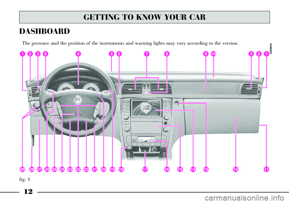
12
fig. 1
DASHBOARD
The presence and the position of the instruments and warning lights may vary according to the version.
L0A0001b
GETTING TO KNOW YOUR CAR
Page 25 of 386
It is absolutely forbidden
to carry out whatever af-
ter-market operation in-
volving steering system or steering
column modifications (e.g.: instal-
lation of anti-theft Device) that
could badly affect performance
and safety, cause the lapse of war-
ranty and also result in non-com-
pliance of the car with homologa-
tion requirements.
24
STEERING COLUMN LOCK
The steering column lock is
engaged automatically after remov-
ing the ignition key.IGNITION
SWITCH
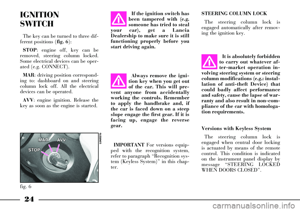
The key can be turned to three dif-
ferent positions (fig. 6):
STOP: engine off, key can be
removed, steering column locked.
Some electrical devices can be oper-
ated (e.g. CONNECT).
MAR: driving position correspond-
ing to: dashboard on and steering
column lock off. All the electrical
devices can be operated.
AVV: engine ignition. Release the
key as soon as the engine is started.If the ignition switch has
been tampered with (e.g.
someone has tried to steal
your car), get a Lancia
Dealership to make sure it is still
functioning properly before you
start driving again.
Always remove the igni-
tion key when you get out
of the car. This will pre-
vent anyone from accidentally
working the controls. Remember
to apply the handbrake and, if
the car is faced down on a steep
slope engage the first gear. If it is
facing up, engage the reverse
gear.
IMPORTANTFor versions equip-
ped with the recognition system,
refer to paragraph “Recognition sys-
tem (Keyless System)” in this chap-
ter.
fig. 6
L0A0021b
Versions with Keyless System
The steering column lock is
engaged when central door locking
is actuated by means of the remote
control. This condition is indicated
on the instrument panel display by
message “STEERING LOCKED
WHEN DOORS CLOSED”.
Page 32 of 386
31
Remote control
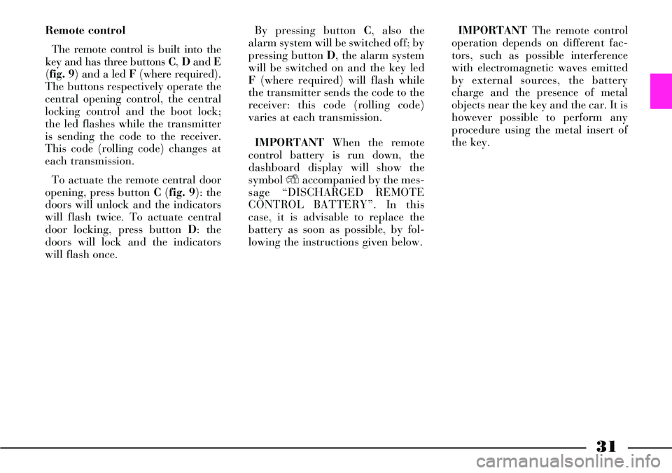
The remote control is built into the
key and has three buttons C, Dand E
(fig. 9) and a led F (where required).
The buttons respectively operate the
central opening control, the central
locking control and the boot lock;
the led flashes while the transmitter
is sending the code to the receiver.
This code (rolling code) changes at
each transmission.
To actuate the remote central door
opening, press button C (fig. 9): the
doors will unlock and the indicators
will flash twice. To actuate central
door locking, press button D: the
doors will lock and the indicators
will flash once.By pressing button C, also the
alarm system will be switched off; by
pressing button D, the alarm system
will be switched on and the key led
F(where required) will flash while
the transmitter sends the code to the
receiver: this code (rolling code)
varies at each transmission.
IMPORTANTWhen the remote
control battery is run down, the
dashboard display will show the
symbol Yaccompanied by the mes-
sage “DISCHARGED REMOTE
CONTROLBATTERY”. In this
case, it is advisable to replace the
battery as soon as possible, by fol-
lowing the instructions given below.IMPORTANTThe remote control
operation depends on different fac-
tors, such as possible interference
with electromagnetic waves emitted
by external sources, the battery
charge and the presence of metal
objects near the key and the car. It is
however possible to perform any
procedure using the metal insert of
the key.
Page 47 of 386
46
IMPORTANTDo not remove the
battery from the CID device until
when its replacement is possible.
Where system is unable to identify
the CID device (e.g. the CID battery
is flat) the car can be accessed by
using the emergency key existing
inside the CID itself.
When switched on, the alarm sys-
tem will be actuated when the door
is opened and the siren will start
sounding but will be switched off by
turning the starting knob to MAR.
Car start-up will moreover be possi-
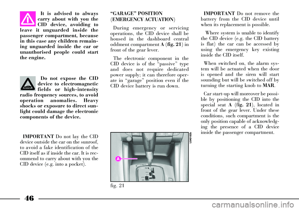
ble by positioning the CID into the
special seat A(fig. 21), located in
front of the gear lever. Under these
conditions, such compartment is the
only position capable of acknowledg-
ing the presence of a CID device
inside the passenger compartment.
fig. 21
L0A0182b
It is advised to always
carry about with you the
CID device, avoiding to
leave it unguarded inside the
passenger compartment, because
in this case any children remain-
ing unguarded inside the car or
unauthorised people could start
the engine.
Do not expose the CID
device to electromagnetic
fields or high-intensity
radio frequency sources, to avoid
operation anomalies. Heavy
shocks or exposure to direct sun-
light could damage the electronic
components of the device.
IMPORTANTDo not lay the CID
device outside the car on the sunroof,
to avoid a fake identification of the
CID itself as if inside the car. It is rec-
ommend to carry about with you the
CID device (e.g. into a pocket). “GARAGE” POSITION
(EMERGENCY ACTUATION)
During emergency or servicing
operations, the CID device shall be
housed in the dashboard central
oddment compartment A(fig. 21) in
front of the gear lever.
The electronic component in the
CID device is of the “passive” type
and does not require dedicated
power supply; it can therefore oper-
ate in “garage” position even if the
CID device battery is run down.
Page 89 of 386
88
FRONT AND SIDE
AIRBAGS
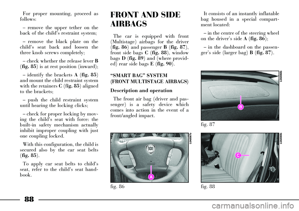
The car is equipped with front
(Multistage) airbags for the driver
(fig. 86) and passenger B(fig. 87),
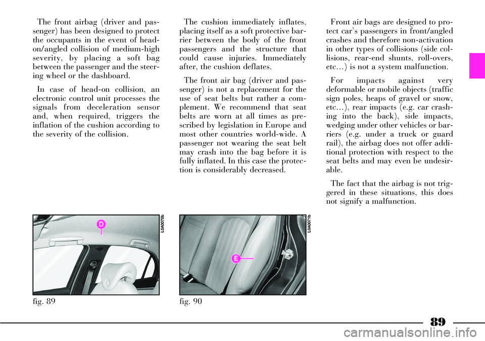
front side bags C (fig. 88), window
bags D(fig. 89) and (where provid-
ed) rear side bags E(fig. 90).
“SMART BAG” SYSTEM
(FRONT MULTISTAGE AIRBAGS)
Description and operation
The front air bag (driver and pas-
senger) is a safety device which
comes into action in the event of a
front/angled impact.
fig. 86
L0A0067b
For proper mounting, proceed as
follows:
– remove the upper tether on the
back of the child's restraint system;
– remove the black plate on the
child's seat back and loosen the
three knob screws completely;
– check whether the release lever B
(fig. 85) is at rest position (inward);
– identify the brackets A(fig. 85)
and mount the child restraint system
with the retainers C(fig. 85) aligned
to the brackets;
– push the child restraint system
until hearing the locking clicks;
– check for proper locking by mov-
ing the child's seat with force: the
built-in safety mechanism actually
inhibit improper coupling with just
one coupling locked.
With this configuration, the child is
secured also by the car seat belts
(fig. 85).
To apply car seat belts to child's
seat, refer to the child's seat hand-
book.It consists of an instantly inflatable
bag housed in a special compart-
ment located:
– in the centre of the steering wheel
on the driver’s side A (fig. 86);
– in the dashboard on the passen-
ger’s side (larger bag) B(fig. 87).
fig. 87
L0A0068b
fig. 88
L0A0069b
Page 90 of 386
89
The front airbag (driver and pas-
senger) has been designed to protect
the occupants in the event of head-
on/angled collision of medium-high
severity, by placing a soft bag
between the passenger and the steer-
ing wheel or the dashboard.
In case of head-on collision, an
electronic control unit processes the
signals from deceleration sensor
and, when required, triggers the
inflation of the cushion according to
the severity of the collision.
fig. 89
L0A0070b
The cushion immediately inflates,
placing itself as a soft protective bar-
rier between the body of the front
passengers and the structure that
could cause injuries. Immediately
after, the cushion deflates.
The front air bag (driver and pas-
senger) is not a replacement for the
use of seat belts but rather a com-
plement. We recommend that seat
belts are worn at all times as pre-
scribed by legislation in Europe and
most other countries world-wide. A
passenger not wearing the seat belt
may crash into the bag before it is
fully inflated. In this case the protec-
tion is considerably decreased.
fig. 90
L0A0071b
Front air bags are designed to pro-
tect car’s passengers in front/angled
crashes and therefore non-activation
in other types of collisions (side col-
lisions, rear-end shunts, roll-overs,
etc…) is not a system malfunction.
For impacts against very
deformable or mobile objects (traffic
sign poles, heaps of gravel or snow,
etc…), rear impacts (e.g. car crash-
ing into the back), side impacts,
wedging under other vehicles or bar-
riers (e.g. under a truck or guard
rail), the airbag does not offer addi-
tional protection with respect to the
seat belts and may even be undesir-
able.
The fact that the airbag is not trig-
gered in these situations, this does
not signify a malfunction.
Page 91 of 386
90
SEVERE DANGER:
The car is
equipped with
front passenger’s airbag, do not
place the child restraint seat on
the front seat. The inflation of the
airbag could cause even fatal
injury. If required, always deacti-
vate the passenger’s front airbag
when a child seat is placed on the
front seat. The passenger’s seat
shall be set as backwards as pos-
sible to prevent accidental con-
tacts between the child restraint
system and the dashboard.
Although it may not be pre-
scribed by law, we recommend
reactivating the airbag as soon as
it is no longer necessary to carry
children to provide better protec-
tion to adult passengers.
AIRBAGPASSENGER’S FRONT AIRBAG
The passenger’s airbag was
designed and calibrated to protect a
person wearing seat belts.
When fully inflated the bag will fill
most of the space between the dash-
board and the passenger.MANUALLY DEACTIVATING
THE PASSENGER’S FRONT
AIRBAG
The passenger’s front airbag can be
deactivated if it is absolutely neces-
sary to carry a child in the front pas-
senger seat.
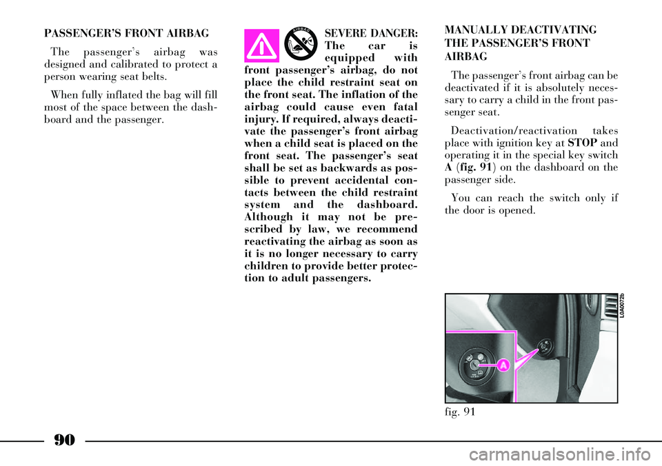
Deactivation/reactivation takes
place with ignition key at STOPand
operating it in the special key switch
A(fig. 91) on the dashboard on the
passenger side.
You can reach the switch only if
the door is opened.
fig. 91
L0A0072b
Page 98 of 386

97
LIGHT SWITCH
AND STEERING
COLUMN STALKS
The devices and services controlled
by light switch and steering column
stalks can only be activated with the
ignition key at MAR, excluding the
parking lights that are switched on
only with key at STOPor removed.
Outside lights can be switched on
manually or automatically accord-
ing to daylight intensity.LIGHT SWITCH (fig. 94)
It has 5 positions:
0- outside lights off
6- side/taillights
2- dipped beam headlights
F- parking lights
AUTO- automatic outside light
switching on/off according to set
sensitivity level.
Outside lights off
Outside lights are off when ring A
is turned to 0.
Side/taillights and number plate
lights
To switch these lights on, turn ring
Ato 6.
When these lights are on, instru-
ment panel warning light 3lights
up.
When the outside lights are turned
on, the instrument panel and the
various controls and displays located
on the dashboard and central con-
sole light up.Dipped beam headlights
These lights come on when you
turn ring Ato 2.
Parking lights
With ignition key at STOPor
removed, turn ring Ato Fto switch
the parking lights on (side/tail-
lights), the relevant instrument
panel warning light will come on.
When parking lights are on, move
the left stalk downwards to switch
on only the left side lights and move
it upwards to switch on only the
right side lights. In this case the
number plate lights and the instru-
ment panel warning light will not
come on.
When parking lights are on, a
buzzer will sound when opening the
driver’s door. Buzzer sound will stop
when closing the door or switching
the lights off.
fig. 94
L0A0199b
Page 144 of 386

143
1- Windscreen defrosting/demist-
ing vents
2- Front side windows defrost-
ing/demisting vents
3- Central directional and
adjustable vents
4- Side directional and adjustable
vents
5- Air vents on driver side
6- Air vents on passenger side
7- Directional and adjustable
vents on front doors
8- Front footwell air vents
9- Rear footwell air vents
10- Rear central directional and
adjustable vents
11- Rear side directional and
adjustable ventsThe climate control system can be
operated in one of the following
ways:
– manually, by selecting the func-
tions by means of the control panel
buttons;
– automatically, by means of the
system electronic control unit.The air is let into the passenger
compartment through a set of vents
on the dashboard, on the front door
panels, on the rear central tunnel, on
door posts and on the floor as shown
in (fig. 112).
Page 145 of 386
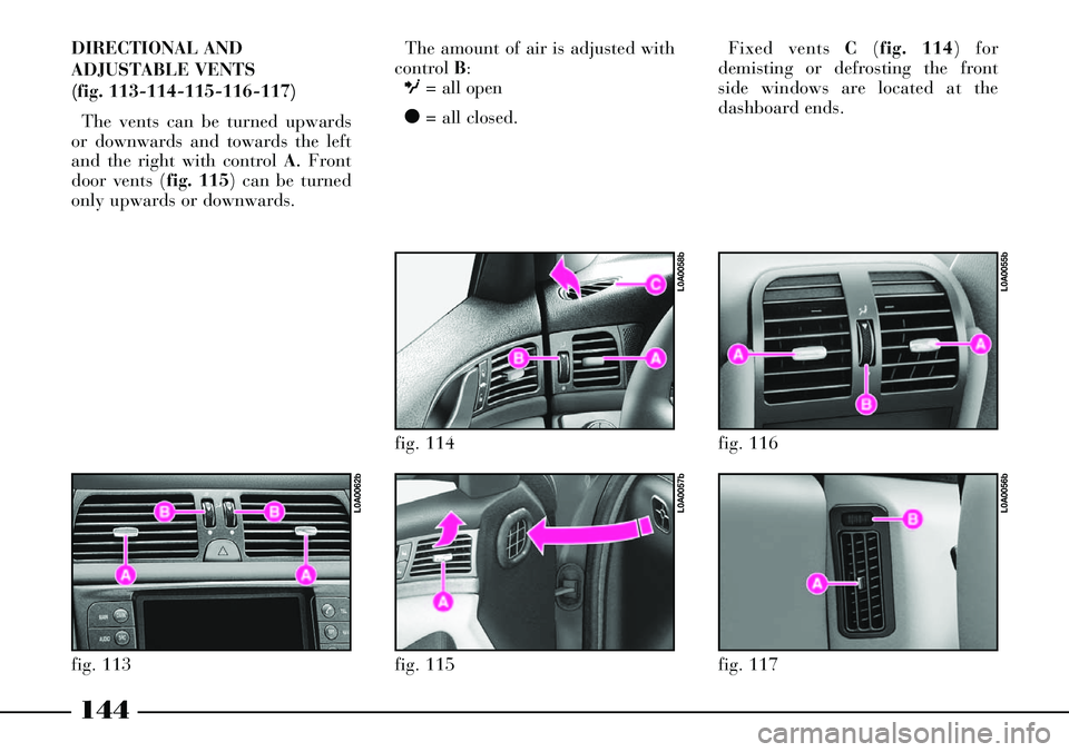
The amount of air is adjusted with
control B:
O= all open
ç= all closed.
fig. 117
L0A0056b
fig. 116
L0A0055b
144
DIRECTIONAL AND
ADJUSTABLE VENTS
(fig. 113-114-115-116-117)
The vents can be turned upwards
or downwards and towards the left
and the right with control A
.Front
door vents (fig. 115) can be turned
only upwards or downwards.
fig. 115
L0A0057b
fig. 114
L0A0058b
fig. 113
L0A0062b
Fixed vents C(fig. 114) for
demisting or defrosting the front
side windows are located at the
dashboard ends.