brake light Lancia Thesis 2007 Owner handbook (in English)
[x] Cancel search | Manufacturer: LANCIA, Model Year: 2007, Model line: Thesis, Model: Lancia Thesis 2007Pages: 386, PDF Size: 8.69 MB
Page 260 of 386

259
DRIVING ON SNOW AND ICE
– Here are some tips for driving in
these conditions:
– Keep your speed down.
– Use winter tyres or snow chains
for driving on snow covered roads;
see the respective paragraphs in this
chapter.
– Prevalently use the engine brake
and avoid sudden braking.
– Do not accelerate suddenly and
avoid swerving.
– In winter, even apparently dry
roads may have icy patches. Be care-
ful therefore when driving over
stretches that do not get much expo-
sure to the sun or are lined with trees
or rocks where ice might not have
melted.
– Keep a good distance from the
vehicles in front.DRIVING WITH ABS
The ABS is a braking system that
essentially offers two advantages:
1) It prevents wheel lock and con-
sequent skidding in emergency
stops, particularly when the road
does not offer much grip.
2) It makes possible to brake and
steer at the same time so you can
avoid unexpected obstacles and
direct the car where you want while
braking.
To get the most out of ABS:
– During emergency stops or when
grip conditions are very poor, you
will feel a slight pulsation on the
brake pedal. This is the sign that the
ABS is working. Do not release the
brake pedal but continue to press so
as not to interrupt the braking
action.– The ABS prevents the wheels
from locking, but it does not
increase actual grip conditions
between tyre and road. Therefore,
even if your car is fitted with ABS,
keep a safe distance from the car in
front of you and keep your speed
down when driving into bends.
ABS serves to increase your control
over the car, not to enable you to go
faster.
Page 266 of 386

265
TOW HITCH INSTALLATION
The tow hitch must be fixed to the
body by an expert in accordance
with the following instructions and
respecting the additional and/or
integrative information provided by
the tow hitch manufacturer.
The tow hitch to be fitted must
comply with the current regulations
in force, with reference to Directive
94/20/EEC and subsequent modifi-
cations.
Use a tow hitch suited for the max-
imum towable load of the car ver-
sion on which the tow hitch is to be
fitted.
Use a unified coupling for the elec-
trical connections. The coupling is
generally fitted on a specific mount
fastened to the tow hitch. A specific
trailer lights control unit shall be
installed on the car.For the electric connections, a 7
pole 12VDC coupling must be used
(CUNA/UNI and ISO/DIN stan-
dards). Follow the instructions pro-
vided by the manufacturer of the car
and/or the tow hitch.
The electrical brake (where rele-
vant) or other device (electrical
winch, etc.) must be powered direct-
ly from the battery by means of a
lead with a cross-section area no
smaller than 2.5 mm
2.
IMPORTANTUse the electrical
brake or winch only when the engine
is running.
In addition to the electrical connec-
tions, only the power wire for an
additional electrical brake and for
internal trailer lighting with a power
not exceeding 15W can be connect-
ed to the car’s electrical system.
For connections use the specific
control unit with battery cable not
less than 2.5 mm
2.INSTALLATION DIAGRAM (fig. 1)
Fasten the tow hitch in the points
marked with (1) using 18 M10
screws and, in the points marked
with (2) use four M8 screws.
Fasten the tow hitch to the body
avoiding any type of drilling and
trimming of the rear bumpers that
remains visible when the tow hitch is
removed.
IMPORTANTFasten a tag in a
clearly visible position at the same
height as the tow hitch. The tag is
compulsory. It must be adequately
sized, made of suitable material and
carry the following information:
MAX LOAD ON BALL COUPLING
75 kg.
After assembly, seal the fastening
screws holes to prevent exhaust fumes
from entering the passenger compart-
ment.
Page 270 of 386

269
USING THE CAR AGAIN
Before using the car again after a
prolonged period of inactivity, the
following operations are recom-
mended:
– Do not dry-dust the car body.
– Check for fluid leaks (oil, brake
and clutch fluid, engine coolant
etc.).
– Change engine oil and filter.
– Check the level of:
– brake and clutch fluid
– engine coolant.
– Check the air cleaner and change
it, if required.
– Check the tyre pressure and the
tyres for signs of damage, cuts or
cracks. If this is the case, have them
replaced.
– Check the engine belt conditions.STORING THE CAR
The following precautions should
be taken if the car will not be used
for several months:
– Park the car in covered, dry and
if possible well-ventilated premises.
– Engage a gear.
– If the car is parked on flat
ground, disengage the electric park-
ing brake as described in the rele-
vant paragraph.
– Clean and protect the painted
parts using protective wax.
– Sprinkle talcum powder on the
rubber windscreen and rear window
wiper blades and lift them off the
glass.
– Slightly open the windows.
– Inflate the tyres to 0.5 bar above
the normal specified pressure, lean
them on wood boards, if possible
and check it at intervals.– Do not switch the electronic
alarm system on.
– Remove the negative cable (-)
from the battery terminal and check
the battery charge. This check
should be performed every month if
the car is to be stored for long peri-
ods. Recharge the battery if it falls
below 12.5V.
IMPORTANT Before opening the
luggage compartment bonnet to dis-
connect the battery, carefully read
and comply with instructions con-
tained in the paragraph “If battery is
to be disconnected” in the chapter
“In an emergency”.
– Do not drain the engine cooling
system.
– Cover the car with a cloth or per-
forated plastic sheet. Do not use
sheets of non-perforated plastic as
they do not allow moisture on the
body to evaporate.
Page 274 of 386

273
7) Start the engine.
8) When the engine has started,
remove the leads in the reverse order
to before: D, C, Band finally A.
IMPORTANT If the engine fails to
start after a few attempts, do not keep
turning the key but have the car seen
to at a Lancia Dealership.
9) Put the cover back on the bat-
tery positive terminal by fitting the
lock flanges in.
10) Put the cover back and retight-
en the knob.
11) Close the boot tailgate.IMPORTANTWhen the tailgate is
closed, the boot latch is not locked.
To lock it, turn the metal insert of
the key anticlockwise in the latch.
Do not carry out this
procedure if you lack
experience: if it is not
done correctly it can cause very
intense electrical discharges and
the battery might even explode.
Do not to put naked flames or
lighted cigarettes near the battery
and do not cause sparks: risk of
explosion and fire.
Never use a battery
charger to jump start the
engine: you could damage
the electronic system, with spe-
cial reference to ignition and
injection control unit.
BUMP STARTING
Do not bump start by pushing,
towing or coasting downhill. This
way of starting could cause a rush of
fuel into the catalytic converter and
damage it beyond repair.
Remember that ifthe engine is not
running, the brake booster and the
power steering will not work. You
therefore have to use considerably
more effort on both the brake pedal
and the steering wheel.
Never connect the nega-
tive terminals of the two
batteries directly: sparks
could ignite the flammable gas
from the battery. If the auxiliary
battery is installed on another
car, prevent accidental contact
between the metal parts of the
two vehicles.
Page 284 of 386

283
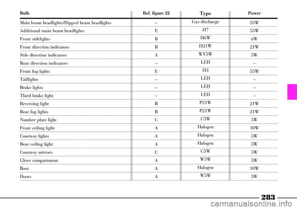
Bulb
Main beam headlights/Dipped beam headlights
Additional main beam headlights
Front sidelights
Front direction indicators
Side direction indicators
Rear direction indicators
Front fog lights
Taillights
Brake lights
Third brake light
Reversing light
Rear fog lights
Number plate light
Front ceiling light
Courtesy lights
Rear ceiling light
Courtesy mirrors
Glove compartment
Boot
Doors
Power
35W
55W
6W
21W
5W
–
55W
–
–
–
21W
21W
5W
10W
5W
5W
5W
5W
10W
5W
Type
Gas-discharge
H7
H6W
H21W
WY5W
LED
H3
LED
LED
LED
P21W
P21W
C5W
Halogen
Halogen
Halogen
C5W
W5W
Halogen
W5W
Ref. figure 22
–
E
B
B
A
–
E
–
–
–
B
B
C
A
A
A
C
A
A
A
Page 287 of 386

286
REAR LIGHT CLUSTER (fig. 26)
Taillights, direction indicators and
brake lights consists of leds built-
into the rear light cluster.
If the lights break down partially
or completely go to a Lancia
Dealership.REVERSING LIGHT AND REAR
FOG LIGHTS
Reversing lights and rear fog lights
are housed in the tailgate.
To replace the bulbs:
1) Open the tailgate and lift the
covering A(fig. 27) near the bulb to
be replaced.
2) Loosen the screw Band remove
the bulb holder C.3) Remove the clipped in glass
bulbs (fig. 28).
D- B type, 12V-P21W bulb for
reversing light.
E- B type, 12V-P21W bulb for
rear fog light.
4) After replacing the bulbs, refit
the bulb holder and fasten it with
the screw.
5) Lower the tailgate cover.
fig. 26
L0A0123b
fig. 27
L0A0124b
fig. 28
L0A0125b
Page 288 of 386

287
NUMBER PLATE LIGHTS
(fig. 29)
To replace the bulb:
1) Remove the lens using a screw-
driver as a lever in point A.
2) Remove the bulb Bby releasing
the side contacts and then replace it.
3) Refit the lens by inserting it first
from side Cand then by pressing it
on the other side until it fits.ADDITIONAL BRAKE LIGHT
(THIRD BRAKE LIGHT)(fig. 30)
If the third brake light breaks
down partially or completely go to a
Lancia Dealership.IF AN INTERIOR
BULB BURNS OUT
FRONT CEILING LIGHT
To replace the bulbs:
1) Remove the clipped in caps A
and B (fig. 31) by levering with a
screwdriver on the external part.
fig. 29
L0A0126b
fig. 30
L0A0287b
fig. 31
L0A0129b
Page 297 of 386

296
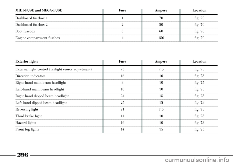
MIDI-FUSE and MEGA-FUSE
Dashboard fusebox 1
Dashboard fusebox 2
Boot fusebox
Engine compartment fusebox
Fuse
1
2
3
4
Ampere
70
50
60
150
Location
fig. 70
fig. 70
fig. 70
fig. 70
Exterior lights
External light control (twilight sensor adjustment)
Direction indicators
Right-hand main beam headlight
Left-hand main beam headlight
Right-hand dipped beam headlight
Left-hand dipped beam headlight
Reversing light
Third brake light
Hazard lights
Front fog lights
Fuse
23
16
8
10
24
25
21
14
16
14
Ampere
7.5
10
10
10
15
15
7.5
10
10
15
Location
fig. 73
fig. 73
fig. 75
fig. 75
fig. 73
fig. 73
fig. 73
fig. 73
fig. 73
fig. 75
Page 299 of 386

298
Devices and utilities
Horn
Windscreen wiper controls
Brake light control (NC)
Brake light control (NA)
Ignition switch
Air conditioner compressor
Cruise Control (satellite controls)
Cruise Control (Adaptive point)
Climate control system fan
Engine cooling electric fan (first)
Engine cooling electric fan (second)
Right-hand headlight (control unit)
Left-hand headlight (control unit)
Diesel fuel filter (PTC)
Electronic injection system
Injectors (diesel versions)
Driving position point interface
Automatic transmission point interface
Climate control system point interface
Fuse
11
23
20
14
7
12
20
20
5
3
4
10
10
16
13
19
14
15
23
6
15
Ampere
15
7.5
7.5
10
20
7.5
7.5
7.5
40
60
20
7.5
7.5
20
7.5
20
20
10
7.5
10
7.5
Location
fig. 75
fig. 73
fig. 73
fig. 73
fig. 75
fig. 75
fig. 73
fig. 73
fig. 75
fig. 75
fig. 78
fig. 78
fig. 78
fig. 75
fig. 75
fig. 75
fig. 78
fig. 78
fig. 73
fig. 73
fig. 73
Page 300 of 386

299
Devices and utilities
Engine control system point interface
Brake system point interface
Headlight washers
Heated rear window
Automatic gearbox starter
NIM
Passenger position point
Steering lock point
Brake Assistant point
(*) As an alternative for certain versions/markets
Braking system point (NFR 1)
Braking system point (NFR 2)
Infotelematic point
Yaw Lateral point
(*) As an alternative for certain versions/markets
Keyless System point
Driver door point
Driver door point (power supply)
Passenger door point
Fuse
22
29
15
17
17
6
14
22
19 (*)
13 (*)
19
1
6
6
19 (*)
13 (*)
19
22
11
8
11
23
Ampere
7.5
7.5
20
30
30
10
10
10
10
10
7.5
40
40
10
10
10
7.5
10
20
20
20
7.5
Location
fig. 75
fig. 73
fig. 75
fig. 73
fig. 75
fig. 73
fig. 78
fig. 78
fig. 78
fig. 73
fig. 73
fig. 75
fig. 75
fig. 73
fig. 78
fig. 73
fig. 73
fig. 78
fig. 78
fig. 73
fig. 78
fig. 73