ECO mode Lancia Thesis 2007 Owner handbook (in English)
[x] Cancel search | Manufacturer: LANCIA, Model Year: 2007, Model line: Thesis, Model: Lancia Thesis 2007Pages: 386, PDF Size: 8.69 MB
Page 17 of 386
16
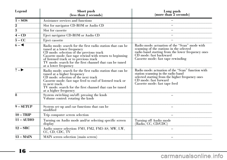
Legend
1 – SOS
2
3
4 – CD
5 – CC
6 – ¯
7 – ˙
8
9 – SETUP
10 – TRIP
11 – AUDIO
12 – SRC
13 – MAINShort push
(less than 2 seconds)
Assistance services and functions
Slot for navigator CD-ROM or Audio CD
Slot for cassette
Eject navigator CD-ROM or Audio CD
Eject cassette
Radio mode: search for the first radio station that can be
tuned at a lower frequency
CD mode: selection of the previous track
Cassette mode: fast tape rewind with return to beginning
of listened track or to previous track
TV mode: search for the first channel that can be tuned
at a lower frequency
Radio mode: search for the first radio station that can be
tuned at a higher frequency
CD mode: selection of the next track
Cassette mode: fast tape feed to end of listened track or
to next track.
TV mode: search for the first channel that can be tuned
at a higher frequency
System switching on/off: pressing the knob
Volume control: rotating the knob
System set-up and car functions that can be
modified
Trip computer screen selection
Turning on Audio mode and/or selecting specific screen
display
Audio source selection: FM1, FM2, FM3-AS, MW, LW,
CC, CD, CDC, TV
MAIN screen selection (main screen)Long push
(more than 2 seconds)
–
–
–
–
–
Radio mode: actuation of the “Scan” mode with
scanning of the stations in the selected
radio band starting from the lower frequency ones
CD mode: fast backward
Cassette mode: fast tape rewinding
Radio mode: actuation of the “Scan” function with
station scanning in the radio band
selected starting from the higher frequency ones
CD mode: fast forward
Cassette mode: fast tape feed
–
–
–
Turning off Audio mode
(Radio, CC, CD/CDC)
–
–
Page 18 of 386
17
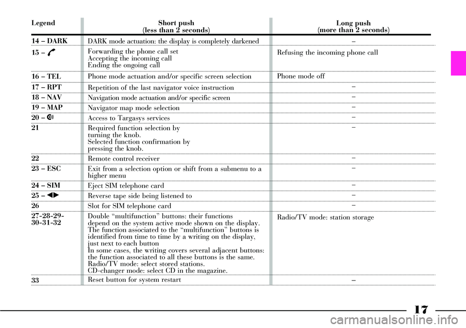
Legend
14 – DARK
15 –
£
16 – TEL
17 – RPT
18 – NAV
19 – MAP
20 – •
21
22
23 – ESC
24 – SIM
25 – ¯˙
26
27-28-29-
30-31-32
33Short push
(less than 2 seconds)
DARK mode actuation: the display is completely darkened
Forwarding the phone call set
Accepting the incoming call
Ending the ongoing call
Phone mode actuation and/or specific screen selection
Repetition of the last navigator voice instruction
Navigation mode actuation and/or specific screen
Navigator map mode selection
Access to Targasys services
Required function selection by
turning the knob.
Selected function confirmation by
pressing the knob.
Remote control receiver
Exit from a selection option or shift from a submenu to a
higher menu
Eject SIM telephone card
Reverse tape side being listened to
Slot for SIM telephone card
Double “multifunction” buttons: their functions
depend on the system active mode shown on the display.
The function associated to the “multifunction” buttons is
identified from time to time by a writing on the display,
just next to each button
In some cases, the writing covers several adjacent buttons:
the function associated to all these buttons is the same.
Radio/TV mode: select stored stations.
CD-changer mode: select CD in the magazine.
Reset button for system restart Long push
(more than 2 seconds)
–
Refusing the incoming phone call
Phone mode off
–
–
–
–
–
–
–
–
–
–
Radio/TV mode: station storage–
Page 19 of 386
18
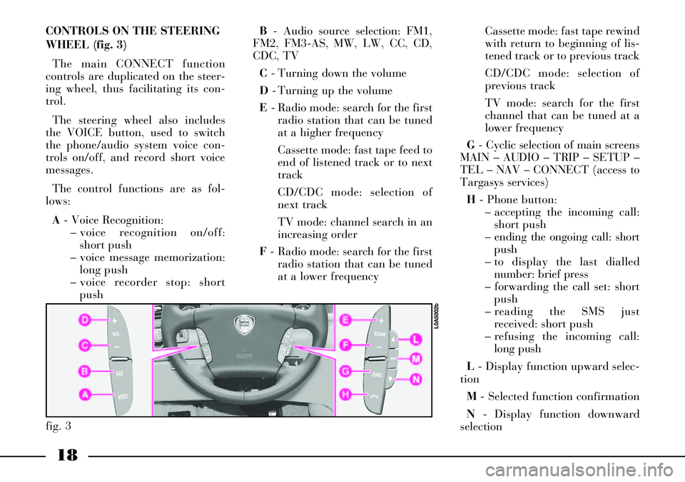
CONTROLS ON THE STEERING
WHEEL (fig. 3)
The main CONNECT function
controls are duplicated on the steer-
ing wheel, thus facilitating its con-
trol.
The steering wheel also includes
the VOICE button, used to switch
the phone/audio system voice con-
trols on/off, and record short voice
messages.
The control functions are as fol-
lows:
A- Voice Recognition:
– voice recognition on/off:
short push
– voice message memorization:
long push
– voice recorder stop: short
pushB- Audio source selection: FM1,
FM2, FM3-AS, MW, LW, CC, CD,
CDC, TV
C- Turning down the volume
D- Turning up the volume
E- Radio mode: search for the first
radio station that can be tuned
at a higher frequency
Cassette mode: fast tape feed to
end of listened track or to next
track
CD/CDC mode: selection of
next track
TV mode: channel search in an
increasing order
F- Radio mode: search for the first
radio station that can be tuned
at a lower frequencyCassette mode: fast tape rewind
with return to beginning of lis-
tened track or to previous track
CD/CDC mode: selection of
previous track
TV mode: search for the first
channel that can be tuned at a
lower frequency
G- Cyclic selection of main screens
MAIN – AUDIO – TRIP – SETUP –
TEL – NAV – CONNECT (access to
Targasys services)
H- Phone button:
– accepting the incoming call:
short push
– ending the ongoing call: short
push
– to display the last dialled
number: brief press
– forwarding the call set: short
push
– reading the SMS just
received: short push
– refusing the incoming call:
long push
L- Display function upward selec-
tion
M- Selected function confirmation
N- Display function downward
selection
fig. 3
L0A5002b
Page 64 of 386
63
Stored position are recalled only if
the required position is different
from the current one and is not pos-
sible when the car speed exceeds 10
km/h.
Seats can be moved only when the
ignition key is at MARand, for
about 1 minute, also after removing
the key or turning it to STOP: dur-
ing this time, the external rear view
mirrors will not move, but when the
car is started again, they will be
automatically realigned together
with the seat position (see paragraph
“Automatic realignment of external
rear view mirrors”).
If stored seat position recalling is
still in course after this time has
elapsed, recalling will be concluded
in any case.If the engine is started during the
recalling stage, seat moving will be
stopped; once this stage is over the
seat will return automatically to the
stored position.
IMPORTANTPressing any of
memorisation or adjustment buttons
during the recalling stage, causes the
immediate stop of the seat (antipan-
ic mode).
Storing the “parking” position of
the external rear view mirror on
passenger side
You can achieve better visibility
during manoeuvres in reverse gear
(for instance, when parking the car)
by adjusting the external passenger
rear view mirror to a different posi-
tion from the one normally used.
This position can be stored by the
driver.To store the position proceed as
follows:
– with the car stopped and the igni-
tion key at MAR, engage the reverse
gear;
– adjust the position of the external
passenger rear view mirror by means
of the respective controls so as to
obtain the optimum position for the
parking manoeuvre;
– press down for at least 3 seconds
any of buttons “1”, “2” or “3” (fig.
46) used to store/recall the seat posi-
tion;
– together with the “parking” posi-
tion of the external passenger side
rear view mirror, also the seat posi-
tion, the driver rear view mirror
position and the driving position of
the external passenger side rear view
mirror are stored.
A sound signal warns the driver
that the mirror position has been
stored.
Page 74 of 386
73
Improper use of the elec-
trical window winders can
be dangerous. Before and
during their operation ensure
that any passengers in the car are
not at risk from the moving glass
either by personal objects getting
caught in the mechanism or by
being injured by it directly.
Always remove the ignition key
when you get out of the car to
prevent the electrical window
winders being operated acciden-
tally and constituting a danger to
the people left in the car. IMPORTANT In the event that the
anti-trap function is activated 5
times in only 1 minute, the system
will automatically enter the “recov-
ery” mode (self-protection). This
condition is pointed out by the fact
that, in the closing phase, the win-
dow goes up in jerks.
It is therefore necessary in this case
to carry out the system restore pro-
cedure by operating window open-
ing control or turning the ignition
key to STOPand then to MAR.
Regular operation is restored if no
malfunction is present: otherwise
contact a Lancia Dealership.
In the event that the system detects
a malfunction, the failure message
and symbol ª!will appear on the
instrument panel display (see
“Window anti-trap safety system” at
paragraph “Warning lights”).ELECTRIC
WINDOWS
ANTI-TRAP SAFETY SYSTEM
Front and rear electric windows are
provided with anti-trap safety
device. When the system control unit
detects an obstacle in the window
closing travel, it makes the window
travel stop and reverse immediately.
This system complies with regula-
tion 2000/4/EC coming soon in
force, which is destined to protect
passengers leaning out of the win-
dows. Therefore, in case of unlawful
intrusions from the outside, the anti-
trap safety device could not activate.
Page 76 of 386
75
Pressing briefly the button the win-
dow “jerks”, whereas a prolonged
pressing makes the window opening
or closing in “automatic and continu-
ous” mode. When pressing again the
button the window stops in the
required position.
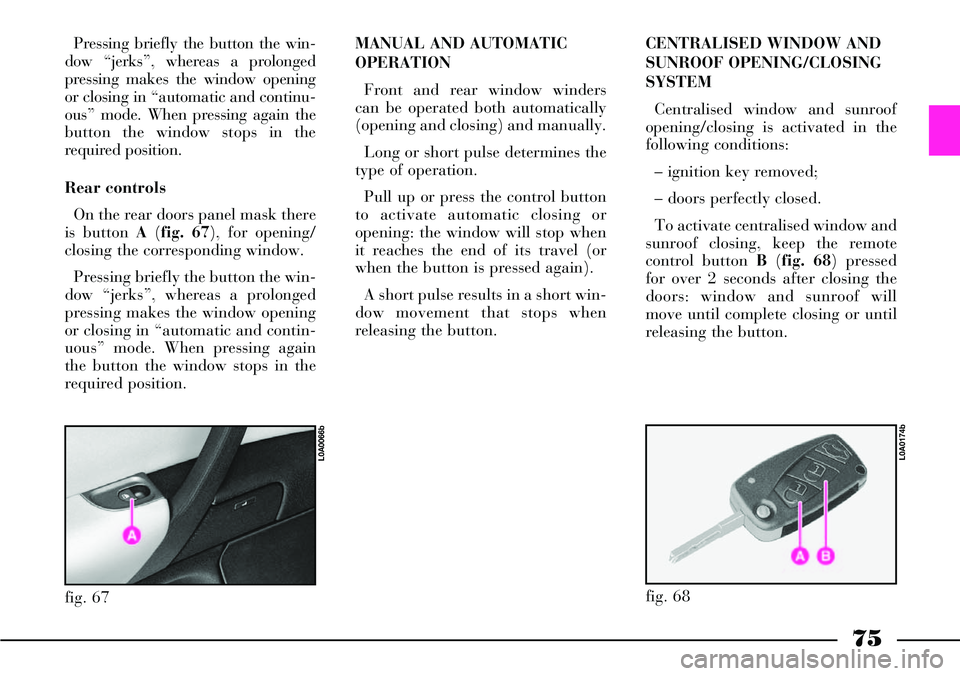
Rear controls
On the rear doors panel mask there
is button A (fig. 67), for opening/
closing the corresponding window.
Pressing briefly the button the win-
dow “jerks”, whereas a prolonged
pressing makes the window opening
or closing in “automatic and contin-
uous” mode. When pressing again
the button the window stops in the
required position.MANUAL AND AUTOMATIC
OPERATION
Front and rear window winders
can be operated both automatically
(opening and closing) and manually.
Long or short pulse determines the
type of operation.
Pull up or press the control button
to activate automatic closing or
opening: the window will stop when
it reaches the end of its travel (or
when the button is pressed again).
A short pulse results in a short win-
dow movement that stops when
releasing the button.CENTRALISED WINDOW AND
SUNROOF OPENING/CLOSING
SYSTEM
Centralised window and sunroof
opening/closing is activated in the
following conditions:
– ignition key removed;
– doors perfectly closed.
To activate centralised window and
sunroof closing, keep the remote
control button B(fig. 68) pressed
for over 2 seconds after closing the
doors: window and sunroof will
move until complete closing or until
releasing the button.
fig. 67
L0A0066b
fig. 68
L0A0174b
Page 119 of 386
LOW BRAKE FLUID
LEVEL
Turning the ignition key
to MAR, the warning light turns on
but it should go off after a few sec-
onds.
The warning light comes on togeth-
er with the message “LOW BRAKE
FLUID LEVEL” on the multifunc-
tion display, when the level of the
brake fluid in the reservoir falls
below the minimum level, due to
possible leak in the circuit.
118
INJECTION SYSTEM
FAILURE
(where provided -
JTD versions)
In normal conditions, turning the
ignition key to MAR, the warning
light turns on but it should go off
after a few seconds.
If the warning light stays on or turns
on while travelling together with the
message “ENGINE CONTROL SYS-
TEM FAULT” on the multifunction
display, this indicates that the injec-
tion system is not working perfectly
with possible lack of performance,
poor handling and high consumption.
In these conditions it is possible to
continue driving without however
requiring heavy effort or high speed
from the engine. In any case, contact
a Lancia Dealershipas soon as
possible.
Do not use the car for long periods
at high speed with this warning light
on since this could result in serious
damages especially in case of irregu-
lar operation or misfiring.
Ux
Flashing- indicates the possibility
of damage to the catalyst (see
“EOBD system” in this chapter).
If the warning light flashes, it is
necessary to release the accelerator
pedal to lower the speed of the
engine until the warning light stops
flashing; continue driving at moder-
ate speed, trying to avoid driving
conditions that may cause further
flashing and contact a Lancia
Dealershipas soon as possible.
If, turning the ignition
key to MAR, the Uwarn-
ing light does not turn on
or if it turn on glowing steadily or
flashing when travelling, contact
a Lancia Dealership.
Page 152 of 386
151
HOW TO USE THE CLIMATE
CONTROL SYSTEM
The system can be switched on in
various ways. We recommend start-
ing by pressing the AUTObutton
and setting the required tempera-
tures on the display.
Since the system controls three
areas of the passenger compartment,
the driver and the front/back pas-
sengers can select different tempera-
ture values, with a maximum differ-
ence accepted by the system of 7 °
C.
In this way, the system will start
working fully automatically to reach
the required temperature as soon as
possible. It will maintain the tem-
perature by adjusting the amount
and distribution pattern of the air let
into the passenger compartment and
manage the recirculation function
and the climate control system com-
pressor.When the system is working auto-
matically, the only possible manual
functions are:
– MONO, to align air temperature
and distribution on the passenger
side or in the back-seat passengers’
area with that on the driver side;
– REAR, to activate the back con-
trol panel;
– √, to switch off the compressor:
in these conditions the system works
only as a heater;
– air recirculation, to keep recircu-
lation always turned on or off;
–-, for faster defrosting/demist-
ing the front windows, rear window,
external rearview mirrors and wind-
screen wiper nozzles;
– (,for defrosting/demisting the
heated rear window and external
rearview mirrors.The temperature, air distribution
and fan speed settings can be
changed at any time during auto-
matic system operation. The system
will automatically adjust to the new
request. When the system is fully
working in automatic mode (FULL
AUTO), if air distribution and/or
flow is changed, definition FULL
disappears. In this way functions
pass from the automatic mode to the
manual mode, until button AUTOis
pressed again. There is only one fan
speed for all the passenger compart-
ment areas and it can be changed
also by operating back controls,
when activated.
With one or more functions manu-
ally on, the air temperature let into
the passenger compartment is auto-
matically managed by the system
unless the climate control compres-
sor is off. In this condition, in fact,
the air inlet into the passenger com-
partment cannot have a lower tem-
perature than that of the external
air.
Page 164 of 386
163
– when the engine is running the
system works only in “supplemen-
tary heater” mode.
Regardless of the operating mode,
the start up procedure for the sup-
plementary heater, once it has been
activated, is the following:
1- Fan activation for comburant
air, for at least 30 seconds, to venti-
late and oxygenate the combustion
chamber. The fan speed is progres-
sively increased until the average
operating value is reached.
2- After about 30 seconds, the
heater control unit activates the
electric pump metering the fuel and
the comburant air fan is deactivated
for at least 3 seconds, in order to
facilitate fuel burning. A spark plug
starts combustion inside the heater.
3- At this point, there is a com-
bustion stabilizing phase which lasts
around 15 seconds, during which
the fan speed is kept at average
level.4- In the following 50 seconds the
control unit makes the fan reach
nearly its highest speed.
5- Once combustion has stabilized,
the heater control unit deactivates
the plug and the fan reaches its
maximum speed.
6- From now on the plug is used
by the system as a combustion and
flame sensor.
7- Regardless of the operating
mode, the heater extinction proce-
dure is always based on the combus-
tion chamber ventilation for about
30 seconds, in order to eliminate
completely any combustion remain-
der.
IMPORTANTAfter switching the
system off, both automatically or
manually, it can be switched on
again (ON) only approx. 3 minutes
after or when the CONNECT mes-
sage “COOLING DOWN” disap-
pears from the display. IMPORTANTAlthough in a lesser
quantity the heater burns fuel as the
engine. Therefore, to prevent poi-
soning and suffocation the supple-
mentary heater shall never be turned
on, even temporarily, in confined
areas like garages and workshops
not equipped with exhaust fans.
IMPORTANTThe heater must
always be turned off during refu-
elling and at filling stations to pre-
vent the risk of explosions.
IMPORTANTDo not park the car
over flammable materials like paper,
grass or dry leaves: risk of fire.
OPERATION WITH ENGINE
STATIONARY
“Programmable heater” mode
With this operating mode, the sys-
tem heats the engine coolant and the
passenger compartment before
starting the engine, it keeps air recir-
culation closed and activates air dis-
tribution to the windscreen and the
floor by operating the passenger
compartment fan.
Page 166 of 386
165
The “parked-car heater” mode is
automatically deactivated when one
of the following conditions takes
place:
– engine started
– limit time (around 30 minutes) of
heater and/or coolant pump func-
tioning overcome
– turn off requested by the user
through the CONNECT
– malfunction detected by the heater
control unit
– partial battery run-down or alter-
nator fault.
“Timer 1” and “Timer 2”
The “Timer” options shall be used
to programme two heater daily cycles;
for each cycle enter the time of acti-
vation and the length of operation
both with 5 minute intervals.
Each cycle cannot last more than 60
minutes. The default operation is 15
minutes. The timer works regardless
of the ignition key position.During heater operation, messages
referred to the following conditions
are shown on CONNECT display:
– fuel level in reserve (continue any-
way?)
– fuel level in reserve. Parked-car
heater has been switched off
– parked-car heater not operating
because of cooling down
– parked-car heater not operating
because external temperature is
higher than 20 °C
– parked-car heater not operating
because motor is on
– parked-car heater has been
switched off because of low voltage.IMPORTANTFor safety reasons,
the timer must be programmed/con-
firmed at any activation and con-
firmed not later than 24 hours since
programming. In addition, the user
must confirm every time the timer ac-
tivation. The timer does not automat-
ically correct standard time.
The timer can be in one of the fol-
lowing conditions:
– off: in this condition the timer is
programmable and parameters can be
loaded or adjusted. Loaded parame-
ters should be valued and approved
by CONNECT
– on: activated parameters approved
by CONNECT are stored in the mem-
ory. The user confirms the set cycle
waiting for the programmed activa-
tion moment which is indicated on the
CONNECT display
– active: the heater is working in
“programmable heater” mode con-
trolled by the timer present on the
CONNECT display. When the timer
is activated, the CONNECT records
the system conditions