fuse Lancia Thesis 2007 Owner handbook (in English)
[x] Cancel search | Manufacturer: LANCIA, Model Year: 2007, Model line: Thesis, Model: Lancia Thesis 2007Pages: 386, PDF Size: 8.69 MB
Page 14 of 386

13
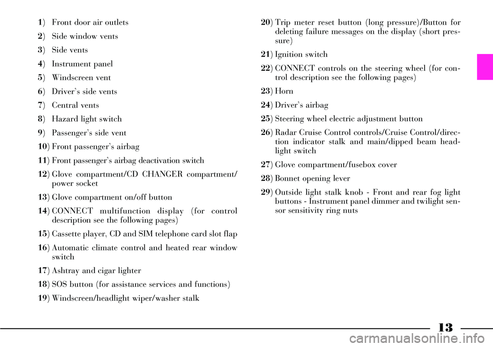
1) Front door air outlets
2) Side window vents
3) Side vents
4) Instrument panel
5) Windscreen vent
6) Driver’s side vents
7) Central vents
8) Hazard light switch
9) Passenger’s side vent
10) Front passenger’s airbag
11) Front passenger’s airbag deactivation switch
12) Glove compartment/CD CHANGER compartment/
power socket
13) Glove compartment on/off button
14) CONNECT multifunction display (for control
description see the following pages)
15) Cassette player, CD and SIM telephone card slot flap
16) Automatic climate control and heated rear window
switch
17) Ashtray and cigar lighter
18) SOS button (for assistance services and functions)
19) Windscreen/headlight wiper/washer stalk 20) Trip meter reset button (long pressure)/Button for
deleting failure messages on the display (short pres-
sure)
21) Ignition switch
22) CONNECT controls on the steering wheel (for con-
trol description see the following pages)
23) Horn
24) Driver’s airbag
25) Steering wheel electric adjustment button
26) Radar Cruise Control controls/Cruise Control/direc-
tion indicator stalk and main/dipped beam head-
light switch
27) Glove compartment/fusebox cover
28) Bonnet opening lever
29) Outside light stalk knob - Front and rear fog light
buttons - Instrument panel dimmer and twilight sen-
sor sensitivity ring nuts
Page 60 of 386

59
AUTOCLOSE FUNCTION
(AUTOMATIC LOCKING
WITH KEYLESS SYSTEM
RECOGNITION SYSTEM)
On versions equipped with Keyless
System, the “Autoclose” function
can be actuated/deactivated through
the CONNECT settings. This func-
tion makes it possible to automati-
cally lock the boot and doors when
the CID device is taken away from
the car.
When leaving the car, if one or
more doors are not closed correctly,
the car will remain open and a fur-
ther beep will sound to indicate that
the locks have not been locked.
The “Autoclose” functions actuates
neither the alarm system nor the
door deadlock device (refer to the
contents of the relevant paragraph).
In any case, these functions can be
actuated by means of the remote
control.LOCK RELEASE IN CASE OF
ACCIDENT
In case of collision with actuation
of the inertia switch, the door locks
are automatically released to allows
rescuers to get access to the passen-
ger compartment.In any case, door open-
ing from the outside
depends on the door con-
ditions after the collision:
deformed doors cannot very often
be opened even if the lock is
released. In such a case, try to
open the other doors.
INITIALISING THE DOOR
LOCKING CONTROL UNIT
Whenever the battery is electrically
connected again or it is reloaded
after being completely flat or after
replacing one of the protection fuses,
to restore the correct operation of
the door locking, of air conditioning
and of ESP system, it is necessary to
perform the initialisation operations
contained in the paragraph “If bat-
tery is to be disconnected” in the
chapter “In an emergency”. The external mechanical
connections are active
only when the doors are
unlocked.
In the event that the driver has
actuated central locking from the
inside and, after a collision, the
inertia switch has not actuated
the automatic door unlocking
function due to the loss of or
damage to the battery, access to
the passenger compartment will
not be possible from the outside.
Page 139 of 386

138
Direction indicators
Warning light/symbol
k
l
m
n
Message
INDICATOR LIGHT FAULT
FRONT LEFT
GO TO DEALER
INDICATOR LIGHT FAULT
FRONT RIGHT
GO TO DEALER
INDICATOR LIGHT FAULT
REAR LEFT
GO TO DEALER
INDICATOR LIGHT FAULT
REAR RIGHT
GO TO DEALERMeaning of the message
Front left-hand direction
indicator doesn’t turn on
Front right-hand direction indica-
tor doesn’t turn on
Rear left-hand direction indicator
doesn’t turn on
Rear right-hand direction indica-
tor doesn’t turn onAction
Contact a Lancia
Dealership
Contact a Lancia
Dealership
Contact a Lancia
Dealership
Contact a Lancia
Dealership
Brake lights
Warning light/symbol
o
p
q
T
Message
BRAKE LIGHT FAULT
LEFT GO TO DEALER
BRAKE LIGHT FAULT
RIGHT GO TO DEALER
BRAKE LIGHT FAULT
LEFT AND RIGHT
GO TO DEALER
BRAKE LIGHT
FUSE FAULT
GO TO DEALERMeaning of the message
Left-hand brake light doesn’t
turn on
Right-hand brake light doesn’t
turn on
Brake lights do not turn on
Brake lights do not turn on
since fuse is blownAction
Contact a Lancia
Dealership
Contact a Lancia
Dealership
Contact a Lancia
Dealership
Contact a Lancia
Dealership
Page 146 of 386

AIR VENTS
The car is fitted with three air
vents set on the dashboard: two
vents A(fig. 118) on driver side and
one B (fig. 119) on passenger side,
sending air in the passenger com-
partment in a “diffused” mode.
This particular function conveys air
at low speed, about half of the usual
flow, through additional vents.
Moreover, it reduces the air impact
on the passengers and the noise due
to the air coming out of the vents,
thus improving the passengers' com-
fort.IMPORTANTWhen the outside
temperature is very high (over 30°C),
to reach the selected temperature as
soon as possible, it is suggested to op-
erate air vents only after the system
has reached steady working condi-
tions.
IMPORTANTOn versions equipped
with solar cell operated sunroof
(where provided), to check operation
at first speed of climate control sys-
tem fan when the car is parked, dis-
engage air vents and set air distribu-
tion from central dashboard vents
only before leaving the car.
fig. 119
L0A0060b
fig. 120
L0A0059b
fig. 118
L0A0061b
145
Air vents (open) are actually used
only when the control for directing
air flow on the instrument panel is
operated.
Air vents are opened by rotating
the dashboard central vent knobs
beyond the upper stop limit (fig.
120):
– control Afor air vents on driver
side
– control Bfor air vent on passen-
ger side.
At the stop limit of these controls
there is a button which, if pressed,
sends a signal to the climate system
control unit.
Page 148 of 386

147
IMPORTANTDuring air distribu-
tion automatic management, all the
air distribution button leds are off.
User can select manually any distri-
bution, and only in this case, the
concerned button led will be lit.
The manual settings have priority
over the automatic settings until the
user returns the system to automatic
control.
Manual setting of a function does
not compromise automatic control
of the other functions.
The amount of air let into the pas-
senger compartment does not
depend on the car speed. It is in fact
adjusted by an electronically con-
trolled fan.
The temperature of the air let into
the passenger compartment is
always controlled automatically
(unless the system is off), according
to the temperatures set on the dri-
ver’s and front/rear passenger’s dis-
plays.The following parameters and
functions can be adjusted manually:
– air temperature on driver/pas-
senger side (front/rear);
– fan speed (continuous variation);
– air distribution in seven positions
(driver/passengers);
– diffused air distribution;
– compressor activation;
– priority of one-zone/two-zone
distribution (front/back);
– rapid defrosting/demisting func-
tion;
– air recirculation;
– automatic/manual system con-
trol;
– heated rear window;
– system off;
– activation of back control panel.
The defrosting/demisting function
includes a set of operations enabling
to defrost/demist rapidly both the
windscreen and the heated rear win-
dow.At each turning off, the system
after storing control and function
conditions, sets up the open recircu-
lation, thus creating the necessary
conditions for operation at first
speed of climate control system fan
at parking, fed by solar cell operated
sunroof (where provided).
IMPORTANTBest operation of
climate control system fan at park-
ing, fed by solar cell operated sun-
roof (where provided), is obtained
by closing completely the windows
and sunroof. Furthermore, to check
operation at first speed of climate
control system fan when the car is
parked, disengage air vents and set
air distribution from central dash-
board vents only before leaving the
car.
When turning on, the system
restores the conditions memorized
before turning off, except for the
rapid defrosting/demisting function
which is reset.
Page 149 of 386

148
FRONT CONTROL PANEL (fig. 121)
fig. 121L0A0054b
INITIALISING THE AIR
CONDITIONING CONTROL UNIT
Whenever the battery is electrically
connected again or it is reloaded
after being completely flat or after
replacing one of the protection fuses,
to restore the correct operation of
the air conditioning, of the door
locking and of the ESP system. It is
necessary to perform the initialisa-
tion operations contained in the
paragraph “If battery is to be dis-
connected” in the chapter “In an
emergency”.
Page 194 of 386

193
The following table summarizes warning light indications according to the different operating conditions.
Operating or failure conditions
Engine start up (key turned to MAR)
Driving in
normal
conditions
Driving inconditions which
might lead to
slipping
ASR fault
ESP fault
System condition
Warning light check
ASR on
ESP on
ASR off
ESP on
ASR active
ESP active
ASR off
ESP active
ASR and ESP off
ASR on
ESP off ASR on
ASR off
manually
ASR on
ASR off
manuallyASR button warning light
On for about 3 seconds
Off
On
Off
On
On
OffESP warning light on
instrument panel
On for about 4 seconds
Off
Off
Flashing
Flashing
On
On
INITIALISING THE ESP SYSTEM CONTROL UNIT
Whenever the battery is electrically connected again or it is reloaded after being completely flat or after replacing one of
the protection fuses, to restore the correct operation of the ESP system, of the door locking, and of the air conditioning, it
is necessary to perform the initialisation operations contained in the paragraph “If battery is to be disconnected” in the chap-
ter “In an emergency”.
Page 225 of 386

224
After battery disconnec-
tion or fuse interruption,
the anti-trap system must
be initialized again as follows:
1) turn selector A clockwise and
fully to its stop, to position 3 cor-
responding to maximum pivoting
(fig. 184)
2) keep selector A depressed
until the sunroof jolts along to the
maximum pivoting position
3) release the selector after the
sunroof has stopped for at least 2
seconds
4) press, within 5 seconds, the
selector again and keep it
depressed
5) the sunroof will start moving
within 5 further seconds and will
perform a complete opening and
closing cycle, after which it will
stop in the closed position
6) release the selector after the
sunroof has stopped for at least 2
seconds.The system is thus initialized
and resumes its normal opera-
tion. If this does not occur, con-
tact your Lancia Dealership.
If the operation is interrupted
before it is completed, repeat the
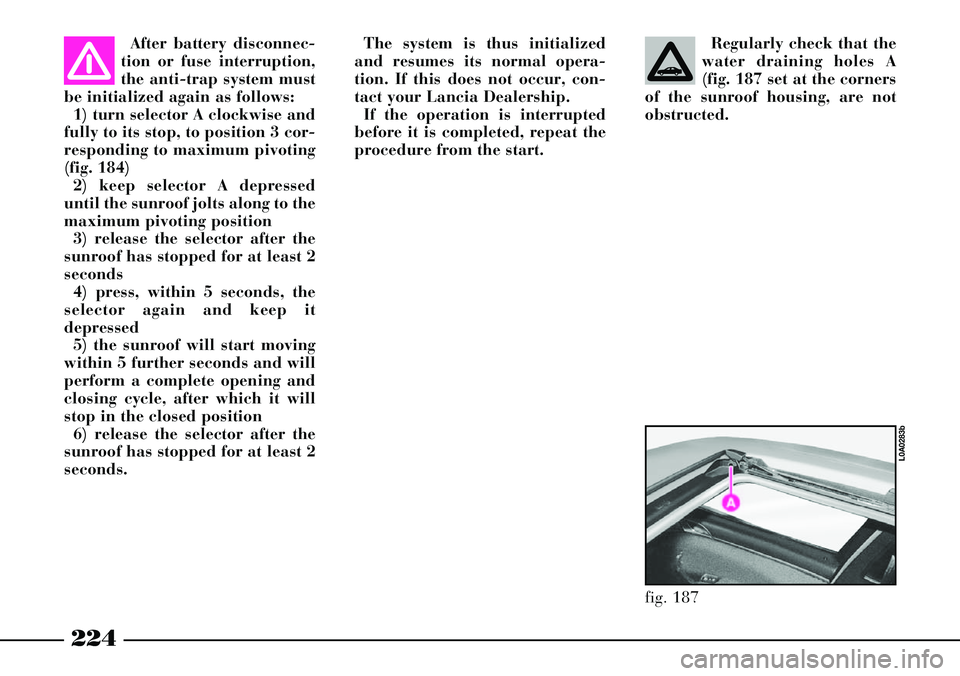
procedure from the start.Regularly check that the
water draining holes A
(fig. 187 set at the corners
of the sunroof housing, are not
obstructed.
fig. 187
L0A0283b
Page 228 of 386

227
BOOT
The boot can be opened both from
the outside and the inside of the car.
IMPORTANT Faulty closing of the
boot is signalled by the lighting of
the relevant symbol on the multi-
function display, together with mes-
sage “BOOT OPEN”With the battery flat, or
after the interruption of
one of the protection
fuses, or if you want to disconnect
a loaded battery (e.g. for a car
stop period), before opening the
luggage compartment bonnet
carefully read and comply with
the instructions contained in the
paragraph “If battery is to be dis-
connected” in the chapter “In an
emergency”.
OPENING FROM THE INSIDE
Boot tailgate is opened electrically.
It can be opened only when the igni-
tion key is at MARand the car is
stopped, or for 3 minutes after turn-
ing the key to STOPwithout open-
ing or closing a door.
To open the boot, press button A
(fig. 192), placed on the central con-
sole, as follows:
– a short pressure of the button will
release the boot lock– a prolonged pressure of the but-
ton will release the lock and open
the boot.
Boot lifting is facilitated by the
action of gas dampers.
The dampers are cali-
brated so as to ensure
correct lifting of the boot
tailgate with the weights estab-
lished by the manufacturer.
Addition of extra equipment (e.g.
spoiler, etc.) can adversely affect
operation and safety of use.
fig. 192
L0A0167b
Page 283 of 386

282
GENERAL INSTRUCTIONS
– When a light is not working,
check that it has not fused before
changing the bulb.
– For the location of the fuses, refer
to “If a fuse blows” in this chapter.
– Before replacing a bulb that does
not work, check that the contacts are
not oxidised.
– Burnt-out bulbs must be replaced
with ones of the same type and
power.
– Always check the slant of the
headlight beam after changing a
bulb for safety reasons.TYPES OF BULBS
Different types of bulbs are
installed in the car (fig. 22):
A - All glass bulbs
Snapped into position. Pull to
remove.
B - Bayonet connection bulbs
Remove from the bulb holder by
pressing the bulb and rotating it
anticlockwise.
C - Cylindrical bulbs
Remove by pulling away from ter-
minals.
D - E Halogen bulbs
To remove the bulb, release the
clip holding the bulb in place.
L0A0105b
fig. 22