set clock Lancia Thesis 2007 Owner handbook (in English)
[x] Cancel search | Manufacturer: LANCIA, Model Year: 2007, Model line: Thesis, Model: Lancia Thesis 2007Pages: 386, PDF Size: 8.69 MB
Page 35 of 386
34
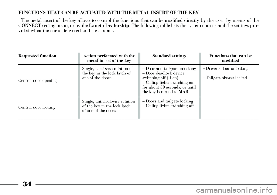
Requested function
Central door opening
Central door locking
Action performed with the
metal insert of the key
Single, clockwise rotation of
the key in the lock latch of
one of the doors
Single, anticlockwise rotation
of the key in the lock latch
of one of the doorsStandard settings
– Door and tailgate unlocking
– Door deadlock device
switching off (if on)
– Ceiling lights switching on
for about 30 seconds, or until
the key is turned to MAR
– Doors and tailgate locking
– Ceiling lights switching offFunctions that can be
modified
– Driver’s door unlocking
– Tailgate always locked
FUNCTIONS THAT CAN BE ACTUATED WITH THE METAL INSERT OF THE KEY
The metal insert of the key allows to control the functions that can be modified directly by the user, by means of the
CONNECT setting menu, or by the Lancia Dealership. The following table lists the system options and the settings pro-
vided when the car is delivered to the customer.
Page 111 of 386
110
KILOMETRE COUNTER (AND
TRIP METER) AND AUTOMATIC
GEARBOX
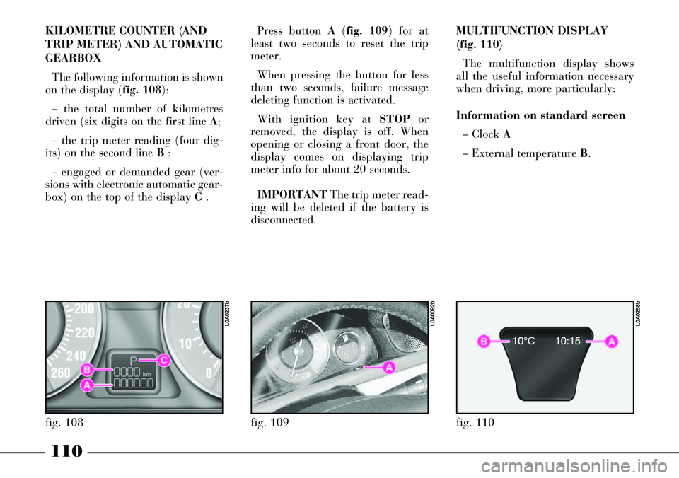
The following information is shown
on the display (fig. 108):
– the total number of kilometres
driven (six digits on the first line A;
– the trip meter reading (four dig-
its) on the second line B ;
– engaged or demanded gear (ver-
sions with electronic automatic gear-
box) on the top of the display C .Press button A(fig. 109) for at
least two seconds to reset the trip
meter.
When pressing the button for less
than two seconds, failure message
deleting function is activated.
With ignition key at STOPor
removed, the display is off. When
opening or closing a front door, the
display comes on displaying trip
meter info for about 20 seconds.
IMPORTANTThe trip meter read-
ing will be deleted if the battery is
disconnected.
fig. 108
L0A0237b
fig. 109
L0A0092b
MULTIFUNCTION DISPLAY
(fig. 110)
The multifunction display shows
all the useful information necessary
when driving, more particularly:
Information on standard screen
– Clock A
– External temperature B.
fig. 110
L0A0258b
Page 225 of 386
224
After battery disconnec-
tion or fuse interruption,
the anti-trap system must
be initialized again as follows:
1) turn selector A clockwise and
fully to its stop, to position 3 cor-
responding to maximum pivoting
(fig. 184)
2) keep selector A depressed
until the sunroof jolts along to the
maximum pivoting position
3) release the selector after the
sunroof has stopped for at least 2
seconds
4) press, within 5 seconds, the
selector again and keep it
depressed
5) the sunroof will start moving
within 5 further seconds and will
perform a complete opening and
closing cycle, after which it will
stop in the closed position
6) release the selector after the
sunroof has stopped for at least 2
seconds.The system is thus initialized
and resumes its normal opera-
tion. If this does not occur, con-
tact your Lancia Dealership.
If the operation is interrupted
before it is completed, repeat the
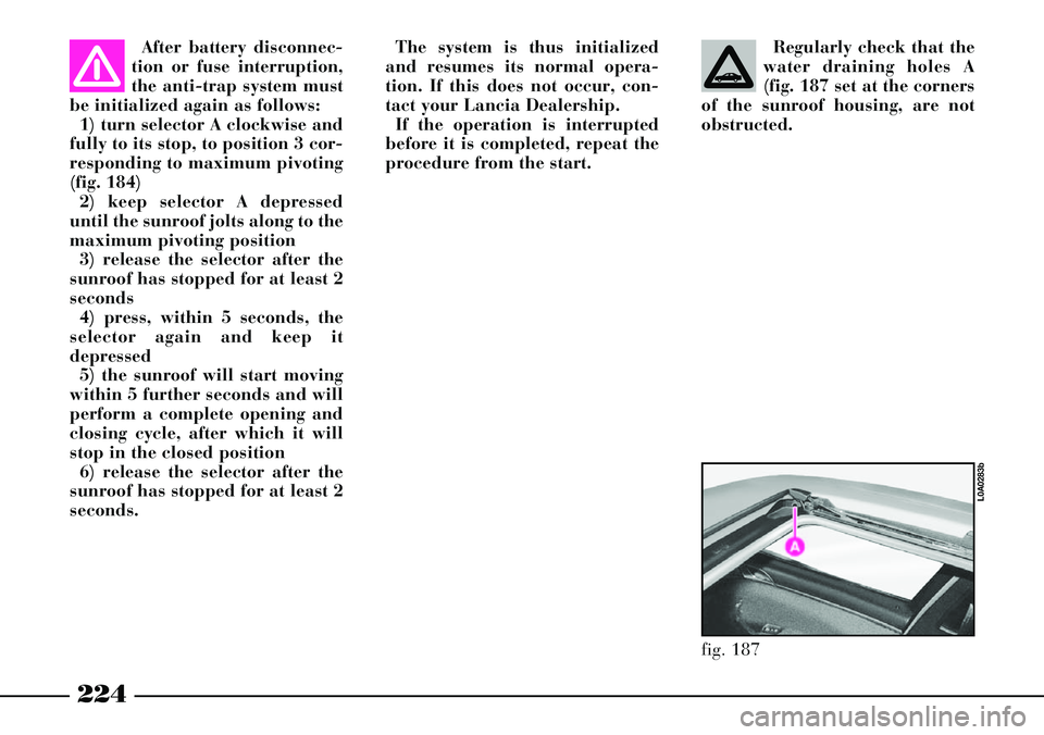
procedure from the start.Regularly check that the
water draining holes A
(fig. 187 set at the corners
of the sunroof housing, are not
obstructed.
fig. 187
L0A0283b
Page 227 of 386
226
SOLAR CELLS
The upper part of the sunroof
incorporates 21 solar cells that pro-
duce a maximum power of 24 W to
feed the climate control system fan,
when the car is parked with the sun-
roof closed or in pivoting position.
Fan actuation is automatic and air
distribution corresponds to the latest
setting made before switching the
car off.
This function is useful especially on
summer days, since it greatly
reduces the temperature inside the
passenger compartment as well as
the duration of the cooling cycle
after car start-up, thus avoiding the
accumulation of warm air in the air-
conditioning unit lines.
In winter, the ventilation function
reduces dampness inside the passen-
ger compartment.EMERGENCY MANOEUVRE
In case the electric actuation device
fails to operate, the sunroof can be
actuated manually, proceeding as
follows:
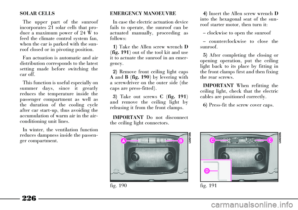
1)Take the Allen screw wrench D
(fig. 191) out of the tool kit and use
it to actuate the sunroof in an emer-
gency.
2)Remove front ceiling light caps
Aand B(fig. 190) by levering with
a screwdriver on the outer side (the
caps are press-fitted).
3)Take out screws C(fig. 191)
and remove the ceiling light by
releasing it from the front clamps.
IMPORTANTDo not disconnect
the ceiling light connectors.4)Insert the Allen screw wrench D
into the hexagonal seat of the sun-
roof starter motor, then turn it:
– clockwise to open the sunroof
– counterclockwise to close the
sunroof.
5)After completing the closing or
opening operation, put the ceiling
light back to its place by fitting in
the front clamps first and then fixing
the rear screws.
IMPORTANTWhen refitting the
ceiling light, check that the electric
cables are positioned correctly.
6)Press-fit the screw cover caps.
fig. 190
L0A0129b
fig. 191
L0A0329b
Page 304 of 386
303
DISCONNECTING THE
UNLOADED BATTERY
Should the discharged battery be
disconnected (to have it charged
again or to replace it) perform the fol-
lowing operations in the given order:
1) To open the boot from the out-
side, fully turn the key anticlockwise
in the lock (fig. 81), and at the same
time slightly press the lower edge of
the number plate holder to reduce op-
eration effort.
2) Remove the cover and disconnect
the battery terminals.
3) Fully charge the battery again or
replace it.4) Connect battery terminals and re-
assemble cover.
5) Depress push button A(fig. 81)
to restore normal lock operation.
6) Close boot normally without
slamming it down: lock electric servo
control will fully lock it.
7) Perform the initialisation proce-
dure of the door lock, air conditioner
and ESP system control units, here-
after described.INITIALISING THE CONTROL
UNITS OF THE DOOR LOCKS,
AIR CONDITIONER AND ESP
SYSTEM
Whenever the battery is connected
electrically or protection fuses are re-
placed, to restore correct door locking,
air conditioning and ESP system, per-
form the following operations (after
connection is performed or after re-
placing one of the fuses):
1) Enter key into the lock of one of
the front doors and perform a door
centralised opening/closing cycle.
2) Start the engine and turn on the
compressor of the conditioner, setting
a lower temperature value than that
of the environment and check
whether the led on the disconnection
push button of the conditioner com-
pressor òis lit.
3) Start running the car and drive it
for a few meters in a straight line (ac-
celerating), until the ESP warning
light is off
á. It is not possible to close
the boot when battery is
discharged or discon-
nected for the purpose of being re-
placed/ charged again: do not try
to close the boot by slamming it
down. The boot remains anyhow
hooked on and it must be re-
opened by turning the key in the
lock.