Number plate Lancia Thesis 2009 Owner handbook (in English)
[x] Cancel search | Manufacturer: LANCIA, Model Year: 2009, Model line: Thesis, Model: Lancia Thesis 2009Pages: 386, PDF Size: 4.96 MB
Page 94 of 386

IMPORTANTIf the ¬warning
light does not turn on when turning
the ignition key to MARor if it stays
on when travelling, (together with
message on display) this could indi-
cate a failure in safety retaining sys-
tems; under this condition air bags
or pretensioners could not trigger in
the event of collision or, in a restrict-
ed number of cases, they could trig-
ger accidentally. Stop the car and
contactLancia Dealershipto have
the system checked immediately.
The air bag system has a validity
of 14 years as concerns the py-
rotechnic charge and 10 years as
concerns the coil contact (see the
plate on the front let door). As these
dates approach, contact Lancia
Dealership to have them replaced.
IMPORTANTAfter an accident
which triggered the airbags, go to a
Lancia Dealershipto have the
entire safety system, the electronic
control unit, the seat belts and the
pretensioners replaced and to have
the electrical system checked. Never lean head, arms
and elbows out of the
window.Operation of the front bags is not
disabled by the passenger’s front
airbag and rear side bag deactiva-
tion switch.
IMPORTANTIn the event of side
crash, you can obtain the best pro-
tection by the system keeping a cor-
rect position on the seat, allowing
thus a correct window bag unfold-
ing.IMPORTANTThe front airbags
and/or front and rear side bags can
be triggered if the car is involved in
hard impacts or collisions in the area
of the underbody, such as for exam-
ple violent impacts against steps,
kerbs or projecting objects fixed to
the ground or if the car falls into
large pot-holes or dips in the road
surface.
IMPORTANTWhen the airbag is
fired it emits a small amount of
powder and smoke. This is not
harmful and does not indicate the
beginning of a fire. Furthermore the
surface of the inflated bag and the
passenger compartment may be cov-
ered with powder residues. This
powder may irritate skin and eyes.
In the event of exposure, wash with
mild soap and water.
93
Never rest head, arms
and elbows on the door,
on the windows and in the
window bag area to prevent pos-
sible injuries during the inflation
phase.
Page 98 of 386

97
LIGHT SWITCH
AND STEERING
COLUMN STALKS
The devices and services controlled
by light switch and steering column
stalks can only be activated with the
ignition key at MAR, excluding the
parking lights that are switched on
only with key at STOPor removed.
Outside lights can be switched on
manually or automatically accord-
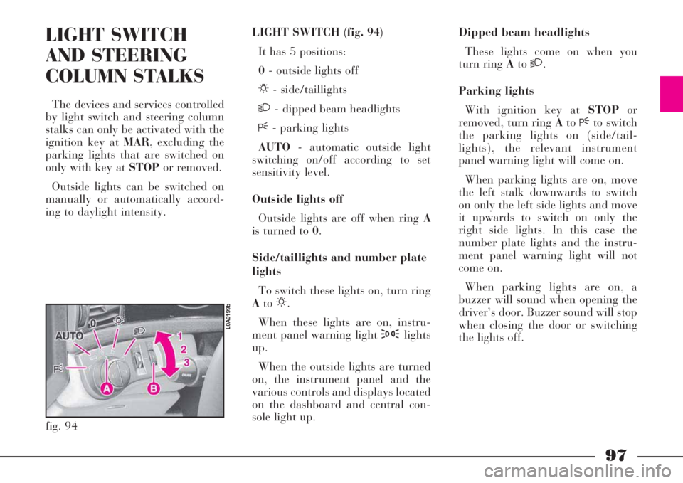
ing to daylight intensity.LIGHT SWITCH (fig. 94)
It has 5 positions:
0- outside lights off
6- side/taillights
2- dipped beam headlights
F- parking lights
AUTO- automatic outside light
switching on/off according to set
sensitivity level.
Outside lights off
Outside lights are off when ring A
is turned to 0.
Side/taillights and number plate
lights
To switch these lights on, turn ring
Ato6.
When these lights are on, instru-
ment panel warning light 3lights
up.
When the outside lights are turned
on, the instrument panel and the
various controls and displays located
on the dashboard and central con-
sole light up.Dipped beam headlights
These lights come on when you
turn ring Ato2.
Parking lights
With ignition key at STOPor
removed, turn ring AtoFto switch
the parking lights on (side/tail-
lights), the relevant instrument
panel warning light will come on.
When parking lights are on, move
the left stalk downwards to switch
on only the left side lights and move
it upwards to switch on only the
right side lights. In this case the
number plate lights and the instru-
ment panel warning light will not
come on.
When parking lights are on, a
buzzer will sound when opening the
driver’s door. Buzzer sound will stop
when closing the door or switching
the lights off.
fig. 94
L0A0199b
Page 99 of 386

98
Automatic switching on/off
When ring Ais turned to AUTO
and the ignition key is at MAR,
side/taillights, number plate lights
and dipped beam headlights will
turn on/off automatically according
to daylight intensity.
The twilight sensor sensitivity of
the automatic light on/off system
can be set, also when travelling,
through the 3-position ring B:
1- low sensitivity
2- medium sensitivity
3- high sensitivity.
IMPORTANTMain beam head-
lights can only be switched on man-
ually by moving the left stalk for-
wards.If main beam headlights
are on (left stalk for-
wards), they will turn on
automatically each time the twi-
light sensor makes the outside
lights switch on automatically. It
is therefore recommended to turn
off the main beam headlights (if
on), moving backwards the left
stalk, each time the sensor
switches off the outside lights.
Twilight sensor is not
able to detect the fog
presence, it is therefore
necessary to switch on the lights
manually, including the front and
rear fog lights.The driver is responsible
for the use of the lights
according to the light
intensity and traffic regulations
of the country where the car is
being driven. Automatic switch-
ing on/off must be considered
just as an help for the driver
since he/she must always switch
on/off the lights manually as nec-
essary.With automatic switching on acti-
vated and switching off control
given by the sensor, main beam
headlights go off followed after
about 10 seconds, by the side/tail-
lights.IMPORTANTWhen switching on
the headlights automatically, it is
possible to switch on the front and
rear fog lights. When headlights are
automatically switched off, the front
and rear fog lights (if previously
activated) will be switched off as
well. At the following automatic
switching-on, only the front fog
lights will switch on, whereas the
rear fog lights, if required, will have
to be switched on manually.
Page 140 of 386

Action
Before reactivating
the switch read care-
fully through the
instructions given in the rele-
vant paragraph
139
Rear fog lights
Warning light/symbol
o
p
q
Message
REAR FOG LIGHT
FAULT LEFT
GO TO DEALER
REAR FOG LIGHT
FAULT RIGHT
GO TO DEALER
REAR FOG LIGHT FAULT
LEFT AND RIGHT
GO TO DEALERMeaning of the message
Left-hand rear fog
light doesn’t turn on
Right-hand rear fog
light doesn’t turn on
Rear fog lights
don’t turn onAction
Contact a
Lancia Dealership
Contact a
Lancia Dealership
Contact a
Lancia Dealership
Number plate light
Warning light/symbol
r
Message
NUMBER PLATE LIGHT
FAULT GO TO DEALERMeaning of the message
One or both number plate lights
don’t turn onAction
Contact a Lancia
Dealership
Inertia switch (Fuel cut-off switch)
Warning light/symbol
s
Message
INERTIA
SWITCH ONMeaning of the message
Inertia switch has cut in
after an impact/collision
Page 229 of 386

228
OPENING FROM THE OUTSIDE
WITH THE KEY (fig. 193)
The boot lock is electrified: press
buttonAon the tailgate to open it.
In an emergency (battery run down
or electrical system failure), the tail-
gate can be opened by fully turning
counterclockwise the key in the lock
and exerting at the same time a
slight pressure on the lower edge of
the number plate holder to reduce
the opening effort.
IMPORTANTIf the boot was
opened using the key, at closing the
automatic function will be deacti-
vated. To restore the automatic
function press button A.OPENING BY MEANS OF THE
REMOTE CONTROL
The tailgate can be opened from
the outside by pressing button A
(fig. 194) on the remote control,
even when the electronic alarm is on.
When the electronic alarm is on,
boot opening is accompanied by
double flashing of direction indica-
tors; boot closing is accompanied by
one flashing.
IMPORTANTIf the boot is opened
with the key when the electronic
alarm is on, the latter will not be
deactivated.If the electronic alarm is on, both
the volumetric protection and the
boot control sensor will be switched
off, and the system will emit (except
for versions of certain markets) two
beeps.
fig. 193
L0A06022b
fig. 194
L0A0179b
Page 284 of 386

283
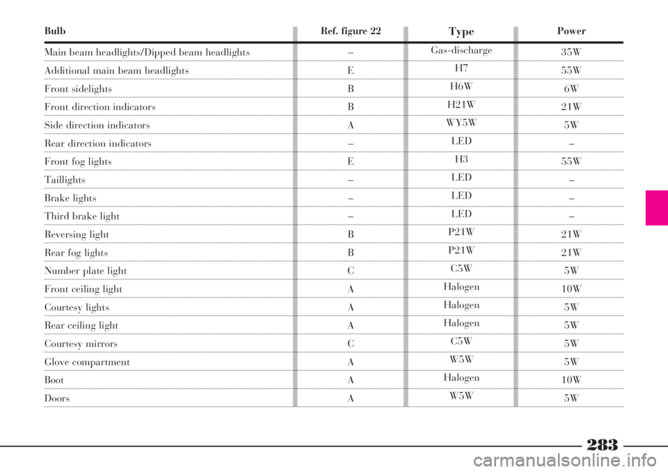
Bulb
Main beam headlights/Dipped beam headlights
Additional main beam headlights
Front sidelights
Front direction indicators
Side direction indicators
Rear direction indicators
Front fog lights
Taillights
Brake lights
Third brake light
Reversing light
Rear fog lights
Number plate light
Front ceiling light
Courtesy lights
Rear ceiling light
Courtesy mirrors
Glove compartment
Boot
Doors
Power
35W
55W
6W
21W
5W
–
55W
–
–
–
21W
21W
5W
10W
5W
5W
5W
5W
10W
5W
Type
Gas-discharge
H7
H6W
H21W
WY5W
LED
H3
LED
LED
LED
P21W
P21W
C5W
Halogen
Halogen
Halogen
C5W
W5W
Halogen
W5W
Ref. figure 22
–
E
B
B
A
–
E
–
–
–
B
B
C
A
A
A
C
A
A
A
Page 288 of 386

287
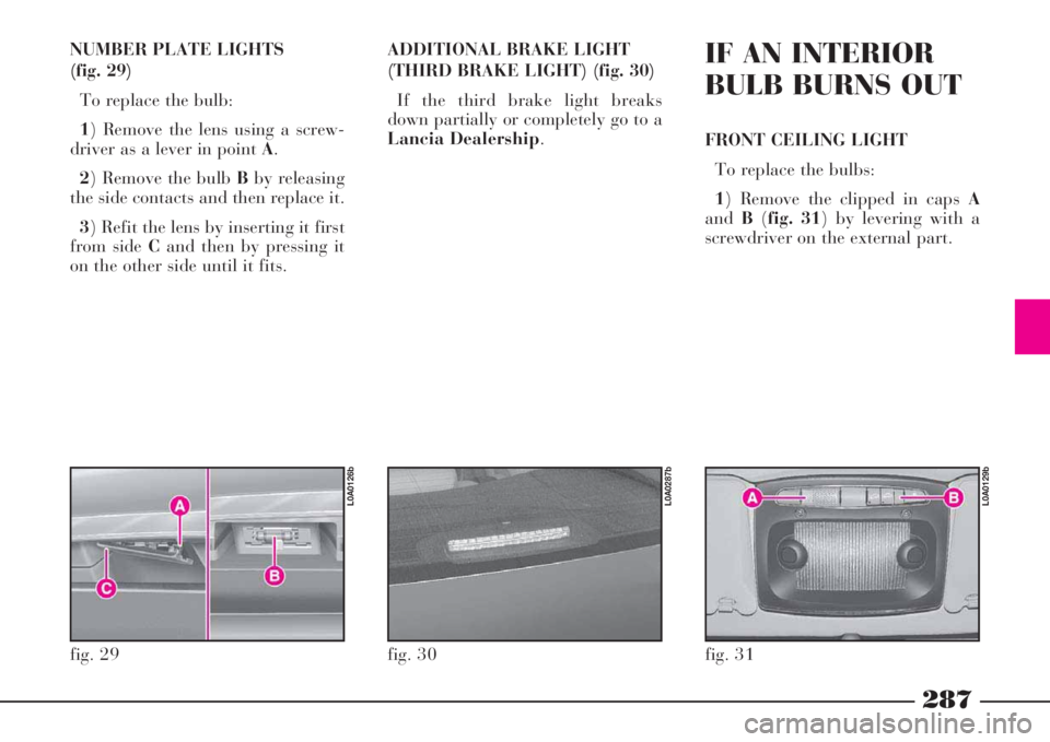
NUMBER PLATE LIGHTS
(fig. 29)
To replace the bulb:
1) Remove the lens using a screw-
driver as a lever in point A.
2) Remove the bulb Bby releasing
the side contacts and then replace it.
3) Refit the lens by inserting it first
from side Cand then by pressing it
on the other side until it fits.ADDITIONAL BRAKE LIGHT
(THIRD BRAKE LIGHT) (fig. 30)
If the third brake light breaks
down partially or completely go to a
Lancia Dealership.IF AN INTERIOR
BULB BURNS OUT
FRONT CEILING LIGHT
To replace the bulbs:
1) Remove the clipped in caps A
andB(fig. 31) by levering with a
screwdriver on the external part.
fig. 29
L0A0126b
fig. 30
L0A0287b
fig. 31
L0A0129b
Page 303 of 386

302
IF BATTERY IS TO BE DISCONNECTED
Battery is housed on the left side of
the luggage compartment, protected
by cover B(fig. 79). To remove cover
unscrew knob A.
DISCONNECTING THE
LOADED BATTERY
Should the charged battery be dis-
connected (e.g. during a car inactivity
time) perform these operations in the
given order:
1) Depress the push button on the
central console or on the remote con-
trol to open the boot. 2) Depress manually the inside hook
A(fig. 80) of the boot lock, and push
it back completely until the recall
electric travel is activated.
3) Remove the cover and disconnect
battery terminals.
4) Fully turn anti-clockwise the key
into the outside bonnet lock to pull
out the locking hook (fig. 81).
5) If necessary, it is now possible to
fully close the boot, leaving the bat-
tery disconnected.
6) When the battery it to be con-
nected again, to open the bonnet, fully
fig. 79
L0A0030b
fig. 80
L0A0332b
turn the key anticlockwise in the lock,
and at the same time slightly press the
lower edge of the number plate holder
to reduce operation effort (fig. 81).
7) Connect battery terminals and as-
semble the cover again.
8) Depress push button A(fig. 81)
to restore normal lock operation.
9) Normally close the boot without
slamming it down; the lock electric
servo control will fully lock it.
10) Perform the initialisation of the
door lock, air conditioner and ESP
system control units, described below.
fig. 81
L0A6022b
Page 304 of 386

303
DISCONNECTING THE
UNLOADED BATTERY
Should the discharged battery be
disconnected (to have it charged
again or to replace it) perform the fol-
lowing operations in the given order:
1) To open the boot from the out-
side, fully turn the key anticlockwise
in the lock (fig. 81), and at the same
time slightly press the lower edge of
the number plate holder to reduce op-
eration effort.
2) Remove the cover and disconnect
the battery terminals.
3) Fully charge the battery again or
replace it.4) Connect battery terminals and re-
assemble cover.
5) Depress push button A(fig. 81)
to restore normal lock operation.
6) Close boot normally without
slamming it down: lock electric servo
control will fully lock it.
7) Perform the initialisation proce-
dure of the door lock, air conditioner
and ESP system control units, here-
after described.INITIALISING THE CONTROL
UNITS OF THE DOOR LOCKS,
AIR CONDITIONER AND ESP
SYSTEM
Whenever the battery is connected
electrically or protection fuses are re-
placed, to restore correct door locking,
air conditioning and ESP system, per-
form the following operations (after
connection is performed or after re-
placing one of the fuses):
1) Enter key into the lock of one of
the front doors and perform a door
centralised opening/closing cycle.
2) Start the engine and turn on the
compressor of the conditioner, setting
a lower temperature value than that
of the environment and check
whether the led on the disconnection
push button of the conditioner com-
pressoròis lit.
3) Start running the car and drive it
for a few meters in a straight line (ac-
celerating), until the ESP warning
light is off
á. It is not possible to close
the boot when battery is
discharged or discon-
nected for the purpose of being re-
placed/ charged again: do not try
to close the boot by slamming it
down. The boot remains anyhow
hooked on and it must be re-
opened by turning the key in the
lock.
Page 342 of 386

341
IDENTIFICATION
DATA
CHASSIS MARKING (fig. 1)
It is printed on the passenger com-
partment floor in front of the right-
hand front seat and can be reached
by lifting the carpeting and opening
the cover.
Marking includes the following
data:
– car model
– chassis number.ENGINE MARKING
The marking is stamped on the
cylinder block and includes the
model and the chassis number.
fig. 1
L0A0296b
fig. 2
L0A0297b
TECHNICAL SPECIFICATIONS
MODEL PLATE
The plate (fig. 2) is to be found on
the left side of the boot (in the spare
wheel housing) by lifting the boot
cover. The plate bears the following
identification data (fig. 3):
A- Manufacturer’s name
B- Homologation number
C- Car model code
D- Chassis number
E- Maximum vehicle weight fully
loaded