ignition Lancia Ypsilon 2002 Owner handbook (in English)
[x] Cancel search | Manufacturer: LANCIA, Model Year: 2002, Model line: Ypsilon, Model: Lancia Ypsilon 2002Pages: 191, PDF Size: 2.45 MB
Page 38 of 191

35
G
LANCIA CODE
(amber)
In three ways (with ignition
key at MAR):
1.A single flash - indicates that the
key code has been recognised. The en-
gine can be started.
2.A constant light - indicates that the
key code has not been recognised. To
start the engine, follow the emergency
startup procedure described in the “In
an emergency” section.
3.A flashing light - indicates that the
car is not protected by the immo-
biliser system. The engine can be
started however.
¢
ABS (ANTI-LOCKING
SYSTEM) FAILURE
(amber)
When the ABS system is inefficient.
The normal braking system continues
to work but you should have the car
seen to at a LANCIA Dealershipas
soon as you can.
The warning lamp will light up when
you turn the key to MAR, but it
should go out as soon as the engine
starts.
>
The car is fitted with an
electronic brake distribu-
tor (EBD). If warning lights
>andxlight up simultaneously
when the engine is running, this
indicates an EBD fault. This
means that violent braking could
cause early locking of the rear
wheels causing the car to skid.
Drive very carefully to the nearest
LANCIA Dealership to have the
system checked.EOBD SELF-
DIAGNOSTIC SYSTEM
(amber)
In normal conditions, the warning
light will come on when the ignition
key is turned to MARand should go
out as soon as the engine is started.
The initial lighting up shows that the
warning light is working properly.
If the warning light either stays on or
comes on while travelling:
1.Fixed light - warning of a fuel
feed/ignition system failure which
If only warning light>
switches on when the en-
gine is running, this usu-
ally indicates an ABS fault. In such
cases the braking system is still ef-
ficient, although the anti-locking
device does not function. The EBD
system may also be less efficient.
Go to a LANCIA Dealership imme-
diately, taking care not to brake
suddenly, and have the system
checked.HAZARD LIGHTS
(red) (flashing)
When the hazard lights are
switched on.
r
4C001-067 ING 11-03-2008 11:57 Pagina 35
Page 45 of 191

42
G
RIGHT-HAND STALK
Windscreen wash/wipe (fig. 51)
This feature can only work when the
ignition key is at MAR.
Controls:
0- windscreen wiper off;
1- flick wipe;
2- slow continuous wipe;
3- fast continuous wipe;
4- temporary function: when you
release the stalk it returns to position
0and automatically turns off the
windscreen wiper.
fig. 51
P4C00090
To flash the lights (fig. 49)
Pull the stalk towards the steering
wheel (temporary position).Direction indicators (fig. 50)
Move the stalk as follows to turn on
the direction indicators:
up - for the right indicator;
down - for the left indicator.
Instrument panel indicator light y
flashes.
The direction indicators automati-
cally return to the neutral position
when the car straightens up.
If you want the indicator to flash
briefly, move the stalk up or down
without it clicking into position. When
you let it go it will return to its origi-
nal position.
fig. 48
P4C00087
fig. 49
P4C00088
fig. 50
P4C00089
4C001-067 ING 11-03-2008 11:57 Pagina 42
Page 46 of 191

43
G
When you pull the lever towards the
steering wheel (fig. 52), a jet of liquid
shoots out from the windscreen
washer.Rear window wash/wipe (fig. 53)
This function is only possible when
the ignition key is at MAR.
Controls:
1)turn the control from åto'for
continous wiper operation;
2)when you push the control stalk
forward (temporary position), a jet of
liquid shoots out from the rear win-
dow washer and the rear window
wiper comes into operation. When you
let the lever go again the rear window
washer/ wiper ceases to function.
fig. 52
P4C00091
fig. 53
P4C00092
CONTROLS
HAZARD LIGHTS
These come on when switch A
(fig. 54)is pressed, regardless of the
position of the ignition key.
When these lights are on, the panel
warning light
rflashes.
Press the switch again to turn the
lights off.
fig. 54
P4C00343
4C001-067 ING 11-03-2008 11:57 Pagina 43
Page 51 of 191

48
G
A key C (fig. 67)is attached to the
back of the cover B (fig. 67); insert
this key into D (fig. 68) and turn it to
manually perform the operations de-
scribed previously (opening/closing).
To reach D, remove the press-fitted
cover.
fig. 68
P4C00187
Do not open the roof if
there is snow or ice on it as
you risk damaging it.
SUNROOF
The sunroof is electrically operated.
It will only work if the ignition key
is at MAR.
ButtonA (fig. 65)on the ceiling light
unit controls the opening, closing,
raising and lowering of the roof.
When you release the button, the
roof locks in the position it is in at
that moment.
£Press once to open in the spoiler
position.
Press again to open completely.
¢Press to close.
fig. 65
P4C00101
A sliding sunshade, fitted under the
sunroof, will lessen the effect of the
sun’s rays or the amount of air enter-
ing the car (fig. 66).
If there is an electrical fault in the
sunroof, open the glove compartment.
fig. 66
P4C00102
fig. 67
P4C00103
4C001-067 ING 11-03-2008 11:57 Pagina 48
Page 53 of 191

50
G
Incorrect use of the elec-
tric windows could be
dangerous. Before and
when pressing the switches, always
make sure that passengers are not
liable to injury either directly by
the movement of the windows or
by personal effects being dragged
along or knocked by the windows.
Always remove the ignition key
when getting out of the car to make
sure that the electric windows can-
not be accidentally operated and
constitute a hazard for passengers
remaining in the car.
The door handle on the passenger
side has a button to control that par-
ticular window. IMPORTANTFor versions with
door locking/unlocking remote con-
trol, see the “Lancia CODE system -
Door lock/unlock remote control”
paragraph at the beginning of this
chapter.
IMPORTANTIf one of the doors is
not shut properly or there is a failure
in the system, the central locking fea-
ture will not work and, after some at-
tempts, the device stops working for
around two minutes. In these two min-
utes the doors can be locked or un-
locked manually without the electrical
system coming into play. After the two
minutes, the control unit is ready to
receive commands once more.
If the reason for the malfunction has
been removed, the device will start to
work properly again. If not, it will cut
out once more.ELECTRIC WINDOWS
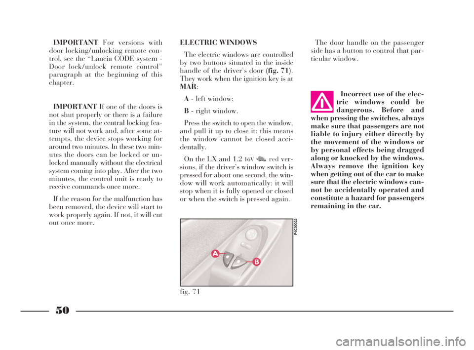
The electric windows are controlled
by two buttons situated in the inside
handle of the driver’s door (fig. 71).
They work when the ignition key is at
MAR:
A- left window;
B- right window.
Press the switch to open the window,
and pull it up to close it: this means
the window cannot be closed acci-
dentally.
On the LX and 1.2
16VM M Nredver-
sions, if the driver’s window switch is
pressed for about one second, the win-
dow will work automatically: it will
stop when it is fully opened or closed
or when the switch is pressed again.
fig. 71
P4C00022
4C001-067 ING 11-03-2008 11:57 Pagina 50
Page 54 of 191

51
G
BOOT
OPENING/CLOSING
THE TAILGATE
To open the boot from the outside,
unlock it with the ignition key A
(fig. 72).
To open it from inside the car, pull
leverA (fig. 73)at the side of the dri-
ver’s seat.
To lift the tailgate, use the grip lo-
cated between the two number plate
lights.When the tailgate is closed, it will
lock automatically, and can only be
reopened by using the key or pulling
leverA (fig. 73)inside the car.
IMPORTANTNever leave the keys
in the boot.
Use the handle situated in the inte-
rior trim of the tailgate A (fig. 74)to
lower it without getting your hands
dirty.
To close the tailgate, lower it and
press in the centre until you hear it
lock.
fig. 72
P4C00021
fig. 73
P4C00015
Do not work boot release
lever when the car is in
motion.
The addition of objects to
the rear parcel shelf or
tailgate (loudspeakers,
spoiler, etc.) may prevent the gas-
filled struts at the sides of the tail-
gate working properly. Items
arranged on the rear window shelf
could be thrown forwards and in-
jure passengers should you brake
sharply.
fig. 74
P4C00037
When using the boot,
make sure the load you are
carrying does not exceed
the permitted weight (see the
“Technical specifications” sec-
tion). Also ensure the items in the
boot are arranged properly to pre-
vent them being thrown forward
and injurying passengers should
you brake sharply.
4C001-067 ING 11-03-2008 11:57 Pagina 51
Page 57 of 191

54
G
To close the bonnet:
1)Hold the bonnet up with one
hand and, with the other, remove rod
A (fig. 82)from recess Cand replace
it in its clip B.
2)Lower the bonnet until it is about
20 cm (8 ins) above the engine com-
partment.
3)Let it fall: the bonnet closes auto-
matically.
Always make sure the
bonnet is closed properly
so it will not open while
travelling.
2)Lift lever B (fig. 81).
3)Lift the bonnet, and release the
support rod A (fig. 82)from its clip B.
4)Place the tip of the support rod in
recessCof the bonnet.
fig. 81
P4C00005
Important. The bonnet
might fall violently if the
support rod is not posi-
tioned properly.
Scarves, ties and loose
garmets can get caught in
moving parts. This can be
extremely dangerous.
fig. 82
P4C00006
If repairs need to be car-
ried out inside the engine
compartment when this is
still hot, be careful not to burn
yourself and keep away from the
electric fan as this may cut in at
any time, even if the key is re-
moved from the ignition switch.
Wait until the engine has cooled.
4C001-067 ING 11-03-2008 11:57 Pagina 54
Page 62 of 191

59
G
Europe and most other countries
world-wide.
In the event of front collisions at low
speed, the restraining action of the
seat belts is sufficient and the airbag
is not inflated.
For impacts against very deformable
or mobile objects (traffic sign poles,
heaps of gravel or snow, parked vehi-
cles), side impacts, wedging under
other vehicles or barriers (e.g. under
a truck or guard rail), the airbag is
not necessary and may even be unde-
sirable.
The fact that the airbag is not trig-
gered in these situations, this does not
signify a malfunction.
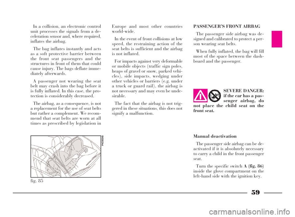
fig. 85
P4C00348
PASSENGER’S FRONT AIRBAG
The passenger side airbag was de-
signed and calibrated to protect a per-
son wearing seat belts.
When fully inflated, the bag will fill
most of the space between the dash-
board and the passenger. In a collision, an electronic control
unit processes the signals from a de-
celeration sensor and, where required,
inflates the airbag.
The bag inflates instantly and acts
as a soft protective barrier between
the front seat passengers and the
structures in front of them that could
cause injury. The bags deflate imme-
diately afterwards.
A passenger not wearing the seat
belt may crash into the bag before it
is fully inflated. In this case, the pro-
tection is considerably decreased.
The airbag, as a consequence, is not
a replacement for the use of seat belts
but rather a complement. We recom-
mend that seat belts are worn at all
times as prescribed by legislation inSEVERE DANGER:
if the car has a pas-
senger airbag, do
not place the child seat on the
front seat.
Manual deactivation
The passenger side airbag can be de-
activated if it is absolutely necessary
to carry a child in the front passenger
seat.
Turn the specific switch A (fig. 86)
inside the glove compartment on the
left-hand side with the ignition key.
4C001-067 ING 11-03-2008 11:57 Pagina 59
Page 64 of 191

61
G
GENERAL WARNINGS
The front and/or side airbags
(where fitted) can be triggered if
the car is subjected to consider-
able crashes or involved in an ac-
cident concerning the underbody
areas, such as a violent impact
against steps, kerbs or projecting
objects fastened to the ground,
falling into large holes or dips in
the road surface.
When the airbag is fired it emits
heat and a small amount of pow-
der. This is not harmful and does
not indicate the beginning of a fire.
Furthermore, the surface of the in-
flated bag and in the passenger
compartment may be covered with
a powdery residues. This powder
may irritate skin and eyes. In the
event of exposure, wash with mild
soap and water.
Go to a LANCIA Dealership as
soon as possible if the warning
light
ûcomes on when travelling
(to signal a fault) to have the prob-
lem repaired. The airbag system is guaranteed
for ten years. Contact a LANCIA
Dealership as the expiry data ap-
proaches.
After an accident which triggered
the airbags, go to a LANCIA Deal-
ership to have the entire safety sys-
tem, the electronic control unit, the
seat belts and the pretensioners re-
placed. The Dealership will also
check the intactness of the electri-
cal system.
Any diagnostic, repair or re-
placement operations concerning
the airbag system must exclusively
be carried out at a LANCIA Deal-
ership.
If you are having the car
scrapped, have the airbag system
deactivated at a LANCIA Dealer-
ship first.
If the car changes hands, the new
owner must be made aware of the
indications given above and be
given this Owner Handbook.The pretensioners (if electroni-
cally controlled), front airbags and
side airbags are activated by the
electronic control unit according
to the type of impact. Conse-
quently, missed activation of one
or more system components does
not indicate a fault in the system.
The instrument panel
warning light ûshould
come on when the ignition
key is turned to MAR and go out
after approximately four seconds.
Immediately contact a LANCIA
Dealership if the warning light ei-
ther does not come on or stays on
or comes on when travelling.
4C001-067 ING 11-03-2008 11:57 Pagina 61
Page 69 of 191

66
G
CELLULAR PHONE
SETUP
If the car has been ordered to in-
clude provision for the fitting of cel-
lular phones, it will have:
– one dual purpose speaker (sound
system and cellular phone) located in
the right-hand door;
– one dual purpose aerial (sound
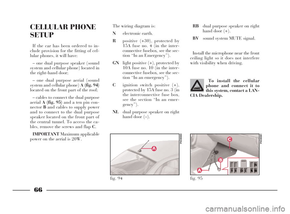
system and cellular phone) A (fig. 94)
located on the front part of the roof;
– cables to connect the dual purpose
aerialA (fig. 95)and a ten pin con-
nectorBand cables to supply power
and to connect to the dual purpose
speaker located on the front part of
the central tunnel. To access the ca-
bles, remove the screws and flap C.
IMPORTANTMaximum applicable
power on the aerial is 20W.The wiring diagram is:
Nelectronic earth.
Rpositive (+30), protected by
15A fuse no. 4 (in the inter-
connective fusebox, see the sec-
tion “In an Emergency”).
GNlight positive (+), protected by
10A fuse no. 10 (in the inter-
connective fusebox, see the sec-
tion “In an emergency”).
Cignition switch positive (+),
protected by 15A fuse no. 3 (in
the interconnective fuse box,
see the section “In an emer-
gency”).
NLdual purpose speaker on right
hand door (–).To install the cellular
phone and connect it to
this system, contact a LAN-
CIA Dealership.
fig. 94
P4C00303
RBdual purpose speaker on right
hand door (+).
BVsound system MUTE signal.
Install the microphone near the front
ceiling light so it does not interfere
with visibility when driving.
fig. 95
P4C00361
4C001-067 ING 11-03-2008 11:57 Pagina 66