light Lancia Ypsilon 2002 Owner handbook (in English)
[x] Cancel search | Manufacturer: LANCIA, Model Year: 2002, Model line: Ypsilon, Model: Lancia Ypsilon 2002Pages: 191, PDF Size: 2.45 MB
Page 47 of 191

44
G
C- To switch the heated rear win-
dow on/off. It will switch on the door
mirrors demisting device at the same
time, if this feature is included.
D- To switch the climate control
system on and off.
FUEL CUT-OFF SWITCH
This is a safety cut-out which comes
into play in the case of an accident
and blocks the fuel supply, thereby
stopping the engine.
After an accident, turn the igni-
tion key to STOP to prevent the
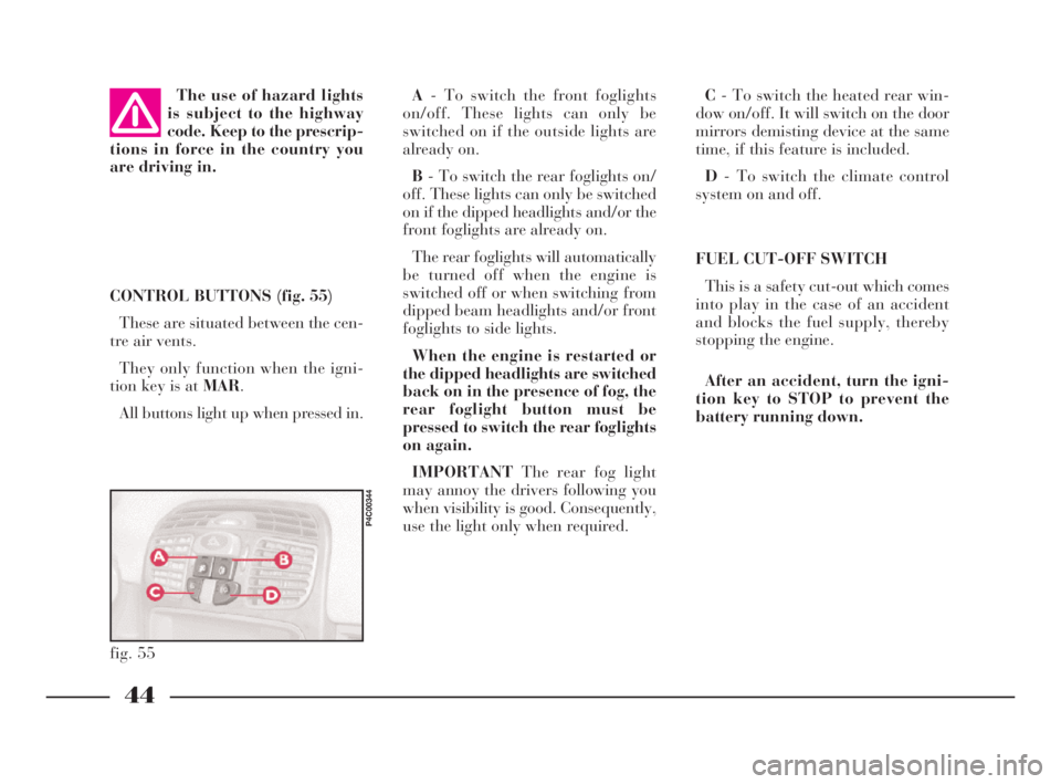
battery running down. CONTROL BUTTONS (fig. 55)
These are situated between the cen-
tre air vents.
They only function when the igni-
tion key is at MAR.
All buttons light up when pressed in. The use of hazard lights
is subject to the highway
code. Keep to the prescrip-
tions in force in the country you
are driving in.
fig. 55
P4C00344
A- To switch the front foglights
on/off. These lights can only be
switched on if the outside lights are
already on.
B- To switch the rear foglights on/
off. These lights can only be switched
on if the dipped headlights and/or the
front foglights are already on.
The rear foglights will automatically
be turned off when the engine is
switched off or when switching from
dipped beam headlights and/or front
foglights to side lights.
When the engine is restarted or
the dipped headlights are switched
back on in the presence of fog, the
rear foglight button must be
pressed to switch the rear foglights
on again.
IMPORTANTThe rear fog light
may annoy the drivers following you
when visibility is good. Consequently,
use the light only when required.
4C001-067 ING 11-03-2008 11:57 Pagina 44
Page 48 of 191

45
G
INTERIOR
EQUIPMENT
GLOVE COMPARTMENT/
ODDMENT TRAY
To open the compartment, pull han-
dleAas shown in (fig. 57).
On the flap there is a special indent
for inserting a pen or pencil.
If you cannot see any fuel leaks and
the car is in a fit state to continue its
journey, press A (fig. 56)to reactivate
the fuel supply system.If, after an accident, you
can smell petrol or see that
the fuel feed system is
leaking, do not reset the switch to
avoid the risk of fire.
fig. 56
P4C00016
fig. 57
P4C00095
Do not travel with the
glove compartment open
as this could cause injury
in the event of an accident.
CEILING LAMP (fig. 58)
The ceiling lamp will automatically
light up when one of the front doors
is opened.
If the doors are closed, the lamp can
be switched on by pressing the side of
the lens.
fig. 58
P4C00096
4C001-067 ING 11-03-2008 11:57 Pagina 45
Page 49 of 191

46
G
sition and the cigar lighter is ready to
use.
The ashtray can be removed.
IMPORTANTMake sure that the
cigar lighter does in fact pop out af-
ter it has been pushed in.
The rear seats have a concealed ash-
tray in the right side panel.
Follow the direction of the arrow to
use and extract the ashtray (fig. 61).
fig. 61
P4C00099
CEILING LAMP (fig. 59)
SwitchesAandBswitch the ceiling
lights on and off.
The following conditions are created
according to the position of these
switches:
–with switch A in the centre po-
sition, light Cin the ceiling lamp will
come on when the doors are opened;
–with switch A moved to the left,
lightCin the ceiling lamp is off and
will not light up if the doors are
opened;
–with switch A moved to the
right, light Cin the ceiling lamp will
light up regardless of whether the
doors are open or not.SwitchBwill switch the map-read-
ing light Don/off (spot light).
IMPORTANTBefore getting out of
the car, make sure that switch Ais in
the centre position; the ceiling light will
then go out when the doors are closed
and you will not drain the battery.
ASHTRAY AND CIGAR LIGHTER
How to use them:
1)Open flap A (fig. 60)in the di-
rection of the arrow to reach the cigar
lighter and the ashtray.
2)Press button B: after around fif-
teen seconds it returns to its initial po-
fig. 60
P4C00215
fig. 59
P4C00097
4C001-067 ING 11-03-2008 11:57 Pagina 46
Page 50 of 191

47
G
The symbol indicating the presence
of a front passenger airbag is printed
on the under-side of the sun visor
(visible when the visor is pushed up)
(fig. 63).
SUN VISORS (fig. 62)
These are positioned to the sides of
the driving mirror. They can swing up
or down or be pivoted sideways.
On the back of the driver’s sun vi-
sor, there is a document pocket with
a vanity mirror and protective flap.
The inside of the passenger’s sun vi-
sor is only fitted with a vanity mirror.The cigar lighter gets very
hot. Be careful how you
handle it and make sure it
is not used by children: danger of
fire and/or burns.Do not use the ashtray as
a waste-paper basket: the
paper could set fire if it
comes into contact with a smoul-
dering cigarette stub.
fig. 62
P4C00100
REAR SIDE WINDOWS
These windows are hinged:
1)Move the lever as shown in
(fig. 64).
2)Push the lever outwards until the
window opens completely.
3)Push the lever back until you hear
it lock into place.
To close these windows, reverse the
above procedure until you hear the
lever click back into position.
fig. 64
P4C00024
fig. 63
P4C00424
4C001-067 ING 11-03-2008 11:57 Pagina 47
Page 51 of 191

48
G
A key C (fig. 67)is attached to the
back of the cover B (fig. 67); insert
this key into D (fig. 68) and turn it to
manually perform the operations de-
scribed previously (opening/closing).
To reach D, remove the press-fitted
cover.
fig. 68
P4C00187
Do not open the roof if
there is snow or ice on it as
you risk damaging it.
SUNROOF
The sunroof is electrically operated.
It will only work if the ignition key
is at MAR.
ButtonA (fig. 65)on the ceiling light
unit controls the opening, closing,
raising and lowering of the roof.
When you release the button, the
roof locks in the position it is in at
that moment.
£Press once to open in the spoiler
position.
Press again to open completely.
¢Press to close.
fig. 65
P4C00101
A sliding sunshade, fitted under the
sunroof, will lessen the effect of the
sun’s rays or the amount of air enter-
ing the car (fig. 66).
If there is an electrical fault in the
sunroof, open the glove compartment.
fig. 66
P4C00102
fig. 67
P4C00103
4C001-067 ING 11-03-2008 11:57 Pagina 48
Page 52 of 191

49
G
DOORS
SIDE DOORS CENTRAL
LOCKING/UNLOCKING
Unlocking from the outside
Insert the key into one of the two
doors and turn it to position 2
(fig. 69), then lift the door handle. Only open or close the
sunroof when the car is
stationary.
Incorrect use of the sun-
roof could be dangerous.
Before and when pressing
the switch, always make sure that
passengers are not liable to injury
either directly by the movement of
the sunroof or by personal effects
being dragged along or knocked
by the roof.
Always remove the igni-
tion key when getting out
of the car to make sure
that the sunroof cannot be acci-
dentally operated and constitute a
hazard for passengers remaining
in the car.
fig. 69
P4C00020
Before opening a door,
make sure that the condi-
tions are safe to carry out
the manoeuvre.
Locking from the outside
Turn the key to position 1 (fig. 69).
Opening/locking the doors
from the inside
With the doors closed, press (to
lock) or lift (to unlock) the door open-
ing lever A (fig. 70)on either the dri-
ver’s or the passenger’s side.
A green sector B(covered when the
lock is off) will appear when the door
is locked (lever Adown). The instru-
ment panel warning light
´may light
up if the doors are not closed perfectly
in some versions.
fig. 70
P4C00019
4C001-067 ING 11-03-2008 11:57 Pagina 49
Page 54 of 191

51
G
BOOT
OPENING/CLOSING
THE TAILGATE
To open the boot from the outside,
unlock it with the ignition key A
(fig. 72).
To open it from inside the car, pull
leverA (fig. 73)at the side of the dri-
ver’s seat.
To lift the tailgate, use the grip lo-
cated between the two number plate
lights.When the tailgate is closed, it will
lock automatically, and can only be
reopened by using the key or pulling
leverA (fig. 73)inside the car.
IMPORTANTNever leave the keys
in the boot.
Use the handle situated in the inte-
rior trim of the tailgate A (fig. 74)to
lower it without getting your hands
dirty.
To close the tailgate, lower it and
press in the centre until you hear it
lock.
fig. 72
P4C00021
fig. 73
P4C00015
Do not work boot release
lever when the car is in
motion.
The addition of objects to
the rear parcel shelf or
tailgate (loudspeakers,
spoiler, etc.) may prevent the gas-
filled struts at the sides of the tail-
gate working properly. Items
arranged on the rear window shelf
could be thrown forwards and in-
jure passengers should you brake
sharply.
fig. 74
P4C00037
When using the boot,
make sure the load you are
carrying does not exceed
the permitted weight (see the
“Technical specifications” sec-
tion). Also ensure the items in the
boot are arranged properly to pre-
vent them being thrown forward
and injurying passengers should
you brake sharply.
4C001-067 ING 11-03-2008 11:57 Pagina 51
Page 56 of 191

53
G
2)Tip back the cushion while hold-
ing up the ends of the seat belts
(tongues and buckles) and passing
them between cushion and seat back.
In this way, the seat belts will be im-
mediately ready to be used.
Some versions fit a split rear seat. In
this case, the left-hand side and the
right-hand side of the seat can be
tipped separately.IMPORTANTWhen driving at
night with a load in the boot, adjust
the height of the dipped headlight
beam as shown in “Headlights” in
this chapter.
For correct adjustment, make sure
the load does not exceed the values in-
dicated in the relevant section.
fig. 78
P4C00160
fig. 79
P4C00051
If the backrest is not fas-
tened properly, heavy
loose luggage behind it
could cause serious harm to pas-
sengers in the event of an accident.If you wish to carry a re-
serve can of petrol, it is
important to comply to the
laws in force. Use only a homolo-
gated can and fasten it securely.
Even so, there is a greater fire risk
in the event of an accident.
BONNET
To open the bonnet:
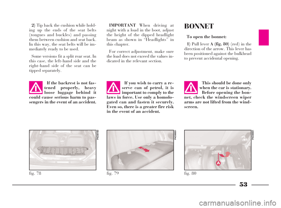
1)Pull lever A (fig. 80)(red) in the
direction of the arrow. This lever has
been positioned against the bulkhead
to prevent accidental opening.
fig. 80
P4C00001
This should be done only
when the car is stationary.
Before opening the bon-
net, check the windscreen wiper
arms are not lifted from the wind-
screen.
4C001-067 ING 11-03-2008 11:57 Pagina 53
Page 58 of 191

55
G
SKI AND
ROOF RACKS
ANCHORAGE HOOKS
POSITIONING
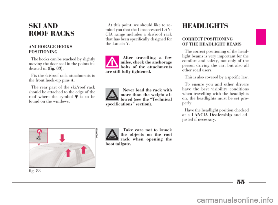
The hooks can be reached by slightly
moving the door seal in the points in-
dicated in (fig. 83).
Fix the ski/roof rack attachments to
the front hook-up pins A.
The rear part of the ski/roof rack
should be attached to the edge of the
roof where the symbol
Vis to be
found on the windows.At this point, we should like to re-
mind you that the Lineaccessori LAN-
CIA range includes a ski/roof rack
that has been specifically designed for
the Lancia Y.
fig. 83
P4C00104
After travelling a few
miles, check the anchorage
bolts of the attachments
are still fully tightened.
Never load the rack with
more than the weight al-
lowed (see the “Technical
specifications” section).
Take care not to knock
the objects on the roof
rack when opening the
boot tailgate.
HEADLIGHTS
CORRECT POSITIONING
OF THE HEADLIGHT BEAMS
The correct positioning of the head-
light beams is very important for the
comfort and safety, not only of the
person driving the car, but also all
other road users.
This is also covered by a specific law.
To ensure you and other drivers
have the best visibility conditions
when travelling with the headlights
on, the headlights must be set pro-
perly.
Have the headlight position checked
at a LANCIA Dealershipand ad-
justed if necessary.
4C001-067 ING 11-03-2008 11:57 Pagina 55
Page 59 of 191

56
G
ABS
The car is fitted with an ABS brak-
ing system that prevents the wheels
locking when braking, it exploits the
grip on the road surface holding the
car in the case of sudden braking.
The driver becomes aware of the
ABS activation through a slight throb-
bing of the brake pedal and the rele-
vant noise it makes.
This does not indicate brake mal-
functioning, it is an indication to the
driver that the ABS is operating. It is
a warning that the car is travelling at
borderline road grip and therefore the
speed should be adjusted to the type
of road surface.
The ABS is an addition to the basic
braking system; in the case of a fail-
ure it disables, leaving the braking
system in the same conditions as a ve-
hicle without ABS installed. COMPENSATION
FOR THE UPWARD SLANT
OF THE HEADLIGHT BEAMS
When the car is loaded, it “slopes”
backwards. This means that the head-
light beam rises. In this case it is nec-
essary to return it to the correct posi-
tion.
The car is fitted with an electric ad-
juster(fig. 84)situated at the side of
the handbrake:
Position0- one or two people on the
front seats.
Position1- five people.
Position2- five people + load in
luggage compartment.
Position3- driver + maximum per-
missible load all in the boot.
fig. 84
P4C00105
Check the positioning of
the headlight beams every
time you change the load
to be carried.
IMPORTANTIn order that the ad-
juster operates properly, the load in
the boot must not exceed the maxi-
mum values indicated.
ADJUSTING THE BEAM
OF THE FRONT FOGLIGHTS
Ask a LANCIA Dealershipto check
and, if necessary, adjust the beam for
you.
4C001-067 ING 11-03-2008 11:57 Pagina 56