brake Lancia Ypsilon 2002 Owner handbook (in English)
[x] Cancel search | Manufacturer: LANCIA, Model Year: 2002, Model line: Ypsilon, Model: Lancia Ypsilon 2002Pages: 191, PDF Size: 2.45 MB
Page 130 of 191
127
G
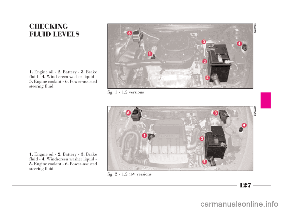
CHECKING
FLUID LEVELS
fig. 1 - 1.2 versions
P4C00385
1.Engine oil - 2.Battery - 3.Brake
fluid - 4.Windscreen washer liquid -
5.Engine coolant - 6.Power-assisted
steering fluid.
1.Engine oil - 2.Battery - 3.Brake
fluid - 4.Windscreen washer liquid -
5.Engine coolant - 6.Power-assisted
steering fluid.
fig. 2 - 1.2 16Vversions
P4C00386
4C120-143 ING 11-03-2008 12:01 Pagina 127
Page 133 of 191
130
G
POWER-ASSISTED STEERING
FLUID (fig.s 1, 2)
Check the fluid level is not below the
MINmark visible on the reservoir
with the engine cold.
If necessary, add fluid making sure
that it has the same specifications as
the fluid in the reservoir.BRAKE FLUID (fig.s 1, 2)
Check that the fluid level in the
reservoir is at maximum level.
Periodically check that the warning
light on the instrument panel is work-
ing properly by pressing on the reser-
voir cover with the key at MAR.
Warning light
xshould come on.
If you need to add fluid, only use the
type classified DOT4. You are advised
in particular to use TUTELA TOP 4
with which the braking system was
originally filled.
Symbolπon the con-
tainer indicates synthetic
type brake fluid distin-
guishing it from the mineral kind.
Using mineral type fluids damages
the special rubber braking system
gaskets beyond repair.
Make sure the power-as-
sisted steering fluid does
not come into contact with
hot parts of the engine as it catches
fire very easily.
Do not push on the power
steering limit switch for
more than 15 seconds with
the engine running. This causes
noise and could damage the sys-
tem.Oil consumption is ex-
tremely low. If further top-
ping up is required soon
after the initial top-up, have the
system checked over at a LANCIA
Dealership for leaks.
4C120-143 ING 11-03-2008 12:01 Pagina 130
Page 134 of 191

131
G
Make sure the highly cor-
rosive brake fluid does not
drip onto the paintwork. If
it does, wash it off immediately
with water.
IMPORTANTBrake fluid is hygro-
scopic (meaning it absorbs humidity).
This is why the fluid should be
changed more frequently than shown
in the Service Schedule if the car is
mainly driven in areas with a high
percentage of humidity in the air.AIR CLEANER
REPLACEMENT
1.2 versions
Loosen the screws on the edge and
on the air cleaner cover A (fig. 3)and
remove the filtering element Bto be
replaced.1.2
16Vversions
Unscrew the three screws A (fig. 4),
remove cover Band remove the filter
elementCto be replaced.
The brake fluid is poiso-
nous and corrosive. If it
accidentally comes into
contact with the skin, wash with
neutral soap and water, then rinse
copiously. If swallowed, contact a
doctor immediately.
If you often drive on
dusty roads, the filter will
require changing more fre-
quently than indicated in the Ser-
vice Schedule.
Any cleaning operations
on the filter could damage
it, causing serious damage
to the engine.
fig. 3
P4C00421
fig. 4
P4C00413
4C120-143 ING 11-03-2008 12:01 Pagina 131
Page 147 of 191
TECHNICAL SPECIFICATIONS
Motor and engineering enthusiasts as well as
those “in the trade” will probably start reading
from this point in the manual. This, in fact, is
where a section jam-packed with facts, figures,
formulae, measurements and tables begins. In a
sense, it is the Lancia Y’s identity card.
A document that introduces the car and explains
in technical jargon all the features that go together
to make it a model designed to give you superla-
tive driving satisfaction.VEHICLE IDENTIFICATION DATA ............... 145
ENGINE CODE - BODY VERSIONS............... 146
ENGINE......................................................... 147
TRANSMISSION............................................. 150
BRAKES......................................................... 151
SUSPENSION ................................................. 152
STEERING..................................................... 152
WHEELS........................................................ 153
WHEEL GEOMETRY ..................................... 155
ELECTRICAL SYSTEM ................................. 155
PERFORMANCE............................................ 156
WEIGHTS...................................................... 157
DIMENSIONS................................................. 158
CAPACITIES .................................................. 160
TYRE PRESSURE .......................................... 163
FLUIDS AND LUBRICANTS .......................... 164
FUEL CONSUMPTION -
CO
2EMISSIONS ............................................. 166
144
G
4C144-167 ING 11-03-2008 12:02 Pagina 144
Page 154 of 191

151
G
Drive transmission to the front
wheels by means of half-shafts con-
nected to the differential assembly
and the wheels with CV joints.
The ratios are:Final drive gear and differential as-
sembly incorporated in the gearbox.
Version Final drive ratio Number of teeth
1.2 3.438 16/55
1.216V3.438 16/55
1.216VM Nrosso3.867 15/58
BRAKES
SERVICE AND EMERGENCY
BRAKES
Cross-over hydraulic circuit control.
8" vacuum brake booster.
Front: disc, floating caliper type with
operating cylinder for each wheel.
Rear: drum type with self-centring
shoes with operating cylinder for each
wheel.
Automatic take up of clearance due
to friction lining wear.
Brake effort apportioning valve
working on the hydraulic circuit of
the rear brakes (for versions without
ABS).
Four channel, four sensor ABS (op-
tional for 1.2 versions, standard for LX
and 1.2
16Vversions) with electronic
brake force distributor.
HANDBRAKE
Controlled by a lever, it works me-
chanically on the rear brake shoes.
4C144-167 ING 11-03-2008 12:02 Pagina 151
Page 160 of 191
157
G
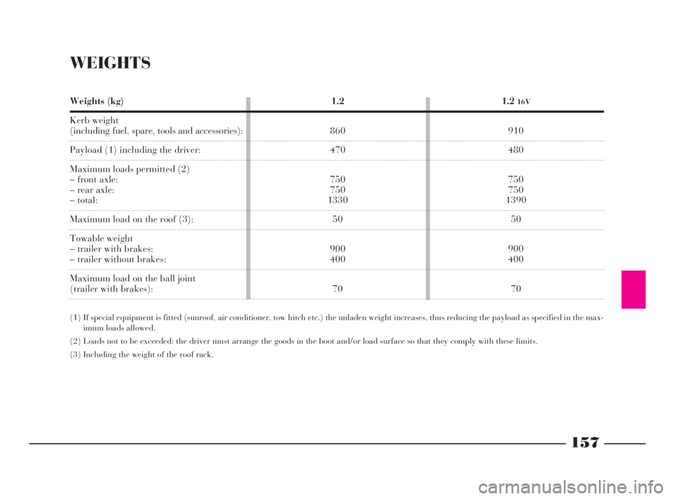
WEIGHTS
Weights (kg)
Kerb weight
(including fuel, spare, tools and accessories):
Payload (1) including the driver:
Maximum loads permitted (2)
– front axle:
– rear axle:
– total:
Maximum load on the roof (3):
Towable weight
– trailer with brakes:
– trailer without brakes:
Maximum load on the ball joint
(trailer with brakes):1.2
16V
910
480
750
750
1390
50
900
400
70 1.2
860
470
750
750
1330
50
900
400
70
(1) If special equipment is fitted (sunroof, air conditioner, tow hitch etc.) the unladen weight increases, thus reducing the payload as specified in the max-
imum loads allowed.
(2) Loads not to be exceeded: the driver must arrange the goods in the boot and/or load surface so that they comply with these limits.
(3) Including the weight of the roof rack.
4C144-167 ING 11-03-2008 12:02 Pagina 157
Page 163 of 191
160
G
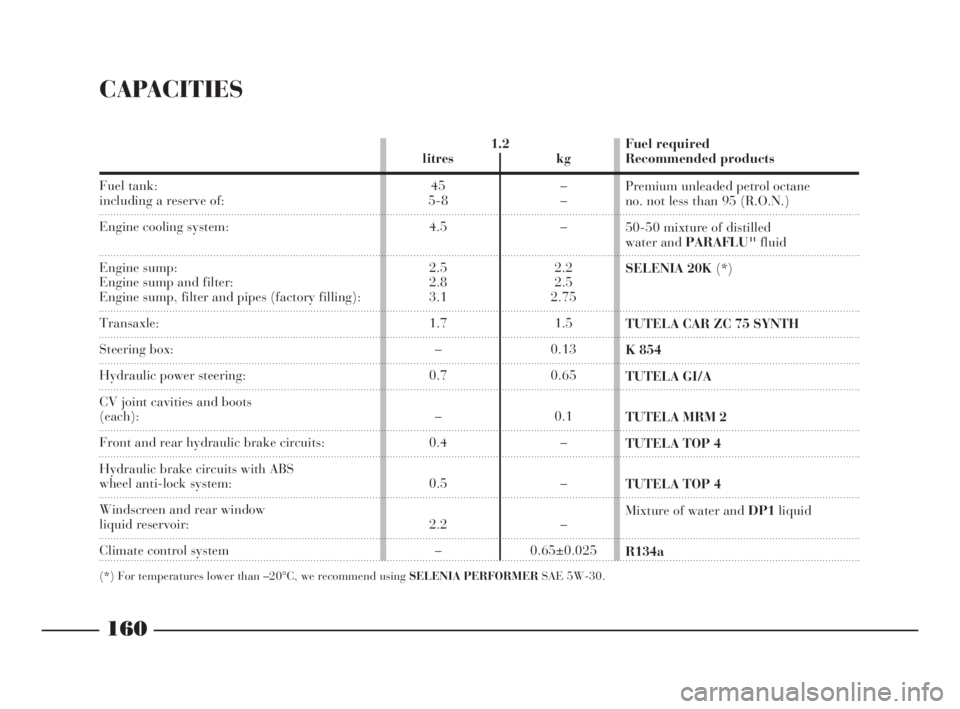
CAPACITIES
Fuel tank:including a reserve of:
Engine cooling system:
Engine sump:
Engine sump and filter:
Engine sump, filter and pipes (factory filling):
Transaxle:
Steering box:
Hydraulic power steering:
CV joint cavities and boots
(each):
Front and rear hydraulic brake circuits:
Hydraulic brake circuits with ABS
wheel anti-lock system:
Windscreen and rear window
liquid reservoir:
Climate control system
(*) For temperatures lower than –20°C, we recommend using SELENIA PERFORMERSAE 5W-30.
1.2
litres kg
45 –
5-8 –
4.5 –
2.5 2.2
2.8 2.5
3.1 2.75
1.7 1.5
–0.13
0.7 0.65
– 0.1
0.4 –
0.5 –
2.2 –
– 0.65±0.025Fuel required
Recommended products
Premium unleaded petrol octane
no. not less than 95 (R.O.N.)
50-50 mixture of distilled
water and PARAFLU
11fluid
SELENIA 20K(*)
TUTELA CAR ZC 75 SYNTH
K 854
TUTELA GI/A
TUTELA MRM 2
TUTELA TOP 4
TUTELA TOP 4
Mixture of water and DP1liquid
R134a
rs
4C144-167 ING 11-03-2008 12:02 Pagina 160
Page 164 of 191

161
G
Fuel tank:
including a reserve of:
Engine cooling system:
Engine sump:
Engine sump and filter:
Engine sump, filter and pipes (factory filling):
Transaxle:
Steering box:
Hydraulic power steering:
CV joint cavities and boots
(each):
Front and rear hydraulic brake circuits:
Hydraulic brake circuits with ABS
wheel anti-lock system:
Windscreen and rear window
liquid reservoir:
Climate control system:
(*) For temperatures lower than –20°C, we recommend using SELENIA PERFORMERSAE 5W-30.
1.216V
litres kg
45 –
5-8 –
4.5 –
2.5 2.2
2.8 2.5
3.1 2.75
1.7 1.5
–0.13
0.7 0.65
– 0.1
0.4 –
0.5 –
2.2 –
– 0.65±0.025
Fuel required
Recommended products
Premium unleaded petrol octane
no. not less than 95 (R.O.N.)
50-50 mixture of distilled
water and PARAFLU
11fluid
SELENIA 20K(*)
TUTELA CAR ZC 75 SYNTH
K 854
TUTELA GI/A
TUTELA MRM 2
TUTELA TOP 4
TUTELA TOP 4
Mixture of water and DP1liquid
R134a
4C144-167 ING 11-03-2008 12:02 Pagina 161
Page 168 of 191

165
G
Use
Drive lubricantsand grease
Steering box lubricant
Brake products
Radiatorantifreeze
Windscreen
washer liquidApplications
Manual gearbox
and differentials
CV Joints
Hydraulic
power steering
Rack steering box
Brake circuit
component
lubrication
Hydraulic brake
and clutch controls
50-50 mix
down to –35°C
To be used neat Recommended
fluids and lubricants
TUTELA CAR
ZC 75 SYNTH
TUTELA MRM 2
TUTELA GI/A
K 854
SP 349
TUTELA TOP 4
PARAFLU
11
DP1 Specifications of fluids and lubricants
to use for best car operation
SAE 75W80 EP oil exceeding API GL5 and
MIL - L - 2105 D LEV specifications
Molybdenum disulphide, lithium-soap based grease,
water-resistant NLGI consistency no. 2
ATF DEXRON II D LEV, SAE 10W oil
Lithium-soap base grease, containing molybdenum
sulphide NLGI consistency no. 000
Special grease compatible with brake fluid
Synthetic fluid: NTHSA n° 116 DOT 4 ISO 4925,
SAE J-1703, CUNA NC 956 - 01
Protective compound with ethylene glycol base
antifreeze: CUNA NC 956 - 16
Alcohol and surfactants mixture: CUNA NC 956 - 11
4C144-167 ING 11-03-2008 12:02 Pagina 165
Page 176 of 191

173
G
For mechanical connections, the fol-
lowing must be used:
– “CUNA 501” 1
stclass ball coupling
(CUNA NC 138-40 table);
– “CUNA 501” 1
stclass socket cou-
pling (CUNA NC 438-40 table).For the electric connection a 7-pole,
12 Volt coupling must be used
(CUNA UNI 9128).
The electric coupling must be fixed
on a special mount to be attached to
the ball coupling.
The electrical functions for the cou-
pling must be connected as illustrated
in(fig. 5).
In addition to the electrical connec-
tions (illustrated in the diagram that
follows), only the lead for powering
an electric brake and the lead to
power a light inside the trailer not ex-
ceeding 15W may be connected to the
car’s electrical system.
The electric brake must be powered
directly from the battery by means of
a lead with a cross-section no less
than 2.5 sq. mm.
Location of the components
on the car:
1.Left taillight (rear foglight con-
nection) - 2.Right taillight (brake
lights connection) - 3.Pole socket -
4.Trailer direction indicators power
supply relays - 5.High-amp fusebox
-6.Branching box. TOW HITCH INSTALLATION
(fig. 5)
The tow hitch must be fixed to the
body by an expert in accordance with
the following instructions and with
any additional instructions or infor-
mation provided by the tow hitch
manufacturer.
fig. 5
P4C00416
4C168-176 ING 11-03-2008 12:03 Pagina 173