fuse diagram Lancia Ypsilon 2002 Owner handbook (in English)
[x] Cancel search | Manufacturer: LANCIA, Model Year: 2002, Model line: Ypsilon, Model: Lancia Ypsilon 2002Pages: 191, PDF Size: 2.45 MB
Page 69 of 191

66
G
CELLULAR PHONE
SETUP
If the car has been ordered to in-
clude provision for the fitting of cel-
lular phones, it will have:
– one dual purpose speaker (sound
system and cellular phone) located in
the right-hand door;
– one dual purpose aerial (sound
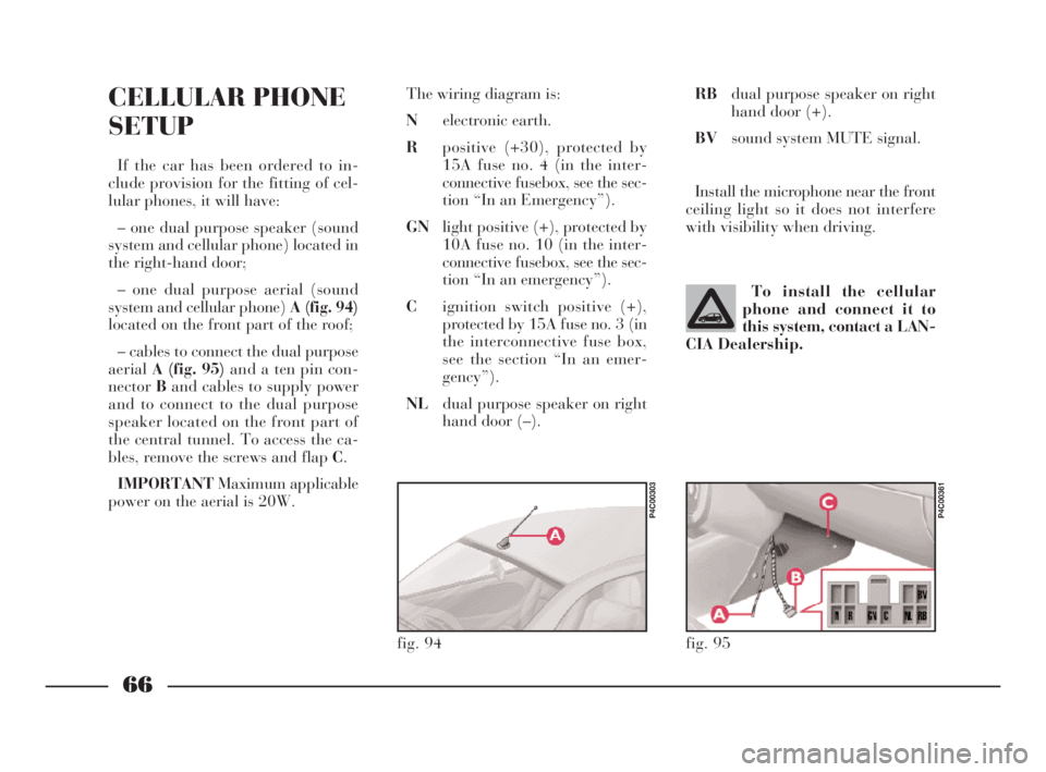
system and cellular phone) A (fig. 94)
located on the front part of the roof;
– cables to connect the dual purpose
aerialA (fig. 95)and a ten pin con-
nectorBand cables to supply power
and to connect to the dual purpose
speaker located on the front part of
the central tunnel. To access the ca-
bles, remove the screws and flap C.
IMPORTANTMaximum applicable
power on the aerial is 20W.The wiring diagram is:
Nelectronic earth.
Rpositive (+30), protected by
15A fuse no. 4 (in the inter-
connective fusebox, see the sec-
tion “In an Emergency”).
GNlight positive (+), protected by
10A fuse no. 10 (in the inter-
connective fusebox, see the sec-
tion “In an emergency”).
Cignition switch positive (+),
protected by 15A fuse no. 3 (in
the interconnective fuse box,
see the section “In an emer-
gency”).
NLdual purpose speaker on right
hand door (–).To install the cellular
phone and connect it to
this system, contact a LAN-
CIA Dealership.
fig. 94
P4C00303
RBdual purpose speaker on right
hand door (+).
BVsound system MUTE signal.
Install the microphone near the front
ceiling light so it does not interfere
with visibility when driving.
fig. 95
P4C00361
4C001-067 ING 11-03-2008 11:57 Pagina 66
Page 172 of 191

169
G
SOUND SYSTEM/RADIO NAVIGATION SYSTEM
SET-UP SYSTEM WIRING
DIAGRAM AND ADDITIONAL
BRANCHES (SOUND SYSTEM)
(fig. 1)
A- Radio aerial;
B- Terminal box;
C- High-amp fuse box;
D- Front left speaker;
E- Left tweeter;
F- Right tweeter;
G- Front right speaker;
H- Radio;
I- Rear right speaker;
L- Rear left speaker;
M- CD CHANGER (where fitted)
wire with respectiving connector,
where you can install a compatible
CD CHANGER if required;
m- +30;
n- Code positive;
o- Radio lights positive.
List of cable colour codes
N=Black - R=Red - AG=Blue/Yellow - AR=Blue/Red - CV=Orange/Green
CN=Orange/Black - BN=White-Black - GN=Yellow-Black - NZ=Black-Purple
RG=Red-Yellow - RN=Red-Black - SN=Red-Black
fig. 1
P4C00388
4C168-176 ING 11-03-2008 12:03 Pagina 169
Page 173 of 191

170
G
List of cable colour codes
G=Yellow - N=Black - R=Red - AG=Blue/Yellow - AR=Blue/Red - BR=White/Red -
CV=Orange/Green - CN=Orange/Black - BN=White-Black - GN=Yellow-Black -
NZ=Black-PurpleRG=Red-Yellow - RN=Red-Black - SN=Red-Black
SET-UP SYSTEM WIRING
DIAGRAM AND ADDITIONAL
BRANCHES (RADIO
NAVIGATION SYSTEM) (fig. 2)
A- Radio aerial;
B- Terminal box;
C- High-amp fuse box;
D- Front left speaker;
E- Left tweeter;
F- Right tweeter;
G- Front right speaker;
H- Radio-navigator;
I- Rear right speaker;
L- Rear left speaker;
M- Vehicle speed signal;
N- GPS aerial;
O- Reversing signal;
P- CD CHANGER wire with re-
spectiving connector, where you can
install a compatible CD CHANGER if
required;
m- +30;
n- +15;
o- Radio lights positive.
fig. 2
P4C00423
4C168-176 ING 11-03-2008 12:03 Pagina 170
Page 175 of 191

172
G
ELECTRICAL CONNECTION
DIAGRAM (fig. 4)
1- Connection on the branching box
for powering the relays
2- Terminal box
3- Left taillight
4- Relay for the power supply of the
trailer’s left-hand direction indicator
5- Relay for the power supply of the
trailer’s right-hand direction indicator
6- Right taillight
7- 7-pole socket
8- Rear left grounding point
9- Connection between dashboard
cables and rear cables
10- 7.5A fuse
List of cable colour codes
B=White - G- Yellow - L=Blue- M=Brown- N=Black- R=Red- V=Green
TOW HITCH
fig. 4
P4C00170
4C168-176 ING 11-03-2008 12:03 Pagina 172
Page 176 of 191

173
G
For mechanical connections, the fol-
lowing must be used:
– “CUNA 501” 1
stclass ball coupling
(CUNA NC 138-40 table);
– “CUNA 501” 1
stclass socket cou-
pling (CUNA NC 438-40 table).For the electric connection a 7-pole,
12 Volt coupling must be used
(CUNA UNI 9128).
The electric coupling must be fixed
on a special mount to be attached to
the ball coupling.
The electrical functions for the cou-
pling must be connected as illustrated
in(fig. 5).
In addition to the electrical connec-
tions (illustrated in the diagram that
follows), only the lead for powering
an electric brake and the lead to
power a light inside the trailer not ex-
ceeding 15W may be connected to the
car’s electrical system.
The electric brake must be powered
directly from the battery by means of
a lead with a cross-section no less
than 2.5 sq. mm.
Location of the components
on the car:
1.Left taillight (rear foglight con-
nection) - 2.Right taillight (brake
lights connection) - 3.Pole socket -
4.Trailer direction indicators power
supply relays - 5.High-amp fusebox
-6.Branching box. TOW HITCH INSTALLATION
(fig. 5)
The tow hitch must be fixed to the
body by an expert in accordance with
the following instructions and with
any additional instructions or infor-
mation provided by the tow hitch
manufacturer.
fig. 5
P4C00416
4C168-176 ING 11-03-2008 12:03 Pagina 173