battery Lancia Ypsilon 2012 Owner handbook (in English)
[x] Cancel search | Manufacturer: LANCIA, Model Year: 2012, Model line: Ypsilon, Model: Lancia Ypsilon 2012Pages: 307, PDF Size: 13.3 MB
Page 164 of 307

“DUALDRIVE” ELECTRIC POWER
STEERING FAILURE (red)
This warning light switches on when the ignition
key is turned to MAR, but it should switch off
after a few seconds.
If the warning light (or, on some versions, a
message and a symbol on the display) remains on,
you may not have steering assistance and the
effort required to operate the steering wheel could
be notably increased; steering is, however,
possible. In this case, contact a Lancia Dealership.
IMPORTANT In some circumstances, factors
independent of the electric power steering could
cause the warning light on the instrument panel to
switch on. In this case, stop the car immediately,
switch off the engine for about 20 seconds and
then restart the engine. If the warning light (or, on
some versions, a message and a symbol on the
display) remains on constantly, contact a Lancia
Dealership.
IMPORTANT After the battery is disconnected,
the steering must be initialised. The warning light
switches on to indicate this. To carry out this
procedure, simply turn the steering wheel all the
way from one end to the other or drive in a
straight line for about a hundred metres.
CRUISE CONTROL (green)
(for versions/markets, where provided)
This warning light switches on when the ignition
key is turned to MAR, but it should switch off
after a few seconds, if the Cruise Control is
deactivated.
The warning light switches on when the Cruise
Control ring nut is turned to the ON position (see
the “Cruise Control” paragraph in the "Knowing
your car" section). On some versions the display
shows the dedicated message.DPF (PARTICULATE FILTER) BEING
CLEANED
(only Diesel versions with DPF) (amber)
Turning the key to the MAR-ON position
illuminates the warning light, but it should switch
off after a few seconds.
The warning light (together with a message and a
symbol on the display on some versions) switches
on constantly to notify the driver that the DPF
system needs to eliminate captured pollutants
(particulate) through the regeneration process.
162
GETTING TO KNOW
YOUR CAR
SAFETY
STARTING AND
DRIVINGWARNING LIGHTS
AND MESSAGESIN AN EMERGENCY
SERVICING AND
MAINTENANCE
TECHNICAL
SPECIFICATIONS
INDEX
Page 170 of 307
IN AN EMERGENCY
In an emergency we recommend that you call the free-phone number found on the Warranty
Booklet. It is also possible to go to the www.lancia.com website to find the closest Lancia
Dealership.STARTING THE ENGINEGo to a Lancia Dealership immediately if
instrument panel warning light
remains on
constantly.
JUMP STARTING
If the battery is flat, the engine may be started
using an auxiliary battery with the same capacity
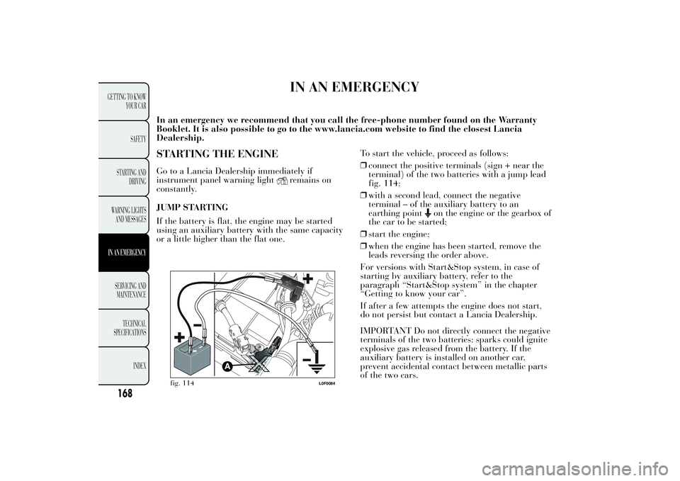
or a little higher than the flat one.To start the vehicle, proceed as follows:
❒connect the positive terminals (sign + near the
terminal) of the two batteries with a jump lead
fig. 114;
❒with a second lead, connect the negative
terminal – of the auxiliary battery to an
earthing point
on the engine or the gearbox of
the car to be started;
❒start the engine;
❒when the engine has been started, remove the
leads reversing the order above.
For versions with Start&Stop system, in case of
starting by auxiliary battery, refer to the
paragraph “Start&Stop system” in the chapter
“Getting to know your car”.
If after a few attempts the engine does not start,
do not persist but contact a Lancia Dealership.
IMPORTANT Do not directly connect the negative
terminals of the two batteries: sparks could ignite
explosive gas released from the battery. If the
auxiliary battery is installed on another car,
prevent accidental contact between metallic parts
of the two cars.
fig. 114
L0F0084
168
GETTING TO KNOW
YOUR CAR
SAFETY
STARTING AND
DRIVING
WARNING LIGHTS
AND MESSAGESIN AN EMERGENCYSERVICING AND
MAINTENANCE
TECHNICAL
SPECIFICATIONS
INDEX
Page 171 of 307
Never use a fast battery-charger to start
the engine as this could damage the
electronic systems of your car,
particularly the ignition and fuel supply
control units.
WARNING
This procedure must be performed by
expert personnel because incorrect
actions could cause electrical discharge of
considerable intensity. Furthermore, battery
fluid is poisonous and corrosive: avoid
contact with skin and eyes. Keep naked
flames and lighted cigarettes away from the
battery and do not cause sparks.
BUMP STARTING
Never jump start the engine by pushing, towing or
coasting downhill.
IMPORTANT Remember that the brake servo and
electrical power steering system are not active
until the engine is started. A much greater effort
will therefore be required to use the brake pedal or
turn the steering wheel.
REPLACING A WHEELGENERAL INSTRUCTIONS
The car is equipped with the “Fix&Go Automatic
Kit”: see the paragraph “Fix&Go Automatic
Kit” for how to use this device.
As an alternative to the “Fix&Go Automatic Kit”
the car may be equipped with a space-saver
wheel: see the instructions on the following pages
for changing the tyre.
WARNING
The space-saver wheel (for versions/
markets where provided) is specific
to your car, do not use it on other models, or
use the space-saver wheel of other models
on your car. The space-saver wheel must
only be used in case of emergency. It must
only be used for the distance necessary
to reach a service point and the car speed
must not exceed 80 km/h. The space-saver
wheel has an orange sticker that summarises
the main cautions for use and limitations.
Never remove or cover the label. The
following information is provided in four
languages on the label: "Important! For
temporary use only! 80 km/h max! Replace
with a standard tyre as soon as possible.
Never cover this indication." Never apply a
hub cap on a space-saver wheel.
169GETTING TO KNOW
YOUR CAR
SAFETY
STARTING AND
DRIVING
WARNING LIGHTS
AND MESSAGESIN AN EMERGENCYSERVICING AND
MAINTENANCE
TECHNICAL
SPECIFICATIONS
INDEX
Page 192 of 307

WARNING
If a general protective fuse for safety
systems (airbag system, braking
system), power unit systems (engine system,
transmission system) or steering system
intervenes, contact a Lancia Dealership.
FUSE LOCATION
Engine compartment fuse box
This is located next to the battery: to access fuses
fig. 154 proceed as follows:
❒move the cover A fig. 152 aside;
❒undo screw A fig. 153, release tabs B and
remove cover C by pulling upwards.The number identifying the electrical component
corresponding to each fuse is shown on the cover.
After replacing the fuse, make sure that you
have closed cover C correctly on the fuse box.
If you need to wash the engine
compartment, take care not to directly
hit the fuse box and the window wiper
motors with the water jet.
fig. 152
L0F0170
fig. 153
L0F0094
190
GETTING TO KNOW
YOUR CAR
SAFETY
STARTING AND
DRIVING
WARNING LIGHTS
AND MESSAGESIN AN EMERGENCYSERVICING AND
MAINTENANCE
TECHNICAL
SPECIFICATIONS
INDEX
Page 198 of 307
196
GETTING TO KNOW
YOUR CAR SAFETY
STARTING AND
DRIVING
WARNING LIGHTS AND MESSAGESIN AN EMERGENCYSERVICING AND MAINTENANCE TECHNICAL
SPECIFICATIONS
INDEX
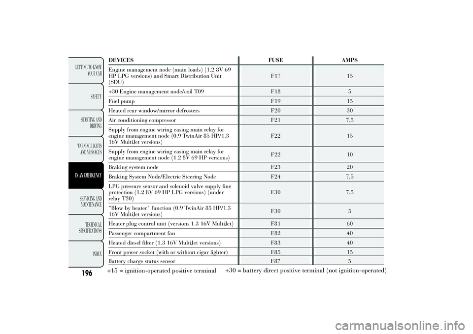
DEVICES FUSE AMPS Engine management node (main loads) (1.2 8V 69 HP LPG versions) and Smart Distribution Unit(SDU)
F17 15
+30 Engine management node/coil T09 F18 5 Fuel pump F19 15Heated rear window/mirror defrosters F20 30Air conditioning compressor F21 7,5Supply from engine wiring casing main relay for engine management node (0.9 TwinAir 85 HP/1.316V MultiJet versions)
F22 15
Supply from engine wiring casing main relay for engine management node (1.2 8V 69 HP versions)
F22 10
Braking system node F23 20 Braking System Node/Electric Steering Node F24 7,5LPG pressure sensor and solenoid valve supply line protection (1.2 8V 69 HP LPG versions) (underrelay T20)
F30 7,5
"Blow by heater" function (0.9 TwinAir 85 HP/1.3 16V MultiJet versions)
F30 5
Heater plug control unit (versions 1.3 16V MultiJet) F81 60 Passenger compartment fan F82 40Heated diesel filter (1.3 16V MultiJet versions) F83 40Front power socket (with or without cigar lighter) F85 15
Battery charge status sensor F87 5+15 = ignition-operated positive terminal +30 = battery direct positive terminal (not ignition-operated)
Page 199 of 307

INSTRUMENT PANEL FUSE BOX
fig. 156DEVICES FUSE AMPS
Free F12 -
+15 headlight alignment corrector F13 5
+15 ignition-operated control with inhibition during
engine startingF31 5
Free F32 -
+30 F36 10
+15 switch on brake pedal (NO) F37 7,5
Door central locking F38 20
Two-way windscreen washer pump F43 20
Front electric window (driver side) F47 20
Front electric window (passenger side) F48 20
+15 F49 7,5
+15 F50 7,5
+15 F51 5
+30 F53 7,5+15 = ignition-operated positive terminal
+30 = battery direct positive terminal (notignition-operated)
197GETTING TO KNOW
YOUR CAR
SAFETY
STARTING AND
DRIVING
WARNING LIGHTS
AND MESSAGESIN AN EMERGENCYSERVICING AND
MAINTENANCE
TECHNICAL
SPECIFICATIONS
INDEX
Page 201 of 307

BATTERY RECHARGINGIMPORTANT The battery recharging procedure is
given as information only. You are advised to go
to a Lancia Dealership to have this operation
performed.
Low amperage slow recharging for approximately
24 hours is advised. Charging for a longer time
may damage the battery.
VERSIONS WITHOUT Start&Stop SYSTEM
(for versions/markets, where provided)
Charge the battery as follows:
❒disconnect the negative battery terminal;
❒connect the charger cables to the battery
terminals, observing the polarity;
❒turn on the charger;
❒when finished, turn the charger off before
disconnecting the battery;
❒reconnect the negative battery terminal.
VERSIONS WITH Start&Stop SYSTEM
(for versions/markets, where provided)
Charge the battery as follows:
❒disconnect the connector A fig. 159 (pressing
the button B) from the sensor C monitoring
the battery conditions, on the negative pole D of
the battery;
fig. 159
L0F0229
199GETTING TO KNOW
YOUR CAR
SAFETY
STARTING AND
DRIVING
WARNING LIGHTS
AND MESSAGESIN AN EMERGENCYSERVICING AND
MAINTENANCE
TECHNICAL
SPECIFICATIONS
INDEX
Page 202 of 307

❒connect the positive cable of the battery charger
to the positive battery terminal E and the
negative cable to sensor terminal D as shown;
❒turn on the battery charger. At the end of the
charging process, switch the battery charger off;
❒after having disconnected the battery charger,
reconnect connector A fig. 159 to the sensor C
as shown.
WARNING
Battery fluid is poisonous and
corrosive: avoid contact with your
skin and eyes. The battery should be
charged in a well ventilated place, away
from naked flames or possible sources of
sparks: danger of explosion and fire.
WARNING
Do not attempt to charge a frozen
battery: it must be thawed first,
otherwise it may explode. If freezing has
occurred, the battery should be checked by
skilled personnel to make sure that the
internal elements are not damaged and that
the body is not cracked, with the risk of
leaking poisonous and corrosive acid.
200
GETTING TO KNOW
YOUR CAR
SAFETY
STARTING AND
DRIVING
WARNING LIGHTS
AND MESSAGESIN AN EMERGENCYSERVICING AND
MAINTENANCE
TECHNICAL
SPECIFICATIONS
INDEX
Page 207 of 307
SCHEDULED SERVICING PLANPETROL VERSIONS
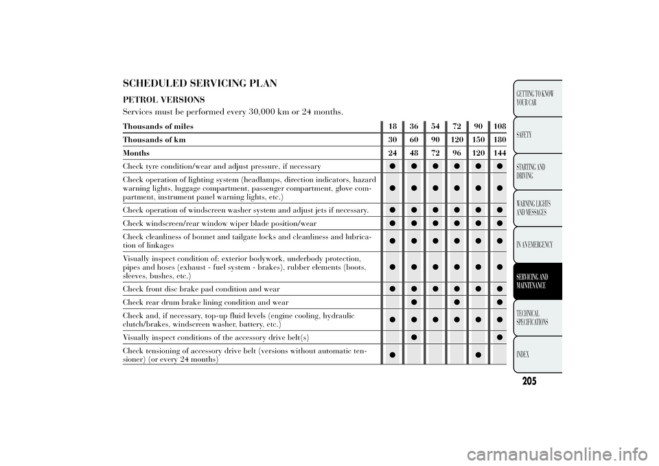
Services must be performed every 30,000 km or 24 months.Thousands of miles 18 36 54 72 90 108
Thousands of km 30 60 90 120 150 180
Months 24 48 72 96 120 144
Check tyre condition/wear and adjust pressure, if necessary●●●●●●
Check operation of lighting system (headlamps, direction indicators, hazard
warning lights, luggage compartment, passenger compartment, glove com-
partment, instrument panel warning lights, etc.)●●●●●●
Check operation of windscreen washer system and adjust jets if necessary.●●●●●●
Check windscreen/rear window wiper blade position/wear●●●●●●
Check cleanliness of bonnet and tailgate locks and cleanliness and lubrica-
tion of linkages●●●●●●
Visually inspect condition of: exterior bodywork, underbody protection,
pipes and hoses (exhaust - fuel system - brakes), rubber elements (boots,
sleeves, bushes, etc.)●●●●●●
Check front disc brake pad condition and wear●●●●●●
Check rear drum brake lining condition and wear●●●
Check and, if necessary, top-up fluid levels (engine cooling, hydraulic
clutch/brakes, windscreen washer, battery, etc.)●●●●●●
Visually inspect conditions of the accessory drive belt(s)●●
Check tensioning of accessory drive belt (versions without automatic ten-
sioner) (or every 24 months)●●
205GETTING TO KNOW
YOUR CAR
SAFETY
STARTING AND
DRIVING
WARNING LIGHTS
AND MESSAGES
IN AN EMERGENCYSERVICING AND
MAINTENANCETECHNICAL
SPECIFICATIONS
INDEX
Page 208 of 307
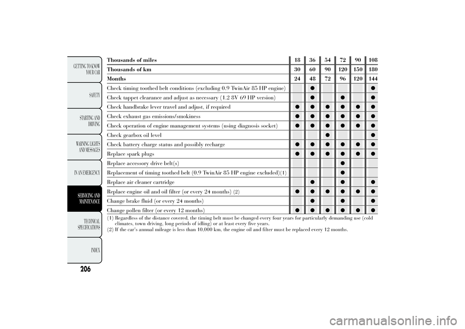
Thousands of miles 18 36 54 72 90 108
Thousands of km 30 60 90 120 150 180
Months 24 48 72 96 120 144
Check timing toothed belt conditions (excluding 0.9 TwinAir 85 HP engine)●●
Check tappet clearance and adjust as necessary (1.2 8V 69 HP version)●●●
Check handbrake lever travel and adjust, if required●●●●●●
Check exhaust gas emissions/smokiness●●●●●●
Check operation of engine management systems (using diagnosis socket)●●●●●●
Check gearbox oil level●●
Check battery charge status and possibly recharge●●●●●●
Replace spark plugs●●●●●●
Replace accessory drive belt(s)●
Replacement of timing toothed belt (0.9 TwinAir 85 HP engine excluded)
(1)
●
Replace air cleaner cartridge●●●
Replace engine oil and oil filter (or every 24 months)
(2)
●●●●●●
Change brake fluid (or every 24 months)●●●
Change pollen filter (or every 12 months)●●●●●●
(1) Regardless of the distance covered, the timing belt must be changed every four years for particularly demanding use (cold
climates, town driving, long periods of idling) or at least every five years.
(2) If the car's annual mileage is less than 10,000 km, the engine oil and filter must be replaced every 12 months.
206
GETTING TO KNOW
YOUR CAR
SAFETY
STARTING AND
DRIVING
WARNING LIGHTS
AND MESSAGES
IN AN EMERGENCYSERVICING AND
MAINTENANCE
TECHNICAL
SPECIFICATIONS
INDEX