technical specifications Lancia Ypsilon 2015 Owner handbook (in English)
[x] Cancel search | Manufacturer: LANCIA, Model Year: 2015, Model line: Ypsilon, Model: Lancia Ypsilon 2015Pages: 315, PDF Size: 10.85 MB
Page 36 of 315

WARNING
It is absolutely forbidden to carry out
any after-market operation involving
steering system or steering column
modifications (e.g.: installation of anti-theft
device) that could badly affect performance
and safety, invalidate the warranty and
also result in non-compliance of the car
with type-approval requirements.
WARNING
Never remove the key while the car is
moving. The steering wheel will lock
as soon as it is turned. This holds true for
cars being towed as well.
SEATS
WARNING
All adjustments must be made with
the car stationary.
FRONT SEATS
Lengthwise adjustment
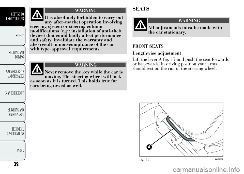
Lift the lever A fig. 17 and push the seat forwards
or backwards: in driving position your arms
should rest on the rim of the steering wheel.
fig. 17L0F0062
32
GETTING TO
KNOW YOUR CAR
SAFETY
STARTING AND
DRIVING
WARNING LIGHTS
AND MESSAGES
IN AN EMERGENCY
SERVICING AND
MAINTENANCE
TECHNICAL
SPECIFICATIONS
INDEX
Page 37 of 315

WARNING
Once you have released the
adjustment lever, always check that
the seat is locked on the guides by trying to
move it back and forth. If the seat is not
locked into place, it may unexpectedly slide
and cause the driver to lose control of the
car.
Height adjustment
(for versions/markets, where provided)
Move lever B fig. 18 upwards or downwards to
achieve the required height.
IMPORTANT Carry out the adjustment while
sitting on the seat involved (driver side or
passenger side).Backrest angle adjustment
Adjust knob C fig. 19 to obtain the required
position.
fig. 18L0F0063fig. 19L0F0064
33
GETTING TO
KNOW YOUR CAR
SAFETY
STARTING AND
DRIVING
WARNING LIGHTS
AND MESSAGES
IN AN EMERGENCY
SERVICING AND
MAINTENANCE
TECHNICAL
SPECIFICATIONS
INDEX
Page 38 of 315

Lumbar adjustment
(for versions/markets, where provided)
The position of the back against the seat backrest
can be adjusted by turning knob D fig. 20.Electric seat heating
(for versions/markets, where provided)
With the ignition key turned to MAR, press
buttons E fig. 21 to switch the function on/off.
When the function is activated, the LED on the
buttons will light up.
IMPORTANT If this function is activated with
engine off the battery will run down.
fig. 20L0F0273fig. 21L0F0247
34
GETTING TO
KNOW YOUR CAR
SAFETY
STARTING AND
DRIVING
WARNING LIGHTS
AND MESSAGES
IN AN EMERGENCY
SERVICING AND
MAINTENANCE
TECHNICAL
SPECIFICATIONS
INDEX
Page 39 of 315

HEAD RESTRAINTS
FRONT
They are height-adjustable: to adjust them,
operate as follows.
Upwards adjustment:raise the head restraint
until it clicks into place.
Downwards adjustment:press button A fig. 22
and lower the head restraint.
"Anti-Whiplash" Device
The head restraints are equipped with an
“Anti-Whiplash” device, which reduces the
distance between head and head restraint in the
event of a rear impact, thus mitigating the
"whiplash" effect.The head restraint may move when the backrest is
pressed by the occupant's torso or hand: this
behaviour is caused by the system and should not
be considered a malfunction.
WARNING
All adjustments must be made with
the car stationary. Head restraints
must be adjusted so that the head, rather
than the neck, rests on them. Only when they
are adjusted in this manner can they serve
their intended purpose.
WARNING
To make the best use of the head
restraint's protective action, adjust
the backrest so that you are sitting upright
and keep your head as close as possible
to the head restraint.
REAR
(for versions/markets, where provided)
Two height-adjustable head restraints are
provided for the rear seats. On some versions a
head restraint is also provided for the central seat.
Upwards adjustment:raise the head restraint
until it clicks into place.
fig. 22L0F0061
35
GETTING TO
KNOW YOUR CAR
SAFETY
STARTING AND
DRIVING
WARNING LIGHTS
AND MESSAGES
IN AN EMERGENCY
SERVICING AND
MAINTENANCE
TECHNICAL
SPECIFICATIONS
INDEX
Page 40 of 315

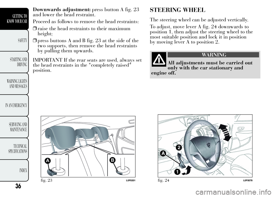
Downwards adjustment:press button A fig. 23
and lower the head restraint.
Proceed as follows to remove the head restraints:
❒raise the head restraints to their maximum
height;
❒press buttons A and B fig. 23 at the side of the
two supports, then remove the head restraints
by pulling them upwards.
IMPORTANT If the rear seats are used, always set
the head restraints in the "completely raised"
position.STEERING WHEEL
The steering wheel can be adjusted vertically.
To adjust, move lever A fig. 24 downwards to
position 1, then adjust the steering wheel to the
most suitable position and lock it in position
by moving lever A to position 2.
WARNING
All adjustments must be carried out
only with the car stationary and
engine off.
AB
fig. 23L0F0201fig. 24L0F0078
36
GETTING TO
KNOW YOUR CAR
SAFETY
STARTING AND
DRIVING
WARNING LIGHTS
AND MESSAGES
IN AN EMERGENCY
SERVICING AND
MAINTENANCE
TECHNICAL
SPECIFICATIONS
INDEX
Page 41 of 315

WARNING
It is absolutely forbidden to carry out
any after-market operation involving
steering system or steering column
modifications (e.g. installation of anti-theft
device) that could badly affect performance
and safety, invalidate the warranty and
also result in the car not meeting type-
approval requirements.
REAR VIEW MIRRORS
INTERIOR MIRROR
The mirror is fitted with a safety device that
causes its release in the event of a violent impact
with the passenger.
Operate lever A fig. 25 to adjust the mirror into
two different positions: normal or anti-glare.
fig. 25L0F0054
37
GETTING TO
KNOW YOUR CAR
SAFETY
STARTING AND
DRIVING
WARNING LIGHTS
AND MESSAGES
IN AN EMERGENCY
SERVICING AND
MAINTENANCE
TECHNICAL
SPECIFICATIONS
INDEX
Page 42 of 315

DOOR MIRRORS
Manual adjustment
From the inside of the car, operate lever A fig. 26
to adjust the mirror.Electrical adjustment
(for versions/markets, where provided)
The mirrors can be adjusted only if the ignition
key is in MAR position.
To adjust proceed as follows:
❒use switch A fig. 27 to select the mirror (left or
right) to be adjusted;
❒to adjust the mirror move the switch B in the
four directions.
fig. 26L0F0053
A
B
fig. 27L0F0190
38
GETTING TO
KNOW YOUR CAR
SAFETY
STARTING AND
DRIVING
WARNING LIGHTS
AND MESSAGES
IN AN EMERGENCY
SERVICING AND
MAINTENANCE
TECHNICAL
SPECIFICATIONS
INDEX
Page 43 of 315

Manual folding
If necessary, fold the mirrors by moving them
from position 1 (open) to position 2 (closed)
fig. 28.
IMPORTANT When driving the mirrors should
always be in position 1 (open).CLIMATE CONTROL
SIDE AIR DIFFUSERS
A fig. 29 - Adjustable and directable side air
diffusers:
❒use device B to adjust the vent to the required
position;
❒turn wheel C to adjust the air flow.
D - Fixed side air diffuser.
fig. 28L0F0220fig. 29L0F0103
39
GETTING TO
KNOW YOUR CAR
SAFETY
STARTING AND
DRIVING
WARNING LIGHTS
AND MESSAGES
IN AN EMERGENCY
SERVICING AND
MAINTENANCE
TECHNICAL
SPECIFICATIONS
INDEX
Page 44 of 315

CENTRAL AIR DIFFUSERS
A fig. 30 - Adjustable and directable central air
diffusers:
❒use device B to adjust the vent to the required
position;
❒turn wheel C to adjust the air flow.
fig. 30L0F0104
40
GETTING TO
KNOW YOUR CAR
SAFETY
STARTING AND
DRIVING
WARNING LIGHTS
AND MESSAGES
IN AN EMERGENCY
SERVICING AND
MAINTENANCE
TECHNICAL
SPECIFICATIONS
INDEX
Page 45 of 315

CLIMATIC COMFORT
DIFFUSERS
1. Upper fixed diffusers – 2. Adjustable side diffusers – 3. Fixed diffusers for side windows – 4. Adjustable centre air
diffusers – 5. Passenger compartment front foot area diffusers
fig. 31L0F0230
41
GETTING TO
KNOW YOUR CAR
SAFETY
STARTING AND
DRIVING
WARNING LIGHTS
AND MESSAGES
IN AN EMERGENCY
SERVICING AND
MAINTENANCE
TECHNICAL
SPECIFICATIONS
INDEX