brake Lancia Ypsilon 2019 Owner handbook (in English)
[x] Cancel search | Manufacturer: LANCIA, Model Year: 2019, Model line: Ypsilon, Model: Lancia Ypsilon 2019Pages: 200, PDF Size: 4.53 MB
Page 104 of 200
WARNING
118)Parking manoeuvres, however, are
always the driver’s responsibility. While
carrying out these manoeuvres, always
make sure that no people (especially
children) or animals are in the area
concerned. The parking sensors are used
to assist the driver, who must never allow
his attention to lapse during potentially
dangerous manoeuvres, even those
executed at low speeds.
WARNING
44)For correct operation of the system,
sensors must always be clean from mud,
dirt, snow or ice. Be careful not to scratch
or damage the sensors while cleaning
them. Avoid using dry, rough or hard
cloths. The sensors must be washed using
clean water, with the addition of vehicle
shampoo if necessary. When using special
washing equipment such as high pressure
jets or steam cleaning, clean the sensors
very quickly keeping the jet more than
10 cm away. Also, do not apply stickers to
the sensors.
45)Have interventions on the bumper in
the area of the sensors carried out only by
a Lancia Dealership. Interventions on the
bumper that are not carried out properly
may compromise the operation of the
parking sensors.
TOWING TRAILERS
119) 120)
IMPORTANT NOTES
For towing caravans or trailers the
vehicle must be fitted with an approved
tow hook and an adequate electrical
system. Installation must be carried out
by a specialist.
Install any specific and/or additional
door mirrors as specified by the
Highway Code.
Remember that when towing a trailer,
steep hills are harder to climb, braking
distances increase and overtaking
takes longer depending on the overall
weight of the trailer.
Engage a low gear when driving
downhill, rather than constantly using
the brake.
The weight the trailer exerts on the
vehicle tow hook reduces the vehicle's
loading capacity by the same amount.
To make sure that the maximum
towable weight is not exceeded (given
in the vehicle registration document)
account should be taken of the fully
laden trailer, including accessories and
luggage.Do not exceed the speed limits specific
to each country you are driving in, in
the case of vehicles towing trailers.
In any case, the top speed must not
exceed 100 km/h.
Any electric brake must be powered
directly by the battery through a cable
with a cross-section of no less than 2.5
mm
2.
In addition to the electrical branches,
the vehicle electrical system can only
be connected to the supply cable for an
electric brake and to the cable for an
internal light for the trailer, not
exceeding 15 W. For connections, use
the preset control unit with a battery
cable with section not less than 2.5
mm
2.
IMPORTANT The use of auxiliary loads
other than external lights (electric brake,
etc.) must take place with engine
running.
IMPORTANT To install a tow hook
contact a Lancia Dealership.
102
STARTING AND DRIVING
Page 105 of 200
WARNING
119)The ABS with which the car is
equipped will not control the braking
system of the trailer. Particular caution is
required on slippery roads.
120)Never modify the braking system of
the vehicle to control the trailer brake.
The trailer braking system must be fully
independent of the car’s hydraulic system.
REFUELLING THE
VEHICLE
46) 47) 48)
Always stop the engine before
refuelling.
PETROL ENGINES
Only use unleaded petrol, with an
octane number (R.O.N.) not lower than
95.
In order to prevent damage to the
catalytic converter never introduce even
the smallest amount of leaded petrol,
even in the event of an emergency.
DIESEL ENGINES
49)
Only use Diesel for motor vehicles (EN
590 specification).
When using or parking the vehicle for a
long time in the mountains or cold
areas, it is advisable to refuel using
locally available diesel. In this case, it is
also advisable to keep the tank over
50% full.REFUELLING
PROCEDURE
Petrol and Diesel versions equipped
with fuel tank cap
(for versions/markets, where provided)
To refuel proceed as follows:
open flap A fig. 76, pulling it
outwards;
keep the cap B still, insert the
ignition key in the lock and turn
it anticlockwise;
turn the plug anticlockwise and
remove it.
The cap has a device C fig. 76 that
attaches it to the flap so it cannot be
lost. When refilling, attach the cap
to the flap, as shown in the figure.
After refuelling, fit the plug B fig. 76
(complete with key) and turn it
clockwise until it clicks once or more.
Turn the ignition key clockwise and
remove it. Close the flap A.
76L0F0240C
103
Page 106 of 200
Petrol and Diesel versions equipped
with "Smart Fuel" system
The refuelling procedure described
below is illustrated on the label B fig. 77
located inside the fuel flap. The label
also indicates the fuel type (UNLEADED
FUEL=petrol, DIESEL=diesel fuel).
To refuel proceed as follows:
open flap A fig. 77, pulling it
outwards;
introduce the dispenser in the filler
and refuel;
after refuelling, before removing the
dispenser, wait for at least 10 seconds
in order for the fuel to flow inside the
tank;
then remove the dispenser from the
filler and close flap A.
Flap A fig. 77 is provided with a dust
cover gaiter C which prevents deposits
of impurities and dust at the end of
the filler when the flap is closed.
Emergency refuelling (only for
versions equipped with "Smart
Fuel")
Proceed as follows:
open the luggage compartment and
take the adapter B located in the tool
box (versions equipped with space-
saver wheel - for versions/markets,
where provided) fig. 78 or in the Fix&Go
Automatic container (versions
equipped with Fix&Go Automatic);
open flap A fig. 77, pulling it
outwards;
introduce the adapter B in the filler
and refuel;
after refuelling, remove the adapter
and close the flap;
reintroduce the adapter in the box
and put this back in the luggage
compartment.LPG versions
To access the filler, open the access
flap A fig. 79 and undo the cap B.
Observe the following precautions
during the refuelling operation:
switch off the engine;
apply the handbrake;
turn the ignition key to STOP;
do not smoke;
77L0F0085C
78L0F0242C
79L0F0200C
104
STARTING AND DRIVING
Page 110 of 200

Light bulbs
Use Type Power Ref. Figure
Dipped/main beam headlights H4 55 W D
Front side lights W5W 5 W TO
Daytime running lights (DRL) W21W 21 W B
Rear side lights LED - -
Front direction indicators PY24W 24W B
Side direction indicators W5W 5 W TO
Rear direction indicators PY21W 21 W B
Stop W16W 16 W B
Third brake light LED - -
Fog lights H3 55 W E
Reversing light P21W 21 W B
Rear fog light P21W 21 W B
Number plate W5W 5 W C
Front courtesy light C5W 5 W C
Luggage compartment light W5W 5 W TO
Glove compartment light C5W 5 W C
108
IN AN EMERGENCY
Page 113 of 200

refit the new lamp and carry out the
procedure described previously in
reverse.
REAR LIGHT CLUSTERS
These contain the bulbs for the side
lights, brake lights and direction
indicators. The reversing lights and rear
fog lights are located instead in the
rear bumper.
The bulbs are arranged as follows fig.
93:A- Direction indicators
B- Brake lights
Direction indicators/brake lights
Turn the bulb holder in directionO
(open) to replace the bulbs. After
replacing the bulb, turn the bulb holder
in directionC(close).
Side lights
These are LEDs. Contact a Lancia
Dealership for replacement.
THIRD BRAKE LIGHTS
These are located in the tailgate and
are LED lights. Contact a Lancia
Dealership for replacement.
REVERSING LIGHT/REAR FOG
LIGHT
To replace the bulb, proceed as follows:
working from inside the bumper,
turn the bulb holder unit A fig. 94 by a
1/4 turn;
extract the bulb and replace it;
refit the new bulb then reinsert the
bulb holder in its housing.
NUMBER PLATE LIGHTS
To replace the bulbs proceed as
follows:
remove lens A fig. 95;
turn the bulb holder B fig. 96
clockwise, extract the bulb C and
replace it; then refit the lens.
93L0F0034C
94L0F0219C
95L0F0259C
96L0F0214C
111
Page 117 of 200
DASHBOARD FUSE BOX
fig. 100
USERSFUSE AMPERE
+15 Headlight alignment corrector F13 5
+15 ignition-operated control with inhibition during engine
starting.F31 5
+30 Climate control unit, control unit, EOBD socket, radio setup F36 15
+15 switch on brake pedal (NO) F37 7.5
Central door locking F38 20
Two-way windscreen washer pump F43 20
Front electric window (driver side) F47 20
Front electric window (passenger side) F48 20
+15 Sun roof, rain/dusk sensor, electric mirror control, control
lighting, AUX socketF49 7.5
+15 Radio setup, climate control system control unit, sun roof,
parking control unit, brake pedal switch (NC), clutch pedal switch
(NC), reversing lights.F51 5
+30 Instrument panel F53 7.5
+15 = ignition-operated positive pole
+30 = battery direct positive pole (not ignition-operated)
115
Page 119 of 200
REPLACING A
WHEEL
129) 130) 131) 132) 133) 134) 135)
54) 55)
JACK
Please note that:
the jack weight is 1,76 kg;
the jack requires no adjustment;
the jack cannot be repaired and in
the event of a fault it must be replaced
by another genuine one;
no tool other than its cranking
device may be fitted on the jack.
CHANGING PROCEDURE
To change a wheel, proceed as follows:
stop the car in a position that is
not dangerous for oncoming traffic
where you can change the wheel safely.
The ground must be flat and sufficiently
compact;
switch off the engine, pull up the
handbrake and engage the 1stgear or
reverse. Wear the reflective safety
jacket (compulsory by law) before
getting out of the car;
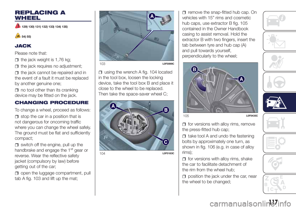
open the luggage compartment, pull
tab A fig. 103 and lift up the mat;
using the wrench A fig. 104 located
in the tool box, loosen the locking
device, take the tool box B and place it
close to the wheel to be replaced.
Then take the space-saver wheel C;
remove the snap-fitted hub cap. On
vehicles with 15” rims and cosmetic
hub caps, use extractor B fig. 105
contained in the Owner Handbook
casing to assist removal. Hold the
extractor B with two fingers, insert the
tab between tyre and hub cap (A)
and pull towards yourself,
perpendicularly to the wheel;
for versions with alloy rims, remove
the press-fitted hub cap;
take tool A and undo the fastening
bolts by approximately one turn, as
shown in fig. 106 (e.g. in case of alloy
rims);
for versions with alloy rims, shake
the car to facilitate detachment of
the rim from the wheel hub;
position the jack under the car, near
the wheel to be changed;
103L0F0099C
104L0F0183C
105L0F0435C
117
Page 122 of 200
132)The vehicle's driving characteristics
will be modified with the space-saver wheel
fitted. Avoid violent acceleration and
braking, abrupt steering and fast cornering.
The overall duration of the space-saver
wheel is of about 3000 km, after which the
relevant tyre must be replaced with another
one of the same type. Never install a
standard tyre on a rim that is designed for
use with a space-saver wheel. Have the
wheel repaired and refitted as soon as
possible. Using two or more space-saver
wheels at the same time is forbidden.
Do not apply grease to the bolt threads
before fitting: they could come unscrewed.
133)The jack shall only be used for raising
the car model it has been supplied with.
Never use the jack for other purposes,
such as raising other car models. Never
use the jack for repair operations under the
vehicle. Incorrect positioning of the jack
may cause the vehicle to fall. Do not use
the jack for loads higher than the one
shown on its label. The space-saver wheel
cannot be fitted with snow chains. If a
front (drive) tyre is punctured and chains
are needed, use a standard wheel from the
rear axle and install the space-saver wheel
on the rear axle. In this way, with two
normal drive wheels at the front axle, it is
possible to use snow chains.
134)If the hub cap is not fitted correctly, it
may come off when the car is travelling.
Never tamper with the inflation valve. Never
introduce tools of any kind between rim
and tyre. Check tyre and space-saver
wheel pressures regularly, complying with
the values given in the "Technical
specifications" chapter.135)Be very careful when removing/
refitting the hub cap due to the proximity of
the brake disc. We recommend using
heat protection gloves.
WARNING
54)When turning the jack handle make
sure that it can turn freely without scraping
your hand against the ground. The moving
components of the jack ("worm screw"
and joints) can also cause injuries: avoid
touching them. If you come into contact
with lubricating grease, clean yourself
thoroughly.
55)Contact a Lancia Dealership as soon
as possible to have the correct tightening
of the wheel bolts checked.
"Fix&Go Automatic"
KIT
136) 137) 138) 139) 140)
56)3)
DESCRIPTION
It is located in a special container in the
luggage compartment. The container
also includes a screwdriver and the tow
hook.
The kit fig. 111 also contains:
a spray bottle A with the sealant,
equipped with filling pipe B;
sticker C bearing the notice “max.
80 km/h”, to be placed in a position
visible to the driver (on the instrument
panel) after fixing the tyre;
a compressor D including a pressure
gauge and connections, found in the
compartment;
instruction brochure, to be used for
prompt and correct use of the quick
tyre repair kit and then to be handed to
the personnel charged with handling
the treated tyre;
a pair of protective gloves located in
the side compartment of the
compressor;
adapters for inflating different
elements.
120
IN AN EMERGENCY
Page 123 of 200
INFLATION PROCEDURE
141) 142) 143) 144)
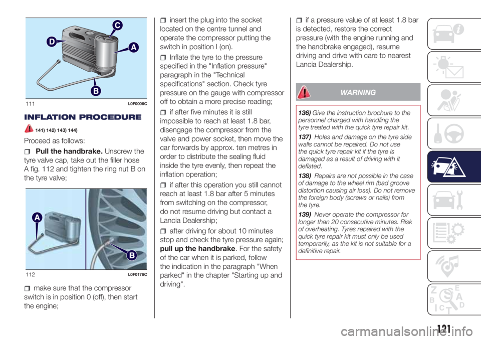
Proceed as follows:
Pull the handbrake.Unscrew the
tyre valve cap, take out the filler hose
A fig. 112 and tighten the ring nut B on
the tyre valve;
make sure that the compressor
switch is in position 0 (off), then start
the engine;
insert the plug into the socket
located on the centre tunnel and
operate the compressor putting the
switch in position I (on).
Inflate the tyre to the pressure
specified in the "Inflation pressure"
paragraph in the "Technical
specifications" section. Check tyre
pressure on the gauge with compressor
off to obtain a more precise reading;
if after five minutes it is still
impossible to reach at least 1.8 bar,
disengage the compressor from the
valve and power socket, then move the
car forwards by approx. ten metres in
order to distribute the sealing fluid
inside the tyre evenly, then repeat the
inflation operation;
if after this operation you still cannot
reach at least 1.8 bar after 5 minutes
from switching on the compressor,
do not resume driving but contact a
Lancia Dealership;
after driving for about 10 minutes
stop and check the tyre pressure again;
pull up the handbrake. For the safety
of the car when it is parked, follow
the indication in the paragraph "When
parked" in the chapter "Starting up and
driving".
if a pressure value of at least 1.8 bar
is detected, restore the correct
pressure (with the engine running and
the handbrake engaged), resume
driving and drive with care to nearest
Lancia Dealership.
WARNING
136)Give the instruction brochure to the
personnel charged with handling the
tyre treated with the quick tyre repair kit.
137)Holes and damage on the tyre side
walls cannot be repaired. Do not use
the quick tyre repair kit if the tyre is
damaged as a result of driving with it
deflated.
138)Repairs are not possible in the case
of damage to the wheel rim (bad groove
distortion causing air loss). Do not remove
the foreign body (screws or nails) from
the tyre.
139)Never operate the compressor for
longer than 20 consecutive minutes. Risk
of overheating. Tyres repaired with the
quick tyre repair kit must only be used
temporarily, as the kit is not suitable for a
definitive repair.
111L0F0006C
112L0F0176C
121
Page 127 of 200
VERSIONS WITH DUAL FUNCTION
SYSTEM GEARBOX
Make sure that the gearbox is in neutral
(N) (checking that the vehicle moves
when pushed) and proceed in the same
way as for towing a normal vehicle
with a manual gearbox.
If the gearbox cannot be put in neutral,
do not tow the car and contact a
Lancia Dealership.
WARNING
148)Before towing, turn the ignition key to
MAR-ON and then to STOP without
removing it. The steering column
will automatically lock when the key is
removed and the wheels cannot be
steered.
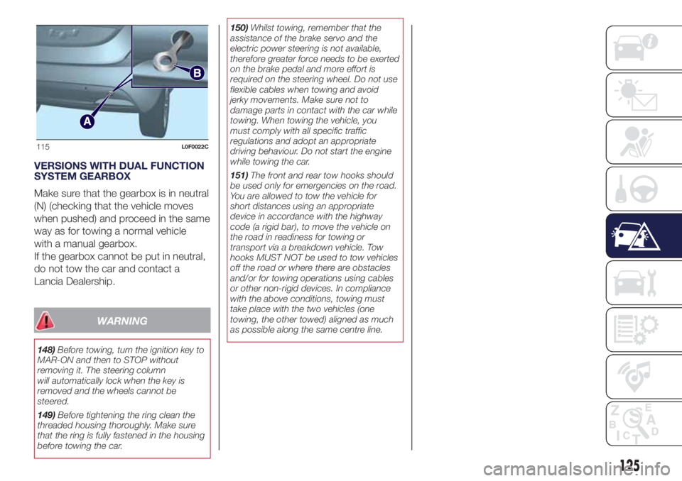
149)Before tightening the ring clean the
threaded housing thoroughly. Make sure
that the ring is fully fastened in the housing
before towing the car.150)Whilst towing, remember that the
assistance of the brake servo and the
electric power steering is not available,
therefore greater force needs to be exerted
on the brake pedal and more effort is
required on the steering wheel. Do not use
flexible cables when towing and avoid
jerky movements. Make sure not to
damage parts in contact with the car while
towing. When towing the vehicle, you
must comply with all specific traffic
regulations and adopt an appropriate
driving behaviour. Do not start the engine
while towing the car.
151)The front and rear tow hooks should
be used only for emergencies on the road.
You are allowed to tow the vehicle for
short distances using an appropriate
device in accordance with the highway
code (a rigid bar), to move the vehicle on
the road in readiness for towing or
transport via a breakdown vehicle. Tow
hooks MUST NOT be used to tow vehicles
off the road or where there are obstacles
and/or for towing operations using cables
or other non-rigid devices. In compliance
with the above conditions, towing must
take place with the two vehicles (one
towing, the other towed) aligned as much
as possible along the same centre line.
115L0F0022C
125