light Lancia Ypsilon 2020 Owner handbook (in English)
[x] Cancel search | Manufacturer: LANCIA, Model Year: 2020, Model line: Ypsilon, Model: Lancia Ypsilon 2020Pages: 200, PDF Size: 4.53 MB
Page 110 of 200

Light bulbs
Use Type Power Ref. Figure
Dipped/main beam headlights H4 55 W D
Front side lights W5W 5 W TO
Daytime running lights (DRL) W21W 21 W B
Rear side lights LED - -
Front direction indicators PY24W 24W B
Side direction indicators W5W 5 W TO
Rear direction indicators PY21W 21 W B
Stop W16W 16 W B
Third brake light LED - -
Fog lights H3 55 W E
Reversing light P21W 21 W B
Rear fog light P21W 21 W B
Number plate W5W 5 W C
Front courtesy light C5W 5 W C
Luggage compartment light W5W 5 W TO
Glove compartment light C5W 5 W C
108
IN AN EMERGENCY
Page 111 of 200

REPLACING AN
EXTERNAL BULB
FRONT LIGHT CLUSTERS
These contain the bulbs for the daytime
running lights (DRL), side lights,
dipped/main beam headlights and
direction indicators.
The bulbs are arranged as follows fig.
83:
Daytime running lights (DRL)
Dipped/main beam headlights and
side lights
Direction indicators
Daytime running lights (DRL)
To replace the bulb, proceed as follows:
remove cover A fig. 83;
turn the snap-fitted bulb holder unit
B fig. 84 anticlockwise, remove bulb
C and replace it;
refit the new bulb then reinsert the
bulb holder B fig. 84 in its housing;
then refit the cover A fig. 83.
Side lights
To replace the bulb, proceed as follows:
remove cover B fig. 83;
remove snap-fitted bulb holder C fig.
85, remove the bulb D and replace it;
refit the new bulb then reinsert
the bulb holder unit C fig. 85 in
its housing;
then refit the cover B fig. 83.
Dipped/main beam headlights
To replace the bulb, proceed as follows:
remove the cover B fig. 83 and
then the snap-fitted bulb holder C fig.
86;
remove bulb D from the connector E
and replace it;
refit the new bulb on the connector
making sure that it is locked correctly,
then reinsert bulb holder C in its
housing;
then refit the cover B fig. 83.
Front direction indicators
To replace the bulb, proceed as follows:
turn the cover C fig. 83
anticlockwise, extract the bulb D fig. 87
from its housing and replace it;
83L0F0033C
84L0F0070C
85L0F0069C
86L0F0068C
109
Page 112 of 200

refit the bulb D in the housing E and
then fit the cover C fig. 83.
Side direction indicators
To replace the bulb, proceed as follows:
adjust the lens A fig. 89 to
compress in the internal catch B, then
pull the unit outwards;
turn the bulb holder C anticlockwise,
extract the bulb and replace it;
refit the bulb holder C in the lens and
turn it clockwise;
refit the cluster making sure that the
internal catch B clips into position.
Front fog lights
(for versions/markets, where provided)
To replace the bulb, proceed as follows:
steer the wheel completely, adjust
the tabs A fig. 89 and remove the
flap B;
adjust the clip C fig. 90 and
disconnect the electrical connector D;
remove the cover E by turning it
clockwise (see the word OFF and the
arrow on the cover);
release the catches F fig. 91
removing them outwards;
release the connector G fig. 92 and
replace the bulb H;
87L0F0071C
88L0F0209C
89L0F0205C
90L0F0206C
91L0F0207C
92L0F0208C
110
IN AN EMERGENCY
Page 113 of 200

refit the new lamp and carry out the
procedure described previously in
reverse.
REAR LIGHT CLUSTERS
These contain the bulbs for the side
lights, brake lights and direction
indicators. The reversing lights and rear
fog lights are located instead in the
rear bumper.
The bulbs are arranged as follows fig.
93:A- Direction indicators
B- Brake lights
Direction indicators/brake lights
Turn the bulb holder in directionO
(open) to replace the bulbs. After
replacing the bulb, turn the bulb holder
in directionC(close).
Side lights
These are LEDs. Contact a Lancia
Dealership for replacement.
THIRD BRAKE LIGHTS
These are located in the tailgate and
are LED lights. Contact a Lancia
Dealership for replacement.
REVERSING LIGHT/REAR FOG
LIGHT
To replace the bulb, proceed as follows:
working from inside the bumper,
turn the bulb holder unit A fig. 94 by a
1/4 turn;
extract the bulb and replace it;
refit the new bulb then reinsert the
bulb holder in its housing.
NUMBER PLATE LIGHTS
To replace the bulbs proceed as
follows:
remove lens A fig. 95;
turn the bulb holder B fig. 96
clockwise, extract the bulb C and
replace it; then refit the lens.
93L0F0034C
94L0F0219C
95L0F0259C
96L0F0214C
111
Page 114 of 200
WARNING
121)Modifications or repairs to the electric
system that are not carried out properly
or do not take the system technical
specifications into account can cause
malfunctions leading to the risk of fire.
122)Halogen bulbs contain pressurised
gas, in the case of breakage they may
burst causing glass fragments to be
projected outwards.
WARNING
51)Halogen bulbs must be handled
holding the metallic part only. Touching the
transparent part of the bulb with your
fingers may reduce the intensity of the
emitted light and even reduce the lifespan
of the bulb. In the event of accidental
contact, wipe the bulb with a cloth
moistened with alcohol and let the bulb
dry.
52)If possible, we recommend that you
have bulbs replaced at a Lancia
Dealership. The correct operation and
direction of the external lights are
absolutely essential for the safety of the car
and of compliance with the law.
REPLACING FUSES
123) 124) 125) 126) 127) 128)
GENERAL
To facilitate fuse replacement, use the
pliers hooked inside the fuse box lid on
the dashboard left-hand side.
ENGINE COMPARTMENT
FUSE BOX
53)
This is located by the side of the
battery. To access the fuses, proceed
as follows:
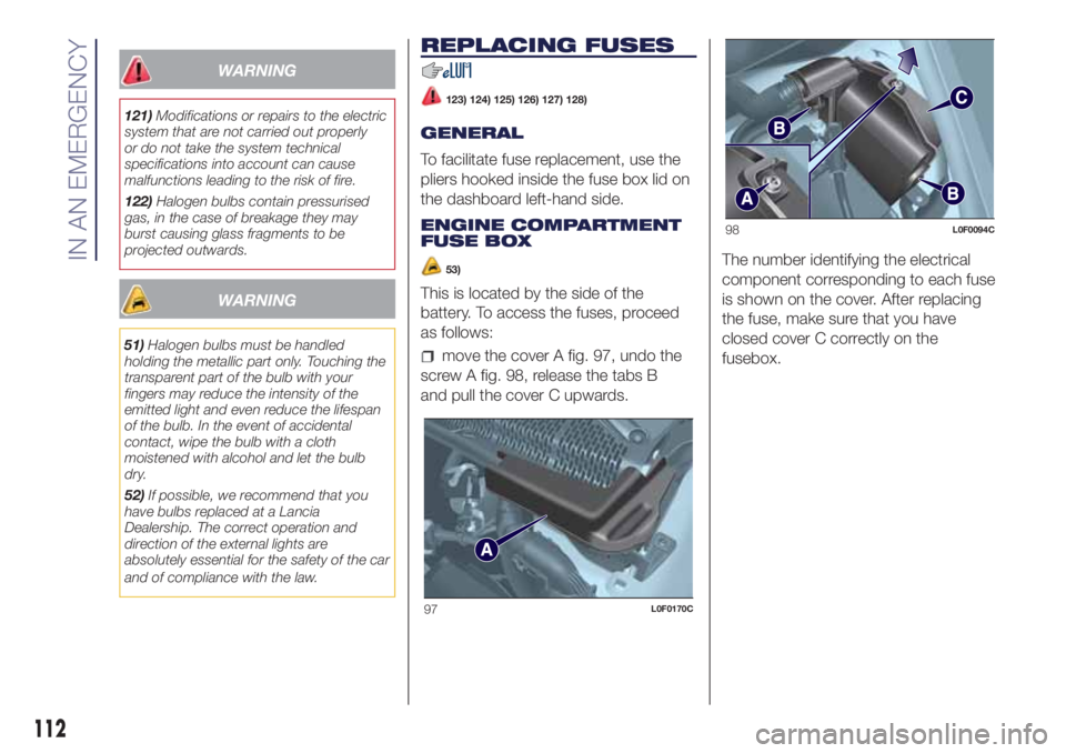
move the cover A fig. 97, undo the
screw A fig. 98, release the tabs B
and pull the cover C upwards.The number identifying the electrical
component corresponding to each fuse
is shown on the cover. After replacing
the fuse, make sure that you have
closed cover C correctly on the
fusebox.
97L0F0170C
98L0F0094C
112
IN AN EMERGENCY
Page 116 of 200
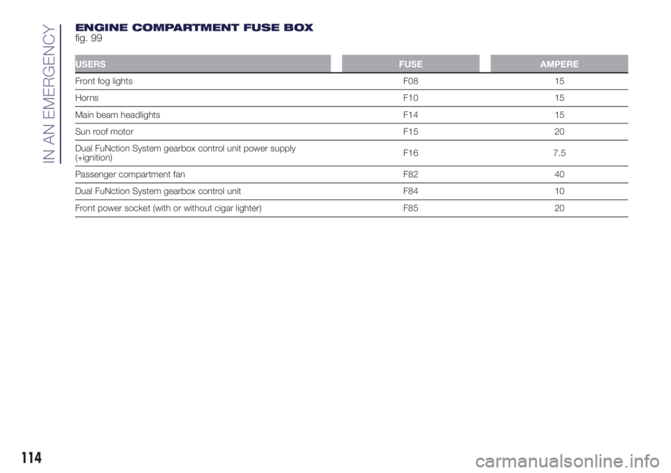
ENGINE COMPARTMENT FUSE BOX
fig. 99
USERSFUSE AMPERE
Front fog lights F08 15
HornsF10 15
Main beam headlights F14 15
Sun roof motor F15 20
Dual FuNction System gearbox control unit power supply
(+ignition)F16 7.5
Passenger compartment fan F82 40
Dual FuNction System gearbox control unit F84 10
Front power socket (with or without cigar lighter) F85 20
114
IN AN EMERGENCY
Page 117 of 200
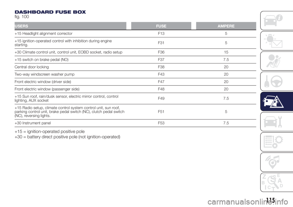
DASHBOARD FUSE BOX
fig. 100
USERSFUSE AMPERE
+15 Headlight alignment corrector F13 5
+15 ignition-operated control with inhibition during engine
starting.F31 5
+30 Climate control unit, control unit, EOBD socket, radio setup F36 15
+15 switch on brake pedal (NO) F37 7.5
Central door locking F38 20
Two-way windscreen washer pump F43 20
Front electric window (driver side) F47 20
Front electric window (passenger side) F48 20
+15 Sun roof, rain/dusk sensor, electric mirror control, control
lighting, AUX socketF49 7.5
+15 Radio setup, climate control system control unit, sun roof,
parking control unit, brake pedal switch (NC), clutch pedal switch
(NC), reversing lights.F51 5
+30 Instrument panel F53 7.5
+15 = ignition-operated positive pole
+30 = battery direct positive pole (not ignition-operated)
115
Page 121 of 200
fit the standard wheel inserting the 4
bolts into the holes;
using the wrench provided, tighten
the fastening bolts;
lower the vehicle and remove the
jack;
using the wrench provided, fully
tighten the bolts in the sequence
shown previously.
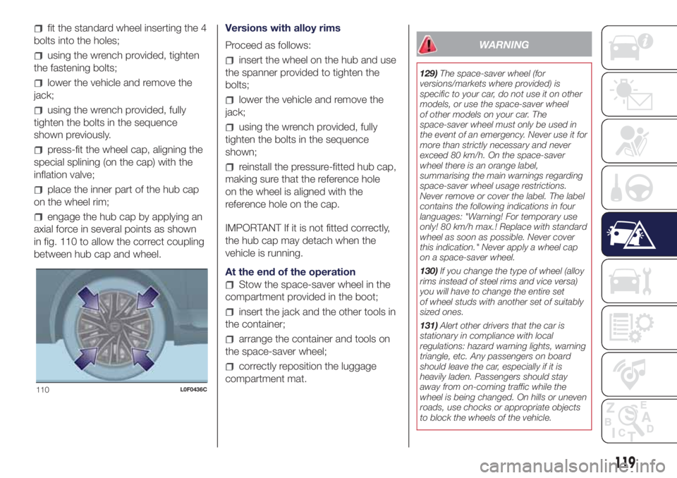
press-fit the wheel cap, aligning the
special splining (on the cap) with the
inflation valve;
place the inner part of the hub cap
on the wheel rim;
engage the hub cap by applying an
axial force in several points as shown
in fig. 110 to allow the correct coupling
between hub cap and wheel.Versions with alloy rims
Proceed as follows:
insert the wheel on the hub and use
the spanner provided to tighten the
bolts;
lower the vehicle and remove the
jack;
using the wrench provided, fully
tighten the bolts in the sequence
shown;
reinstall the pressure-fitted hub cap,
making sure that the reference hole
on the wheel is aligned with the
reference hole on the cap.
IMPORTANT If it is not fitted correctly,
the hub cap may detach when the
vehicle is running.
At the end of the operation
Stow the space-saver wheel in the
compartment provided in the boot;
insert the jack and the other tools in
the container;
arrange the container and tools on
the space-saver wheel;
correctly reposition the luggage
compartment mat.
WARNING
129)The space-saver wheel (for
versions/markets where provided) is
specific to your car, do not use it on other
models, or use the space-saver wheel
of other models on your car. The
space-saver wheel must only be used in
the event of an emergency. Never use it for
more than strictly necessary and never
exceed 80 km/h. On the space-saver
wheel there is an orange label,
summarising the main warnings regarding
space-saver wheel usage restrictions.
Never remove or cover the label. The label
contains the following indications in four
languages: "Warning! For temporary use
only! 80 km/h max.! Replace with standard
wheel as soon as possible. Never cover
this indication." Never apply a wheel cap
on a space-saver wheel.
130)If you change the type of wheel (alloy
rims instead of steel rims and vice versa)
you will have to change the entire set
of wheel studs with another set of suitably
sized ones.
131)Alert other drivers that the car is
stationary in compliance with local
regulations: hazard warning lights, warning
triangle, etc. Any passengers on board
should leave the car, especially if it is
heavily laden. Passengers should stay
away from on-coming traffic while the
wheel is being changed. On hills or uneven
roads, use chocks or appropriate objects
to block the wheels of the vehicle.
110L0F0436C
119
Page 125 of 200

with a second lead, connect the
negative terminal–of the auxiliary
battery to an earth point
on
the engine or the gearbox of the car to
be started;
start the engine;
when the engine has been started,
remove the leads reversing the order
above.
For versions with Start&Stop system, to
carry out the jump starting procedure,
refer to paragraph “Start&Stop system”
in the “Knowing your vehicle” section.
If after a few attempts the engine does
not start, do not persist but contact
a Lancia Dealership.IMPORTANT Do not directly connect
the negative terminals of the two
batteries: sparks could ignite explosive
gas released from the battery. If the
auxiliary battery is installed on another
car, prevent accidental contact
between metallic parts of the two cars.
WARNING
145)This starting procedure must be
performed by expert personnel because
incorrect actions could cause electrical
discharge of considerable intensity.
Furthermore, battery fluid is poisonous and
corrosive: avoid contact with skin and
eyes. Keep naked flames and lighted
cigarettes away from the battery and do
not cause sparks.
146)Remove any metal objects (e.g. rings,
watches, bracelets), that might cause an
accidental electrical contact and cause
serious injury.
WARNING
57)Never use a fast battery-charger to
start the engine as this could damage the
electronic systems of your vehicle,
particularly the ignition and engine fuel
supply control units.58)Do not connect the cable to the
negative terminal (–) of the flat battery. The
following spark could lead to battery
explosion and cause serious harm. Only
use the specific earth point; do not use any
other exposed metallic part.
113L0F0084C
123
Page 126 of 200
FUEL CUT-OFF
SYSTEM
147)
FUEL CUT-OFF SYSTEM
This intervenes in the case of an impact
causing:
the interruption of the fuel supply
with the engine consequently cutting
out;
the automatic unlocking of the
doors;
turning on of the lights inside the
vehicle;
the switching on of the hazard
warning lights.
On some versions, the intervention of
the system is indicated by a message
shown on the display.
IMPORTANT Carefully check the vehicle
for fuel leaks, for instance in the engine
compartment, under the vehicle or
near the tank area. After an impact, turn
the ignition key to STOP to prevent the
battery from running down.
To restore the correct operation of the
vehicle, proceed as follows:
turn the ignition key to the MAR
position;
activate the right direction indicator;
deactivate the right direction
indicator;
activate the left direction indicator;
deactivate the left direction indicator;
activate the right direction indicator;
deactivate the right direction
indicator;
activate the left direction indicator;
deactivate the left direction indicator;
ignition key turned to the OFF
position;
turn the ignition key to the MAR-ON
position.
LPG / Natural Power versions:inthe
event of an impact, petrol supply is
immediately cut-off, the LPG safety
valves are closed and the injection is
interrupted, switching off the engine.
WARNING
147)If, after an impact, you smell fuel or
notice leaks from the fuel system, do
not reactivate the system to avoid the risk
of fire.
TOWING THE
VEHICLE
148) 149) 150) 151)
The tow hook, which is supplied with
the vehicle, is housed in the tool box,
under the carpet in the luggage
compartment.
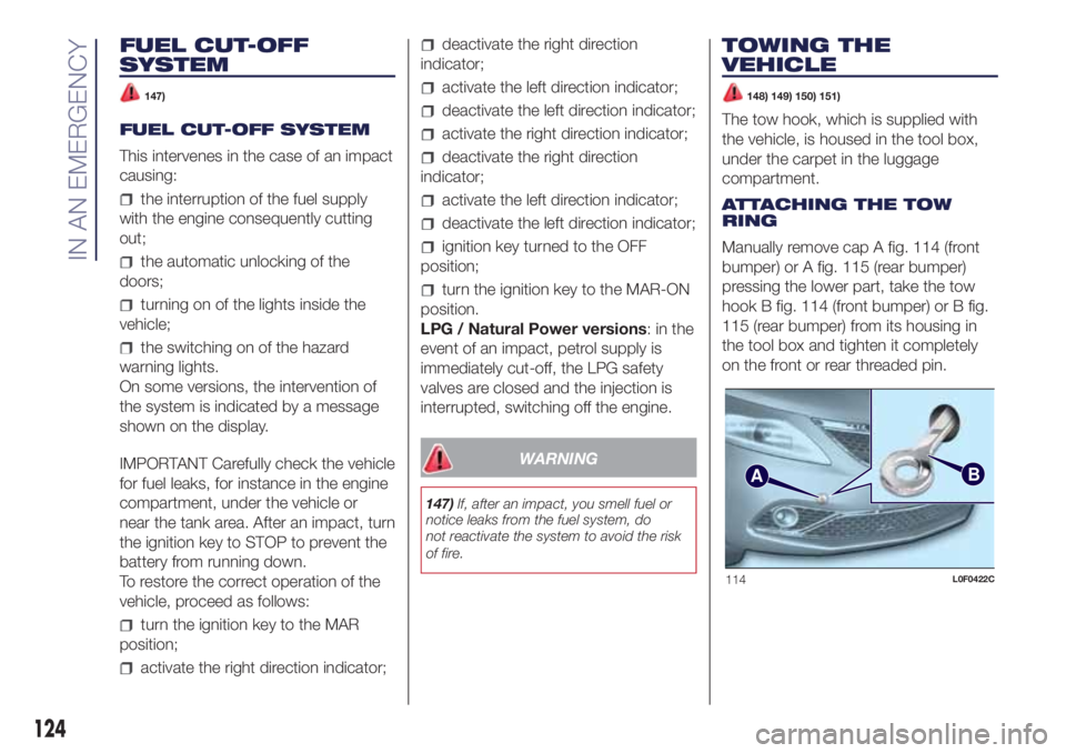
ATTACHING THE TOW
RING
Manually remove cap A fig. 114 (front
bumper) or A fig. 115 (rear bumper)
pressing the lower part, take the tow
hook B fig. 114 (front bumper) or B fig.
115 (rear bumper) from its housing in
the tool box and tighten it completely
on the front or rear threaded pin.
AB
114L0F0422C
124
IN AN EMERGENCY