Swivel LAND ROVER DEFENDER 1999 Workshop Manual
[x] Cancel search | Manufacturer: LAND ROVER, Model Year: 1999, Model line: DEFENDER, Model: LAND ROVER DEFENDER 1999Pages: 667, PDF Size: 8.76 MB
Page 28 of 667
GENERAL SPECIFICATION DATA
5
INFORMATION STEERING
Power steering box
Make/type Adwest Varamatic - worm and roller box........................................................................
Ratio Variable: straight ahead 19.3:1 on lock 14.3:1.................................................................................
Steering wheel turns, lock-to-lock 3.375....................................
Steering pump
Make/type Hobourn-Eaton series 500........................................................................
Steering geometry
Steering wheel diameter 412 mm (16.22 in)..................................................
Toe-out measurement 0 to 2 mm toe out......................................................
Toe-out included angle 0°to 0°20’ .....................................................
Camber angle 0°* ..................................................................
Castor angle 3°* .....................................................................
Swivel pin inclination static 7°* ...............................................
* Check with vehicle on level ground, in unladen
condition and five gallons of fuel. Rock the front of the
vehicle up and down to allow it to take up a normal
static position.
Turning circle between kerbs
90 models:
265/75 x 16 tyres 12,65 m (41.5 ft)..............................................................
All other tyres 11,70 m (38.4 ft)...................................................................
110 models:
750 x 16 tyres 13,41 m (44 ft)..................................................................
130 models:
750 x 16 tyres 15,24 m (50 ft)..................................................................
ProCarManuals.com
Page 54 of 667

LUBRICANTS, FLUIDS AND CAPACITIES
1
INFORMATION RECOMMENDED LUBRICANTS AND FLUIDS
All climates and conditions
AMBIENT TEMPERATURE°C
COMPONENT SPECIFICATION VISCOSITY -30 -20 -10 0 10 20 30 40 50
Td5ACEA A1 5W/30, 5W/40
Engine sump and B1 5W/50
Manual gearbox Texaco MTF94
Final drive units Molytex EP90 EP90
Swivel pin housings Texaco EP00 EP00
Power steering ATF Dexron IID,
or III
Texaco cold climate
PAS fluid 14315
Transfer box Texaco Multigear 75W-90R
LT230TE
ProCarManuals.com
Page 56 of 667
LUBRICANTS, FLUIDS AND CAPACITIES
3
INFORMATION CAPACITIES
The following capacity figures are approximate and are provided as a guide only.
Capacities (approx.)* Litres Pints
Engine sump oil - Td5 7.20...................................................... 12.67
Extra when refilling after fitting new filter 1.00.......................... 1.76
Manual gearbox 2.38............................................................... 4.19
Transfer gearbox oil 2.30......................................................... 4.00
Front differential 1.70............................................................... 3.00
Rear differential
90 Models 1.70............................................................... 3.00
110 Models 2.26............................................................. 4.00
Power steering box and reservoir LHD 2.90............................ 5.00
Power steering box and reservoir RHD 3.40............................ 6.00
Swivel pin housing oil/grease (each) 0.35................................ 0.60
Fuel tank usable fuel
90 Models 60.00............................................................... 13.20 gall
110 & 130 Models 75.00................................................... 16.50 gall
Cooling system - Td5 13.00....................................................... 22.88
Washer bottle 3,0................................................................... 5.28
NOTE: * All levels must be checked by dipstick or level plugs as applicable.
ANTI-FREEZE
PERCENTAGE CONCENTRATION - 50%
PROTECTION - LOWER TEMPERATURE LIMIT
Complete protection
Vehicle may be driven away immediately from cold,
-33°C (-36°F).
Safe limit protection
Coolant in semi-frozen state. Engine may be started
and driven away after warm-up period, -41°C (-42°
F).
Lower protection
Prevents frost damage to cylinder head, block and
radiator. Thaw out before starting engine, -47°C (-53°
F).
CAUTION: Anti-freeze content must never
be allowed to fall below 50% otherwise
damage to the engine is liable to occur.
Also, anti-freeze content should not exceed 60%
as this will greatly reduce the cooling effect of the
coolant.RECOMMENDED FUEL
Diesel fuel oil, distillate, diesel fuel, automotive gas or
Derv to British standard 2869, Class A1 or A2
Using diesel fuel with a class rating lower than stated
above could seriously impair vehicle performance.
ProCarManuals.com
Page 408 of 667

54 - FRONT AXLE AND FINAL DRIVE
CONTENTS
Page
DESCRIPTION AND OPERATION
DESCRIPTION 1.....................................................................................................
FAULT DIAGNOSIS
FAULT DIAGNOSIS 1.............................................................................................
REPAIR
FRONT AXLE ASSEMBLY 1..................................................................................
OVERHAUL
FRONT DIFFERENTIAL 1......................................................................................
FRONT HUB 1........................................................................................................
FRONT STUB AXLE, CONSTANT VELOCITY JOINT AND SWIVEL PIN
HOUSING 3............................................................................................................
ProCarManuals.com
Page 410 of 667

FRONT AXLE AND FINAL DRIVE
1
DESCRIPTION AND OPERATION DESCRIPTION
The welded steel front axle casing houses a separate
spiral bevel type differential unit, which is off-set to the
right of the vehicle centre line. The differential unit
drives the front wheels via the axle shafts and
constant velocity joints which are totally enclosed in
the spherical and swivel housings.The front wheels are pivoted on tape roller bearings at
the top and bottom of the swivel housing. The wheel
hubs on all axles are supported by two taper bearings
and driven by drive flanges which are splined to the
one piece, stub shaft/constant velocity joint.
Front axle hub and swivel housing
1.Axle casing
2.Ventilation pipe
3.Axle shaft
4.Wheel studs and hub
5.Stub axle
6.Wheel bearings
7.Inner and outer hub seals
8.Axle shaft seal
9.Hub lock plate, thrust washer and nuts
10.Brake disc
11.Drive flange
12.Shim washer and circlip13.Dust cap
14.Constant velocity joint/shaft
15.Thrust collar for CV joint
16.Roller bearing
17.Spacer
18.Circlip
19.Top and bottom swivel taper bearing
20.Top and bottom swivel pins
21.Spherical housing, seal and retainer
22.Swivel housing
23.Constant velocity shaft seal
ProCarManuals.com
Page 411 of 667

54FRONT AXLE AND FINAL DRIVE
2
DESCRIPTION AND OPERATION Lubrication
The differential, swivel pin housing and wheel hubs
are individually lubricated and separated by oil seals
(7) and (8), see J6267A, to prevent oil transfer across
the axle when the vehicle is traversing steep inclines.
The wheel bearings are lubricated with grease and the
swivel housing and differential with oil. On later
vehicles, identified by having only a filler plug in the
swivel housing, grease is used to lubricate the
housing assembly,
Ventilation
Ventilation of the differential is through a plastic pipe
(2) which terminates at a high level in the vehicle axle.
The swivel housings ventilate through axle shaft oil
seals (8) into the differential and the hub bearings
vent via the oil seals into the swivel housing.
ProCarManuals.com
Page 412 of 667

FRONT AXLE AND FINAL DRIVE
1
FAULT DIAGNOSIS FAULT DIAGNOSIS
Complaint - Oil leaks
An external leak of lubrication can be caused by a
faulty internal seal. For example, if the seals which
separate the differential from the swivel housings are
faulty and the vehicle is operating or parked on an
embankment, oil may leak across the axle leaving one
swivel with a high level and the opposite swivel and
differential lacking lubrication.
See’Description and Operation’for illustrations of oil
seal locations.
When investigating leaks or checking oil levels, it is
essential that all the lubrication is drained from any
housing with a high level and that the other levels are
checked.
Swivel oil should be checked for signs of grease
leaking from the hub bearings and oil contamination of
the hub grease.
Check that the axle ventilation system is clear, as a
blockage can cause internal pressure to force oil past
the seals.
If the vehicle is driven in deep water with defective oil
seals, water may contaminate the lubricants and when
checked, give a false impression that the housing has
been over filled with oil.
Do not assume that a high oil level is due to over
filling or, that a low level is because of an external
leak.
ProCarManuals.com
Page 414 of 667
FRONT AXLE AND FINAL DRIVE
1
REPAIR FRONT AXLE ASSEMBLY
Service repair no - 54.10.01
Remove
WARNING: Remove and refit of axle
requires a further two persons to steady
axle when lowering or repositioning axle.
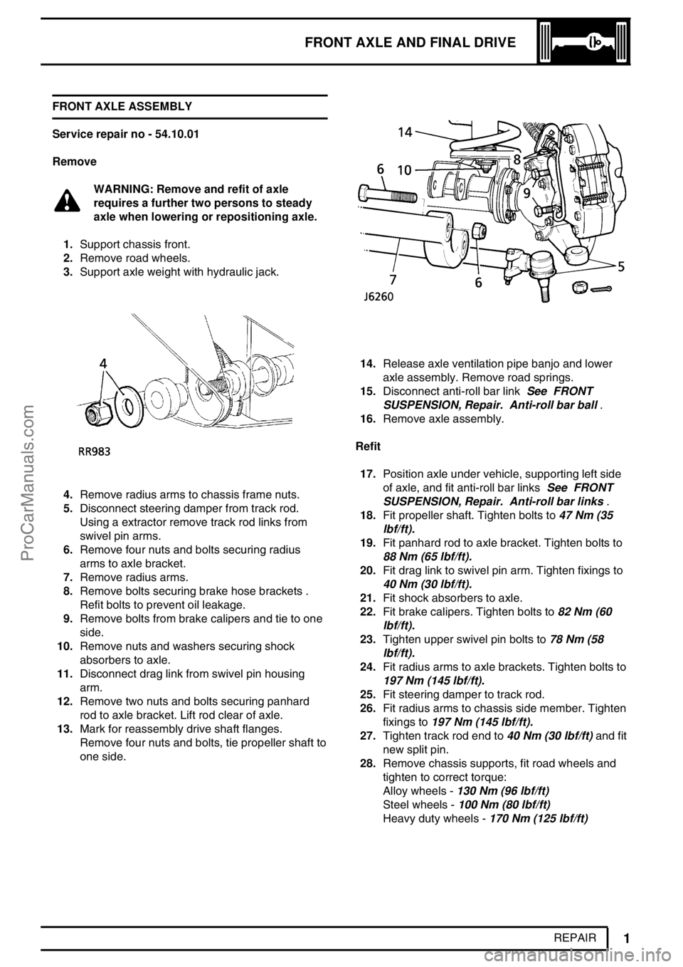
1.Support chassis front.
2.Remove road wheels.
3.Support axle weight with hydraulic jack.
4.Remove radius arms to chassis frame nuts.
5.Disconnect steering damper from track rod.
Using a extractor remove track rod links from
swivel pin arms.
6.Remove four nuts and bolts securing radius
arms to axle bracket.
7.Remove radius arms.
8.Remove bolts securing brake hose brackets .
Refit bolts to prevent oil leakage.
9.Remove bolts from brake calipers and tie to one
side.
10.Remove nuts and washers securing shock
absorbers to axle.
11.Disconnect drag link from swivel pin housing
arm.
12.Remove two nuts and bolts securing panhard
rod to axle bracket. Lift rod clear of axle.
13.Mark for reassembly drive shaft flanges.
Remove four nuts and bolts, tie propeller shaft to
one side.
14.Release axle ventilation pipe banjo and lower
axle assembly. Remove road springs.
15.Disconnect anti-roll bar linkSee FRONT
SUSPENSION, Repair. Anti-roll bar ball.
16.Remove axle assembly.
Refit
17.Position axle under vehicle, supporting left side
of axle, and fit anti-roll bar linksSee FRONT
SUSPENSION, Repair. Anti-roll bar links.
18.Fit propeller shaft. Tighten bolts to47 Nm (35
lbf/ft).
19.Fit panhard rod to axle bracket. Tighten bolts to
88 Nm (65 lbf/ft).
20.Fit drag link to swivel pin arm. Tighten fixings to
40 Nm (30 lbf/ft).
21.Fit shock absorbers to axle.
22.Fit brake calipers. Tighten bolts to82 Nm (60
lbf/ft).
23.Tighten upper swivel pin bolts to78 Nm (58
lbf/ft).
24.Fit radius arms to axle brackets. Tighten bolts to
197 Nm (145 lbf/ft).
25.Fit steering damper to track rod.
26.Fit radius arms to chassis side member. Tighten
fixings to197 Nm (145 lbf/ft).
27.Tighten track rod end to40 Nm (30 lbf/ft)and fit
new split pin.
28.Remove chassis supports, fit road wheels and
tighten to correct torque:
Alloy wheels -130 Nm (96 lbf/ft)
Steel wheels -100 Nm (80 lbf/ft)
Heavy duty wheels -170 Nm (125 lbf/ft)
ProCarManuals.com
Page 418 of 667

FRONT AXLE AND FINAL DRIVE
3
OVERHAUL FRONT STUB AXLE, CONSTANT VELOCITY JOINT
AND SWIVEL PIN HOUSING
Service repair no - 60.15.43.
Remove stub axle, axle shaft and constant
velocity joint.
1.Remove front hub assemblySee FRONT
SUSPENSION, Repair. Front hub bearings.
2.Drain swivel pin housing and refit plug.
NOTE: On later vehicles the swivel pin
housing is filled with grease for life, the
level and drain plugs being deleted.
3.Remove 6 bolts retaining stub axle to swivel
housing.
4.Remove mud shield.
5.Remove stub axle and joint washer.
6.Wthdraw axle shaft and constant velocity joint
from axle casing.
Remove constant velocity joint from axle shaft
7.Hold axle shaft firmly in a soft jawed vice.
8.Using a soft mallet drive constant velocity joint
from shaft.
9.Remove circlip and collar from axle shaft.
Constant velocity joint
10.Mark positions of constant velocity joint, inner
and outer race and cage for reassembly.
11.Swivel cage and inner race to remove balls.
ProCarManuals.com
Page 420 of 667

FRONT AXLE AND FINAL DRIVE
5
OVERHAUL Swivel pin housing
22.Remove bolts securing oil seal retaining plate
and joint washer. Release assembly from swivel
pin housing.
NOTE: Removal of oil seal and retaining
plate is achieved when swivel bearing
housing is removed.
23.Remove 2 bolts, retaining lower swivel pin to
housing.
24.Remove brake disc shield bracket.
25.Tap lug to remove lower swivel pin and joint
washer.
26.Remove two bolts retaining brake hose bracket
and top swivel pin.
27.Remove bracket, top swivel pin and shims.
28.Remove swivel pin housing while retrieving
lower and upper bearings.
Swivel bearing housing
29.Remove lower bearing track from swivel bearing
housing.
NOTE: Use upper bearing opening to gain
access to lower bearing track.
30.Remove 7 bolts retaining swivel bearing housing
to axle case.
31.Remove inner oil seal from back of housing.
32.Remove top bearing track from swivel bearing
housing.
NOTE: Use lower bearing opening to gain
access to upper bearing track.
33.If worn, pitted or damaged, renew housing.
34.Fit upper and lower bearing tracks into swivel
bearing housing.
CAUTION: Ensure bearing tracks are fitted
square or damage could occur.
35.With seal lips trailing, fit swivel housing inner oil
seal into rear of housing. Grease seal lips.
Fit swivel pin housing
36.Coat swivel bearing housing to axle casing bolts
with Loctite 270 or equivalent.
37.Coat both sides of joint washer with a sealing
compound. Position swivel bearing housing to
axle mating face.Swivel assembly components
1.Swivel pin housing
2.Top swivel pin and brake hose bracket
3.Upper and lower swivel pin bearings
4.Shim
5.Retaining plate and washer
6.Oil seal
7.Joint washer
8.Swivel bearing housing
9.Joint washer
10.Lower swivel pin
11.Mudshield bracket
12.Swivel housing inner oil seal
ProCarManuals.com