service indicator LAND ROVER DEFENDER 1999 Workshop Manual
[x] Cancel search | Manufacturer: LAND ROVER, Model Year: 1999, Model line: DEFENDER, Model: LAND ROVER DEFENDER 1999Pages: 667, PDF Size: 8.76 MB
Page 83 of 667

10MAINTENANCE
24
MAINTENANCE ENDORSE SERVICE RECORD
1.Insert date and mileage of next service.
2.Insert current mileage.
3.Tick one of the boxes on the brake fluid
replacement indicator.
4.Endorse service record with dealer stamp.
5.Sign and date the service record.
6.Sign and date the maintenance check sheet.REPORT ANY UNUSUAL FEATURES
1.Produce a written report detailing additional work
necessary, or items which may require attention
prior to the next service.
ProCarManuals.com
Page 126 of 667

ENGINE
1
REPAIR CAMSHAFT
Service repair no - 12.13.02
Remove
1.Remove cylinder head gasket.See this
Section.
2.Note the gasket thickness indicator and ensure
the same thickness gasket is used on refitment
of cylinder head.
3.Disconnect multiplug from injector units and
remove harness from camshaft carrier.
4.Remove and discard multiplug’O’ring.
5.Loosen lock nuts and fully retract rocker
adjusting screws.
6.Progressively loosen then remove and discard 6
bolts securing rocker shaft, remove shaft.
7.Using sequence shown, progressively loosen
then remove 13 bolts securing camshaft carrier
to cylinder head.
8.Gently tap the camshaft carrier upwards to break
the sealant bond and remove carrier noting it is
located by 2 dowels.
9.Remove camshaft.
10.Remove and discard camshaft rear oil seal.
11.Remove and discard lock nuts and rocker
adjusting screws.
12.Check bearing surfaces in cylinder head and
camshaft carrier for signs of scoring and wear.
ProCarManuals.com
Page 167 of 667

12ENGINE
8
OVERHAUL CYLINDER HEAD - OVERHAUL
Service repair no - 12.29.19.01
Dismantling
1.Remove cylinder head gasket.See this
Section.
CAUTION: Due to the design of the
cylinder head which incorporates drillings
for the fuel injection system, it is important
that absolute cleanliness is adhered to when
carrying out overhaul procedures.
2.Note the gasket thickness indicator and ensure
the same thickness gasket is used on refitment
of cylinder head.
CAUTION: If new pistons, connecting rods
or crankshaft are fitted, it will be
necessary to determine thickness of
gasket required.See this Section.
3.Remove 4 glow plugs.
4.Disconnect multiplugs from EUI’s and remove
harness from camshaft carrier. Remove and
discard’O’ring from harness multiplug.
5.Loosen lock nuts and fully unscrew rocker
adjusting screws; discard locknuts and screws.
6.Remove and discard 6 bolts securing rocker
shaft, remove shaft.
NOTE: Dowel located.
7.Using sequence shown, progressively loosen 13
bolts securing camshaft carrier to cylinder head
until valve spring pressure is released; remove
bolts.
CAUTION: Do not discard bolts at this
stage.
ProCarManuals.com
Page 476 of 667

CHASSIS AND BODY
7
REPAIR Refit
29.Fit bonnet cable grommet.
30.Fit side repeater lamp to wing.
31.Fit headlamp sealing ring, fit headlamp and
tighten screws.
32.Fit headlamp finisher, side and indicator lamps
and tighten screws.
33.Fit grille support bracket and tighten bolt.
34.With assistance, position and align wing to body
and locate bonnet cable to wing.
35.Connect headlamp, indicator, side lamp and side
repeater lamp multiplugs.
36.Fit bolt securing wing to bulkhead.
37.Fit bolts securing wing to’A’post.
38.Fit nut and bolt securing support stay to wing.
39.Fit bolt securing inner and outer wing to chassis.
40.Fit bolts securing radiator bracket to wing.
41.Fit bolts securing outer wing to inner wing.
42.Align wing and finally tighten all bolts.
43.Position wheel arch extension to wing, and fit
securing studs.
44.Position PAS reservoir to wing and tighten bolts.
45.Position expansion tank pipe and secure with
studs.
46.Position EGR solenoid and tighten bolts.
47.Position heater air intake seal and fit air intake.
48.Fit heater air intake bracket and tighten bolts.
49.Fit heater air intake grille and tighten screws.
50.Align air cleaner intake elbow, tighten screws
and fit grille.
51.Fit wheel arch liner.See this Section.
52.Position bonnet release cable to lock and tighten
screw.
53.Fit cooling fan cowl.
54.Fit front grille.See this Section.STEP - FOLDING - REAR DOOR
Service repair no - 76.10.41
Remove
1.Remove 2 bolts securing step to chassis
member, remove step and collect spacers.
Refit
2.Position step, fit spacer washers and tighten
bolts.
ProCarManuals.com
Page 644 of 667

ELECTRICAL
5
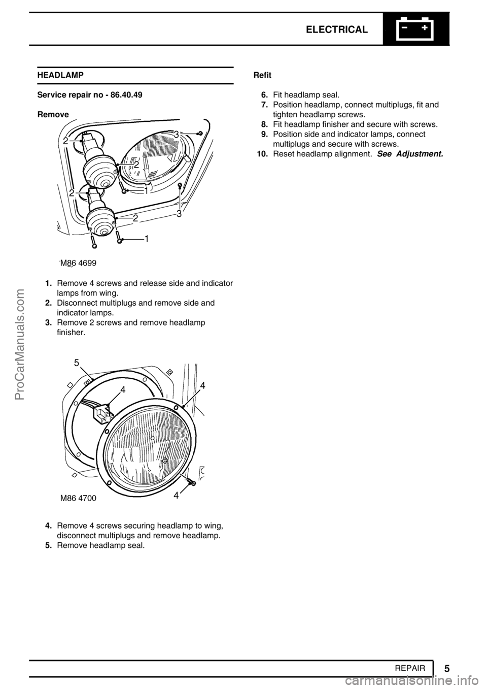
REPAIR HEADLAMP
Service repair no - 86.40.49
Remove
1.Remove 4 screws and release side and indicator
lamps from wing.
2.Disconnect multiplugs and remove side and
indicator lamps.
3.Remove 2 screws and remove headlamp
finisher.
4.Remove 4 screws securing headlamp to wing,
disconnect multiplugs and remove headlamp.
5.Remove headlamp seal.Refit
6.Fit headlamp seal.
7.Position headlamp, connect multiplugs, fit and
tighten headlamp screws.
8.Fit headlamp finisher and secure with screws.
9.Position side and indicator lamps, connect
multiplugs and secure with screws.
10.Reset headlamp alignment.See Adjustment.
ProCarManuals.com