clock LAND ROVER DISCOVERY 1999 User Guide
[x] Cancel search | Manufacturer: LAND ROVER, Model Year: 1999, Model line: DISCOVERY, Model: LAND ROVER DISCOVERY 1999Pages: 1529, PDF Size: 34.8 MB
Page 789 of 1529

FRONT SUSPENSION
60-44 REPAIRS
Refit
1.Clean mating faces of pulley and ACE pump.
2.Position pulley to ACE pump and fit bolts.
Restrain pulley and tighten bolts to 25 Nm (18
lbf.ft).
3.Clean mating faces of ACE pump and
mounting.
4.Connect suction hose to ACE pump and secure
with clip.
5.Ensure there is sufficient fluid in ACE/PAS
reservoir to prime ACE pump.
6.Position ACE pump below level of ACE/PAS
reservoir, with suction hose uppermost, and
allow fluid from ACE/PAS reservoir to
completely fill ACE pump.
7.Position ACE pump to mounting, fit bolts and
tighten to 25 Nm (18 lbf.ft).
8.Rotate ACE pump clockwise (viewed from
pulley end) until a steady flow of fluid runs from
outlet port.
9.Connect pressure pipe to ACE pump with banjo
bolt and new sealing washers. Tighten banjo
bolt to 28 Nm (21 lbf.ft).
10.Connect hose to intercooler and secure with
clip.
11.Fit ACE/PAS reservoir into mounting bracket.
12.Connect air hose to turbo charger and secure
with clip.
13.Fit mass air flow sensor to air filter and secure
with clips.
14.Connect multiplugs to mass air flow sensor and
ambient air pressure sensor.
15.Fit auxiliary drive belt.
+ CHARGING AND STARTING,
REPAIRS, Belt - auxiliary drive.
16.Renew ACE high pressure filter.
+ FRONT SUSPENSION, REPAIRS,
Filter - high pressure - ACE.
Valve block - ACE
$% 60.60.20
CAUTION: The ACE hydraulic system is
extremely sensitive to the ingress of dirt or
debris. The smallest amount could render the
system unserviceable. It is imperative that the
following precautions are taken.
lACE components are thoroughly cleaned
externally before work commences;
lall opened pipe and module ports are
capped immediately;
lall fluid is stored in and administered
through clean containers.
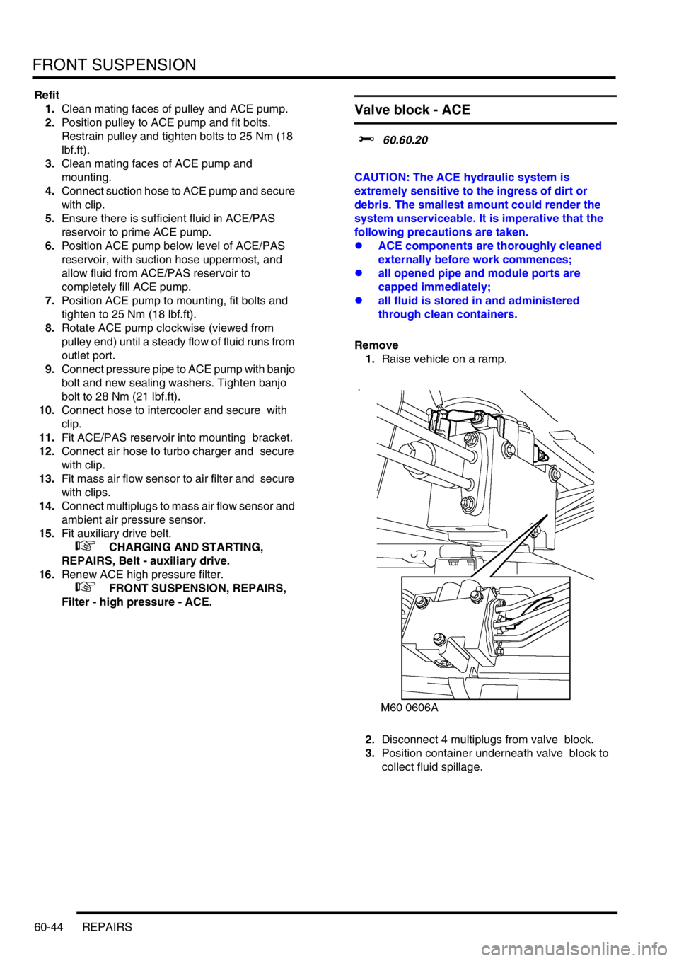
Remove
1.Raise vehicle on a ramp.
2.Disconnect 4 multiplugs from valve block.
3.Position container underneath valve block to
collect fluid spillage.
Page 882 of 1529

BRAKES
ADJUSTMENTS 70-29
ADJUST ME NTS
Handbrake
$% 70.45.09
Check
1.Apply the handbrake lever 3 notches on the
ratchet. The handbrake should be fully
operational.
2.If the handbrake is not fully operational, the
brake shoes and/or the handbrake cable need
adjusting.
Adjust
1.Raise rear of vehicle.
WARNING: Do not work on or under a
vehicle supported only by a jack. Always
support the vehicle on safety stands.
2.Ensure handbrake lever is fully released.
3.Tighten brake shoe adjusting bolt until brake
drum is locked, then back off adjusting bolt 1.5
turns. Check that the brake drum is free to
rotate.
4.Recheck handbrake operation.If handbrake is
not fully applied with 3 notches on the
ratchet, the handbrake cable requires
adjustment.
5.Remove switch panel from centre console.
+ WINDOWS, REPAIRS, Switch -
console.
6.Release handbrake lever gaiter from centre
console.7.Rotate adjuster anti-clockwise to increase
cable tension (reduce notches) or clockwise to
decrease cable tension (increase notches).
8.Recheck handbrake operation.
9.Secure handbrake lever gaiter to centre
console.
10.Fit switch panel to centre console.
+ WINDOWS, REPAIRS, Switch -
console.
11.Remove stand(s) and lower vehicle.
Page 981 of 1529

INTERIOR TRIM COMPONENTS
76-3-16 REPAIRS
Louvre panel assembly - centre fascia
$% 76.46.42
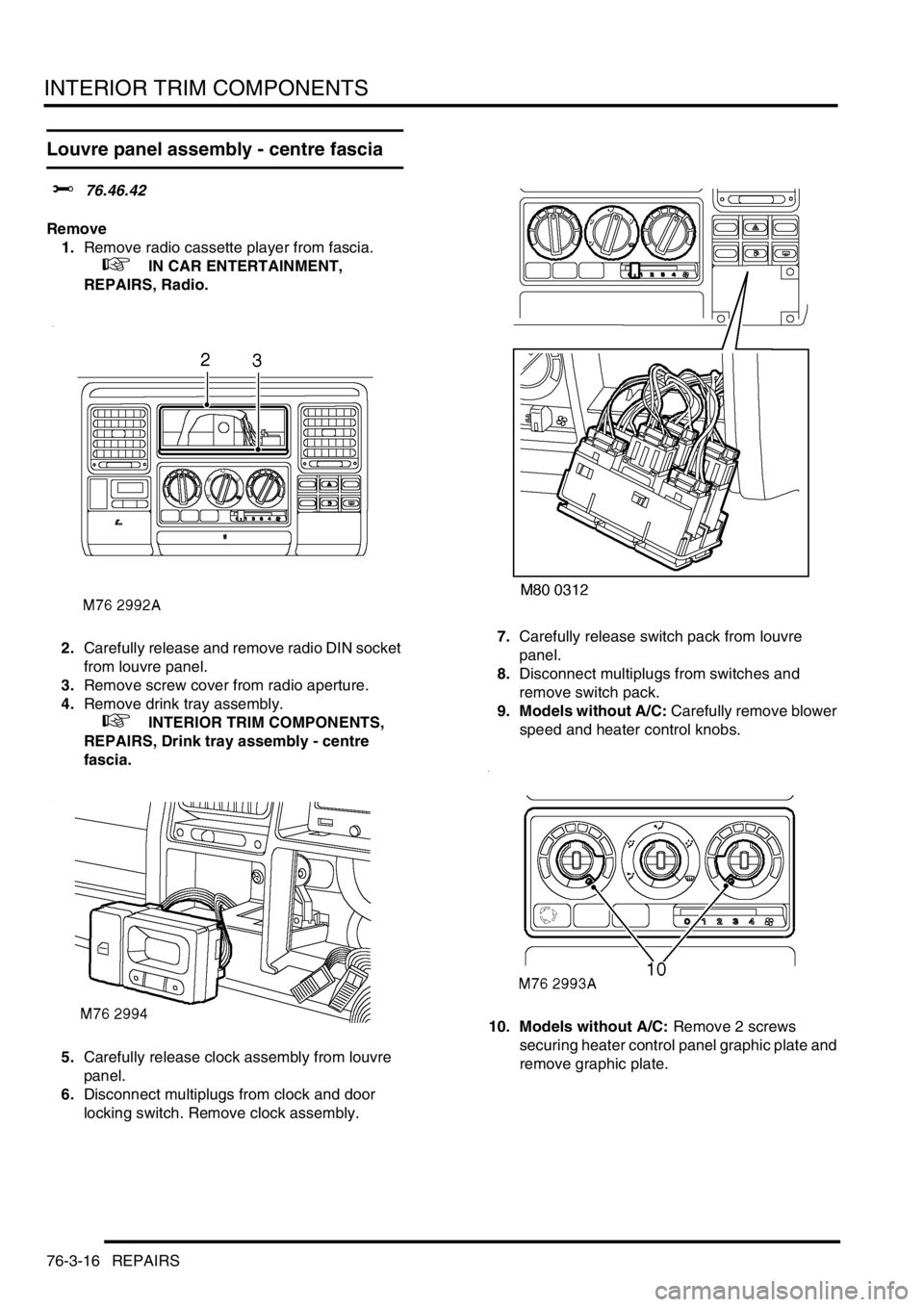
Remove
1.Remove radio cassette player from fascia.
+ IN CAR ENTERTAINMENT,
REPAIRS, Radio.
2.Carefully release and remove radio DIN socket
from louvre panel.
3.Remove screw cover from radio aperture.
4.Remove drink tray assembly.
+ INTERIOR TRIM COMPONENTS,
REPAIRS, Drink tray assembly - centre
fascia.
5.Carefully release clock assembly from louvre
panel.
6.Disconnect multiplugs from clock and door
locking switch. Remove clock assembly.7.Carefully release switch pack from louvre
panel.
8.Disconnect multiplugs from switches and
remove switch pack.
9. Models without A/C: Carefully remove blower
speed and heater control knobs.
10. Models without A/C: Remove 2 screws
securing heater control panel graphic plate and
remove graphic plate.
Page 982 of 1529

INTERIOR TRIM COMPONENTS
REPAIRS 76-3-17
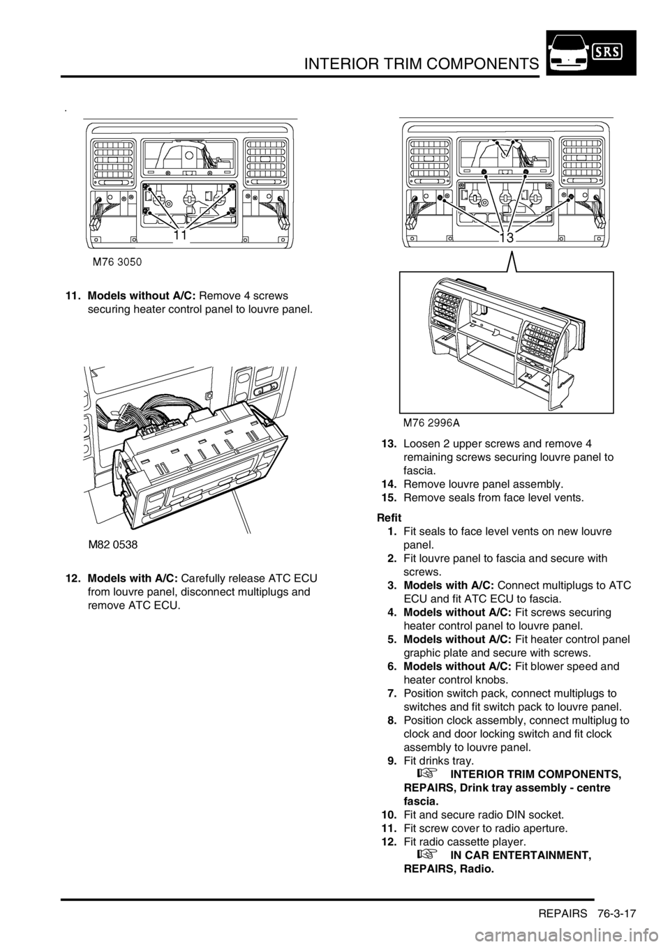
11. Models without A/C: Remove 4 screws
securing heater control panel to louvre panel.
12. Models with A/C: Carefully release ATC ECU
from louvre panel, disconnect multiplugs and
remove ATC ECU.13.Loosen 2 upper screws and remove 4
remaining screws securing louvre panel to
fascia.
14.Remove louvre panel assembly.
15.Remove seals from face level vents.
Refit
1.Fit seals to face level vents on new louvre
panel.
2.Fit louvre panel to fascia and secure with
screws.
3. Models with A/C: Connect multiplugs to ATC
ECU and fit ATC ECU to fascia.
4. Models without A/C: Fit screws securing
heater control panel to louvre panel.
5. Models without A/C: Fit heater control panel
graphic plate and secure with screws.
6. Models without A/C: Fit blower speed and
heater control knobs.
7.Position switch pack, connect multiplugs to
switches and fit switch pack to louvre panel.
8.Position clock assembly, connect multiplug to
clock and door locking switch and fit clock
assembly to louvre panel.
9.Fit drinks tray.
+ INTERIOR TRIM COMPONENTS,
REPAIRS, Drink tray assembly - centre
fascia.
10.Fit and secure radio DIN socket.
11.Fit screw cover to radio aperture.
12.Fit radio cassette player.
+ IN CAR ENTERTAINMENT,
REPAIRS, Radio.
Page 1025 of 1529

SEATS
76-5-28 REPAIRS
Cover - squab - front seat
$% 78.90.08/81
Remove
1.Remove front seat.
+ SEATS, REPAIRS, Seat - front.
2.Place seat on a suitable work bench.
3.Tighten arm rest adjuster fully clockwise and
remove screw cover.
4.Remove screw securing arm rest to seat and
remove arm rest.
5.Remove 2 screws securing outer edge trim
casing to seat frame.
6.Remove trim casing.
7.Release inner edge of trim casing from seat
frame.
8.Remove trim casing. 9.Position seat upside down on table.
10.Release clip securing lower edge of squab
cover to seat frame.
11.Remove 2 clips securing either end of cover to
squab frame.
12.Position seat in upright position.
13.Raise headrest to maximum height.
14.Turn both guides through 90°.
15.Remove headrest from seat.
16.Remove screws securing grab handles to seat
frame and remove grab handles.
Page 1269 of 1529

CHARGING AND STARTING
86-1-4 REPAIRS
Belt - auxiliary drive
$% 86.10.03
Remove
1.Remove viscous fan:
l
+ COOLING SYSTEM - V8,
REPAIRS, Fan - viscous.
l
+ COOLING SYSTEM - Td5,
REPAIRS, Fan - viscous.
2.Turn drive belt tensioner using a 15 mm ring
spanner and release belt from pulleys.
Refit
1.Clean drive belt pulley grooves and ensure
grooves are not damaged.
2.Fit new drive belt around pulleys, ensure belt is
correctly aligned in pulley grooves.
3.With assistance, hold tensioner fully clockwise
and fit drive belt around remaining pulley.
Release tensioner.
4.Fit viscous fan:
l
+ COOLING SYSTEM - Td5,
REPAIRS, Fan - viscous.
l
+ COOLING SYSTEM - V8,
REPAIRS, Fan - viscous.
Battery
$% 86.15.01
Remove
1.Release fixings and remove battery cover.
2.Disconnect both battery leads, negative lead
first.
3.Remove lock nuts and retaining nuts securing
battery clamp.
4.Remove battery clamp.
5.Remove battery.
Refit
1.Clean battery terminals and coat with
petroleum jelly.
2.Fit battery.
3.Fit battery clamp and tighten retaining nuts and
lock nuts.
4.Fit both battery leads, negative lead last.
5.Fit battery cover and secure fixings.
Page 1334 of 1529

ALARM SYSTEM AND HORN
DESCRIPTION AND OPERATION 86-4-11
Central door locking switches
A momentary action switch mounted on the fascia allows for central door locking/unlocking from within the vehicle.
The switch is mounted adjacent to the clock.
Input/Output
The input from the central door locking/unlocking switch to the BCU is either zero volts or an open circuit. Zero volts
indicates the switch is closed. An open circuit indicates that the switch is open. When the BCU sees an open circuit,
it pulls the input high internally.
The central door locking/unlocking switch has a dedicated signal input to the BCU. This allows the BCU to identify
the lock/ unlock request.
TestBook provides the ability to monitor the real time state of the central door locking/ unlocking switch.
Page 1348 of 1529

ALARM SYSTEM AND HORN
REPAIR 86-4-25
REPAIR
Switch - central door locking
$% 86.26.30
Remove
1.Carefully remove clock assembly from louvre
panel.
2.Disconnect multiplug from door lock switch.
3.Remove door lock switch from clock.
Refit
1.Fit door lock switch to clock assembly.
2.Connect multiplug to door lock switch.
3.Position clock assembly and push to secure in
position.
Switches - horn
$% 86.30.01
Remove
WARNING: It is imperative that before any
work is undertaken on the SRS system the
appropriate information is read thoroughly.
1.Disconnect both battery leads, negative lead
first, and wait 10 minutes.
2.Remove driver's airbag module.
+ RESTRAINT SYSTEMS, REPAIRS,
Airbag module - drivers.
3.Release horn switch multiplugs and leads from
steering wheel base.
4.Disconnect horn switch multiplugs from
harness.
5.Disconnect horn switch multiplug from rotary
coupler harness.
6.Remove screw securing earth leads to steering
wheel.
7.Using a broad round edged tool, carefully prise
horn switches from steering wheel.
Refit
1.Fit to steering wheel and connect multiplugs.
2.Fit earth leads and secure with screw.
3.Secure leads and multiplugs to base of steering
wheel.
4.Fit driver's airbag module.
+ RESTRAINT SYSTEMS, REPAIRS,
Airbag module - drivers.
Page 1458 of 1529

NAVIGATION SYSTEM
DESCRIPTION AND OPERATION 87-5
System Settings Menu
The system settings menu provides access to features that can be changed to suit market and personal preferences
and to navigation system operating features. On European systems, the system settings menu also includes
computer games and a currency converter. While the navigation computer is in the navigation mode, the system
settings menu can be accessed by pressing the Nav button. Using the RH rotary control, the following features can
be selected and adjusted:
lTIME – Allows the navigation system clock to be set to local time as opposed to the Greenwich Mean Time (GMT)
transmitted from the GPS satellites. The local time setting is necessary for correct navigation on routes with time
restrictions and for Estimated Time of Arrival (ETA) calculations. The time can only be adjusted in 30 minute
steps.
lSAVE POSITION– Allows the current vehicle position to be saved and allocated a name in the navigation
destination memory.
lGAMES – Provides access to a selection of computer games.
lLANGUAGE– Allows the navigation system language and voice (where applicable) to be changed.
lANIMATIONS– Allows the LCD animations to be switched on and off.
lMEASURING UNIT – Allows the route guidance distances displayed on the LCD to be switched between metric
and Imperial units.
lANNOUNCEMENT ETA – Allows the route guidance ETA announcement to be switched on and off.
lCALCULATE EURO – Provides access to a currency converter.
User Menu
The user menu provides access to further features that can be changed to suit personal preferences. While the
navigation computer is in navigation, radio or CD modes, the user menu can be accessed by pressing and holding
the tone button for more than 2 seconds. The user menu is displayed over two screens, which can be toggled between
using the ⇒ multifunction button. Using the appropriate multifunction button or the RH rotary control, the following
settings can be selected and adjusted:
Screen 1
lGal – Automatic volume control setting (see above).
lTel – If a handsfree telephone system is connected to the navigation computer, allows either mute (telephone
mute mode) or audio signal (telephone conversation via the ICE speakers) to be selected.
lLcd – The LCD can be set to appear negative, positiveor automatic. In automatic, the display will be positive or
negative, depending on the setting of the exterior lamps.
lLed – A Light Emitting Diode (LED) in the display can be set to off or blinking. When set to blinking, the LED
flashes when the navigation computer is switched off.
lM/S – Radio reception can be set to Stereo, Mono or Auto, to suppress interference and reflections and so
optimise reception. Stereo is for exceptionally good reception conditions. Mono is for poor reception conditions.
In auto, the normal setting, the navigation computer automatically switches between stereo and mono depending
on reception conditions.
Screen 2
lNav – Sets how audio navigation instructions are delivered. In onl, other audio sources are suppressed and only
the navigation instruction is output to the speakers. In mixed, the volume of any other audio source is reduced
and the volume of the navigation announcement is the same as the original audio source +/– 6 dB (adjustable).
In independ, the audio source and navigation announcement can be set to independent volume levels.
lAux – Used to switch auxiliary CD AF connections between Aux mode on and Aux mode off. If no CD
autochanger is installed, an external cassette or CD player can be connected to the navigation computer and
powered by switching on the auxiliary CD AF connections.
lCmp – Allows a compass to be shown on the LCD when route guidance is not active.
lBeV – Used to adjust the signal tone volume. Signal tones sound to confirm storage confirmation etc. and can
be set between 0 (quiet) and +5 (loud).
Page 1461 of 1529

NAVIGATION SYSTEM
87-8 DESCRIPTION AND OPERATION
Calibration Routine
1Park the vehicle outside in an area clear of high buildings, trees etc.
NOTE: The more open the surrounding area is, the faster the system will acquire sufficient GPS satellite signals to
begin calibration. To minimise the calibration time, the vehicle should not be moved again until the calibration
ride.
2Turn the ignition switch to position II. If the navigation computer does not come on, press the navigation
computer ON button.
3If necessary, use the navigation computer multifunction buttons to enter the security code.
4Turn the ignition switch to position 0 and remove the ignition key.
5Press the navigation computer ON button.
6Call up the SENSORS screen on the LCD:
lIf the navigation CD-ROM has not been installed before, press and hold multifunction button 1 then press
multifunction button 10.
lIf the navigation CD-ROM has been installed before, use the garage menu as detailed above.
7Turn the LH rotary control to minimum volume.
8Wait for 30 minutes. If necessary, the vehicle can be left unattended and locked.
NOTE: Land Rover recommend a minimum of 30 minutes be allowed to elapse in order to ensure that only a short
distance need be driven to achieve calibration.
9After the 30 minutes have elapsed, ensure the navigation computer LCD shows a GPS almanac figure of 27 or
higher.
10Start the vehicle engine and allow to idle.
11Install the navigation CD-ROM.
12Wait until the navigation computer LCD prompts for a language to be selected. Turn the RH rotary control to
scroll through the options, highlight the required language and press the RH rotary control to select.
13The navigation computer LCD will prompt for a voice to be selected. Turn the RH rotary control to scroll through
the options, highlight the required voice and press the RH rotary control to select.
14Wait until the navigation computer LCD advises "language has been loaded OK". Press the RH rotary control to
confirm the language and voice selections.
15The navigation computer LCD will default to the CALIBRATION RIDE screen and should show the
CALIBRATION RIDE CAN START message. The GPS data and the road speed counter will also be shown.
16Drive the vehicle over a road route approximating that shown below (it is not necessary to copy the route
exactly). Calibration is complete when the navigation computer LCD switches to show DESTINATION & POI
and the satellite graphic. If all the pre calibration ride conditions were complied with, calibration is typically
achieved within 3 miles (5 km) and usually occurs when the vehicle returns to the start point. However,
calibration may be achieved earlier in the journey and, if it is, there is no need to complete the remainder of the
calibration route.
17After calibration is achieved, return to the dealership, park the vehicle and stop the engine.
18Turn the ignition switch to position I.
19Use the system settings menu to set the navigation computer to local time and the required units of measure:
aPress the Nav button.
bTurn the RH rotary control to scroll through the displayed menu, highlight TIME and press the RH rotary
control to select. Press the + or – multifunction button to adjust the time in 30 minute steps. Select the 24
hour clock and confirm by pressing the OK multifunction button.
cIf metric units of measure are required, go to step e) (the navigation computer defaults to metric units of
measure).
dIf Imperial units of measure are required, turn the RH rotary control to scroll through the displayed menu,
highlight MEASURING UNIT and press the RH rotary control to select. Turn the RH rotary control to
highlight IMPERIAL and press the RH rotary control to select.
ePress the Nav button to return to the destination menu.
20Calibration is complete. The navigation system is ready for use.
NOTE: The accuracy of the system will automatically be fine tuned when a further journey is made, but this is not
required as part of the calibration procedure.
NOTE: In European countries, the territory will have to be set the first time the navigation system is used, and the
first time a destination in another country is selected. The first time the navigation system is used or a destination
in another country is selected, a map is displayed with the default/current territory highlighted. To change the
territory: Press the RH rotary control to display the territory list; turn the RH rotary control to scroll through the
list and highlight the required territory; press the RH rotary control to confirm the selection.