fuel filter LAND ROVER DISCOVERY 1999 Owner's Manual
[x] Cancel search | Manufacturer: LAND ROVER, Model Year: 1999, Model line: DISCOVERY, Model: LAND ROVER DISCOVERY 1999Pages: 1529, PDF Size: 34.8 MB
Page 287 of 1529

EMISSION CONTROL - V8
17-2-54 REPAIRS
8.Remove and discard clip securing fuel leak
detection pump fuel pipe to the EVAP canister
and disconnect the fuel pipe.
9.Remove the EVAP canister.
Refit
1.Position EVAP canister to the mounting
bracket.
2.Connect fuel leak detection pump fuel pipe to
the EVAP canister and secure with a new clip.
3.Fit nut and bolt securing EVAP canister to the
mounting bracket and tighten to 10 Nm (7 lbf.ft).
4.Position EVAP canister retaining clamp to the
mounting bracket, fit bolt and tighten to 10 Nm
(7 lbf.ft).
5.Position EVAP canister mounting bracket to the
chassis, fit new bolts and tighten to 25 Nm (18
lbf.ft).
6.Connect vent pipes to the EVAP canister.
7.Connect multiplug to the fuel leak detection
pump.
8.Connect the fuel leak detection filter pipe to the
fuel leak detection pump.
9.Lower the vehicle lift.
Valve - purge control
$% 17.15.39
Remove
1.Disconnect multiplug from purge control valve.
2.Release clips securing hoses to purge control
valve.
3.Disconnect hoses from purge control valve and
remove valve.
CAUTION: Always fit plugs to open
connections to prevent contamination.
Refit
1.Position purge control valve and connect
hoses.
2.Fit clips to secure hoses to purge control valve.
3.Connect multiplug to purge control valve.
Page 297 of 1529
EMISSION CONTROL - V8
17-2-64 REPAIRS
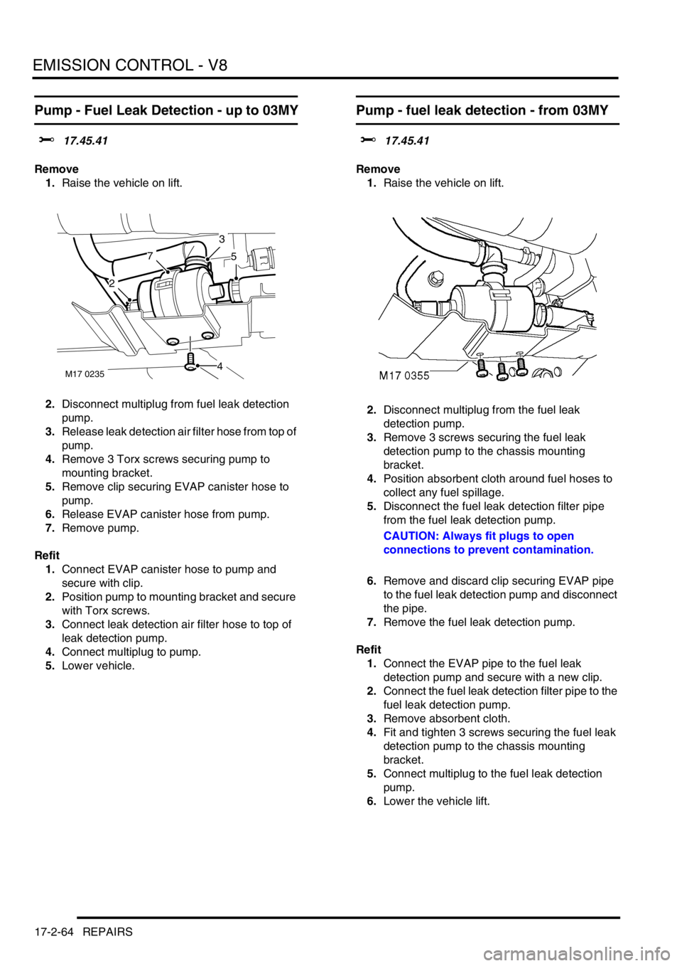
Pump - Fuel Leak Detection - up to 03MY
$% 17.45.41
Remove
1.Raise the vehicle on lift.
2.Disconnect multiplug from fuel leak detection
pump.
3.Release leak detection air filter hose from top of
pump.
4.Remove 3 Torx screws securing pump to
mounting bracket.
5.Remove clip securing EVAP canister hose to
pump.
6.Release EVAP canister hose from pump.
7.Remove pump.
Refit
1.Connect EVAP canister hose to pump and
secure with clip.
2.Position pump to mounting bracket and secure
with Torx screws.
3.Connect leak detection air filter hose to top of
leak detection pump.
4.Connect multiplug to pump.
5.Lower vehicle.
Pump - fuel leak detection - from 03MY
$% 17.45.41
Remove
1.Raise the vehicle on lift.
2.Disconnect multiplug from the fuel leak
detection pump.
3.Remove 3 screws securing the fuel leak
detection pump to the chassis mounting
bracket.
4.Position absorbent cloth around fuel hoses to
collect any fuel spillage.
5.Disconnect the fuel leak detection filter pipe
from the fuel leak detection pump.
CAUTION: Always fit plugs to open
connections to prevent contamination.
6.Remove and discard clip securing EVAP pipe
to the fuel leak detection pump and disconnect
the pipe.
7.Remove the fuel leak detection pump.
Refit
1.Connect the EVAP pipe to the fuel leak
detection pump and secure with a new clip.
2.Connect the fuel leak detection filter pipe to the
fuel leak detection pump.
3.Remove absorbent cloth.
4.Fit and tighten 3 screws securing the fuel leak
detection pump to the chassis mounting
bracket.
5.Connect multiplug to the fuel leak detection
pump.
6.Lower the vehicle lift.
M17 0235
2
3
4
57
Page 298 of 1529
EMISSION CONTROL - V8
REPAIRS 17-2-65
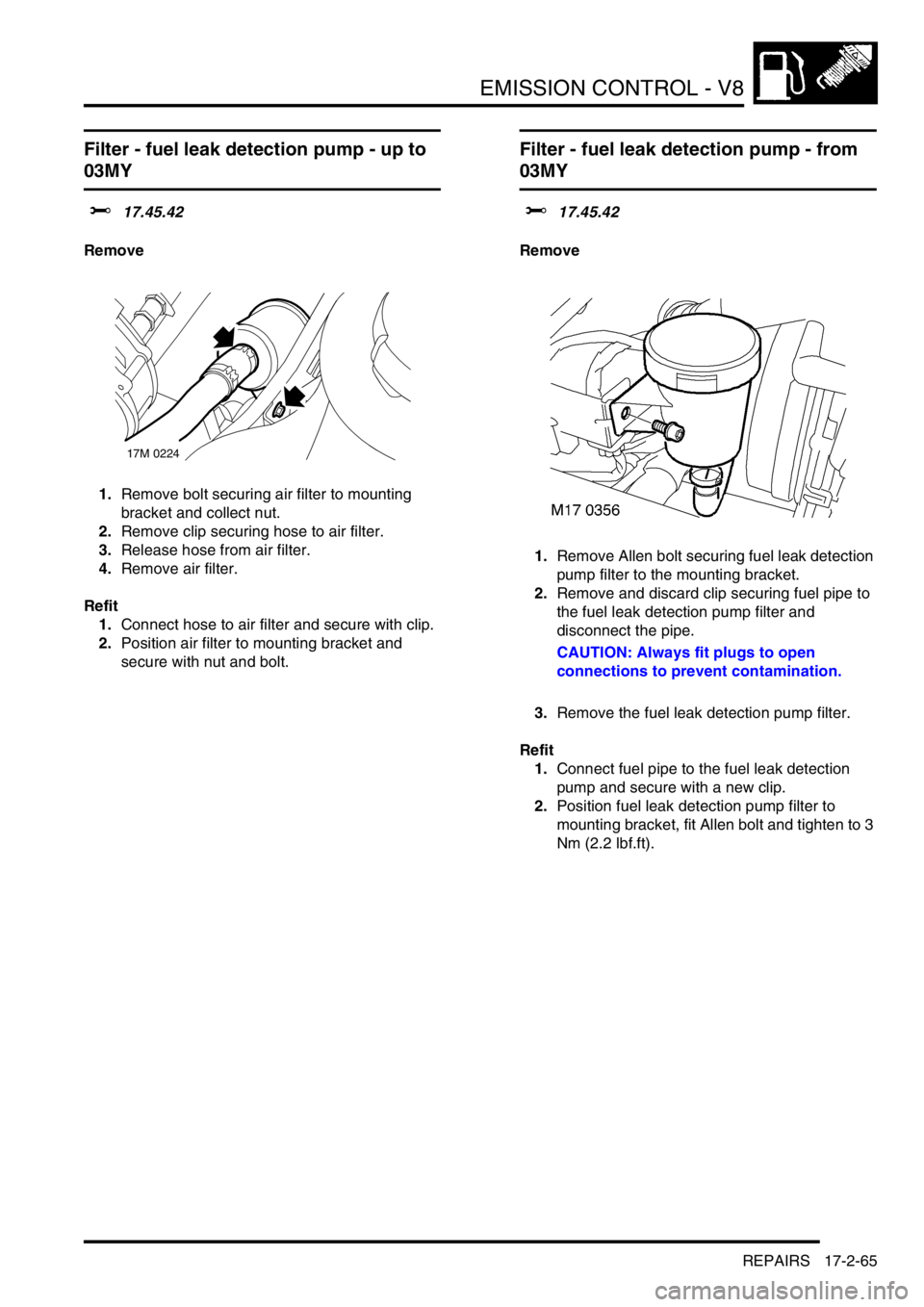
Filter - fuel leak detection pump - up to
03MY
$% 17.45.42
Remove
1.Remove bolt securing air filter to mounting
bracket and collect nut.
2.Remove clip securing hose to air filter.
3.Release hose from air filter.
4.Remove air filter.
Refit
1.Connect hose to air filter and secure with clip.
2.Position air filter to mounting bracket and
secure with nut and bolt.
Filter - fuel leak detection pump - from
03MY
$% 17.45.42
Remove
1.Remove Allen bolt securing fuel leak detection
pump filter to the mounting bracket.
2.Remove and discard clip securing fuel pipe to
the fuel leak detection pump filter and
disconnect the pipe.
CAUTION: Always fit plugs to open
connections to prevent contamination.
3.Remove the fuel leak detection pump filter.
Refit
1.Connect fuel pipe to the fuel leak detection
pump and secure with a new clip.
2.Position fuel leak detection pump filter to
mounting bracket, fit Allen bolt and tighten to 3
Nm (2.2 lbf.ft).
17M 0224
Page 326 of 1529
ENGINE MANAGEMENT SYSTEM - V8
DESCRIPTION AND OPERATION 18-2-27
There are two types of IAT sensor diagnostic checks:
lThe IAT sensor signal is less than the minimum threshold – the engine has to have been running for longer than
180 seconds, and idle speed control must have been operational for longer than 10 seconds. No fuel cut off is
active. The IAT sensor signal must be less than -35°C (-31°F) for longer than 200 ms.
lThe IAT sensor signal is greater than the maximum threshold – the ECM has to be powered up (engine does not
need to be running), and the signal must be greater than 140°C (284°F) for longer than 200 ms.
If the IAT sensor fails the following fault codes will be produced and can be retrieved by TestBook:
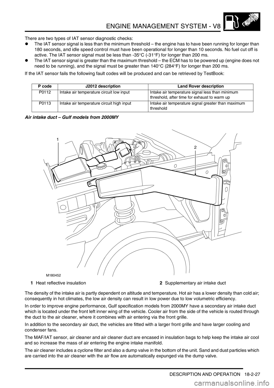
Air intake duct – Gulf models from 2000MY
1Heat reflective insulation2Supplementary air intake duct
The density of the intake air is partly dependent on altitude and temperature. Hot air has a lower density than cold air;
consequently in hot climates, the low air density can result in low power due to low volumetric efficiency.
In order to improve engine performance, Gulf specification models from 2000MY have a secondary air intake duct
which is located under the front left inner wing of the vehicle. Cooler air from the side of the vehicle is routed through
the duct to the air cleaner, where it combines with air entering via the front grille.
In addition to the secondary air duct, the vehicles are fitted with a larger front grille and have larger cooling and
condenser fans.
The MAF/IAT sensor, air cleaner and air cleaner duct are encased in insulation bags to help keep the intake air cool
and so increase the mass of air entering the engine intake manifold.
The air cleaner includes a cyclone filter and also a dump valve in the bottom of the unit. Sand and dust particles which
are carried into the air cleaner with the air flow are automatically expunged via the dump valve.
P code J2012 description Land Rover description
P0112 Intake air temperature circuit low input Intake air temperature signal less than minimum
threshold, after time for exhaust to warm up
P0113 Intake air temperature circuit high input Intake air temperature signal greater than maximum
threshold
M180452
1
2
Page 327 of 1529

ENGINE MANAGEMENT SYSTEM - V8
18-2-28 DESCRIPTION AND OPERATION
Throttle Position (TP) sensor (C0175)
The TP sensor is located on the throttle body assembly in the engine compartment. The ECM is able to determine the
position of the throttle plate and the rate of change of its angle. The ECM processes the signal received from the TP
sensor.
The TP sensor consists of a resistance track and a sliding contact connected to the throttle plate assembly. As the
throttle is opened and closed the sliding contact moves along the resistance track to change the output voltage of the
sensor. The ECM determines throttle plate position by processing this output voltage. The connection of the sensor
to the throttle plate assembly is via a shaft.
The ECM is able to determine the closed throttle position, this enables the TP sensor to be fitted without the need for
prior adjustment. The TP sensor signal has input into the ECM's fuelling strategy and also to determine closed throttle
position for idle speed control. The TP sensor also supplies the ECM with information to enable the overrun fuel cut
off strategy to be implemented. When the ECM receives closed throttle information from the TP sensor it closes the
injectors for the duration of the closed throttle time.
The TP sensor signal is also used by the Electronic Automatic Transmission (EAT) ECU to determine the correct point
for gear shifts and acceleration kickdown. The ECM also supplies the SLABS ECU with this TP sensor information as
a PWM signal.
Input/Output
The TP sensor has electrical input and output. Input is a 5 volt supply via pin 10 of connector C0636 of the ECM. The
signal output is via pin 24 of connector C0636 and is a varying voltage, less than 0.5V (closed throttle) and greater
than 4.5V (wide open throttle) depending on throttle plate position. The TP sensor earth is via pin 25 of connector
C0636 of the ECM, this acts as a screen to protect the integrity of the TP sensor signal.
The connector and sensor terminals are gold plated for corrosion and temperature resistance, care must be exercised
while probing the connector and sensor terminals.
If the TP sensor signal fails, the ECM uses a default value derived from engine load and speed.
The TP sensor can fail the following ways or supply incorrect signal:
lSensor open circuit.
lShort circuit to vehicle supply.
lShort circuit to vehicle earth.
lSignal out of parameters.
lBlocked air filter (load monitoring, ratio of the TP sensor to air flow).
lRestriction in air inlet (load monitoring, ratio of the TP sensor to air flow).
lVacuum leak
Page 398 of 1529

FUEL DELIVERY SYSTEM - V8
DESCRIPTION AND OPERATION 19-2-1
FUEL DELIVERY SYST EM - V8 DESCRIPTION AND OPERAT ION
Fuel delivery system
1Fuel pressure regulator (hidden)
2Schraeder valve
3Fuel rail
4Injectors
5Engine block6Fuel feed pipe
7Coarse filter
8Fine filter
9Fuel pump and fuel gauge sender assembly
Page 403 of 1529
FUEL DELIVERY SYSTEM - V8
19-2-6 DESCRIPTION AND OPERATION
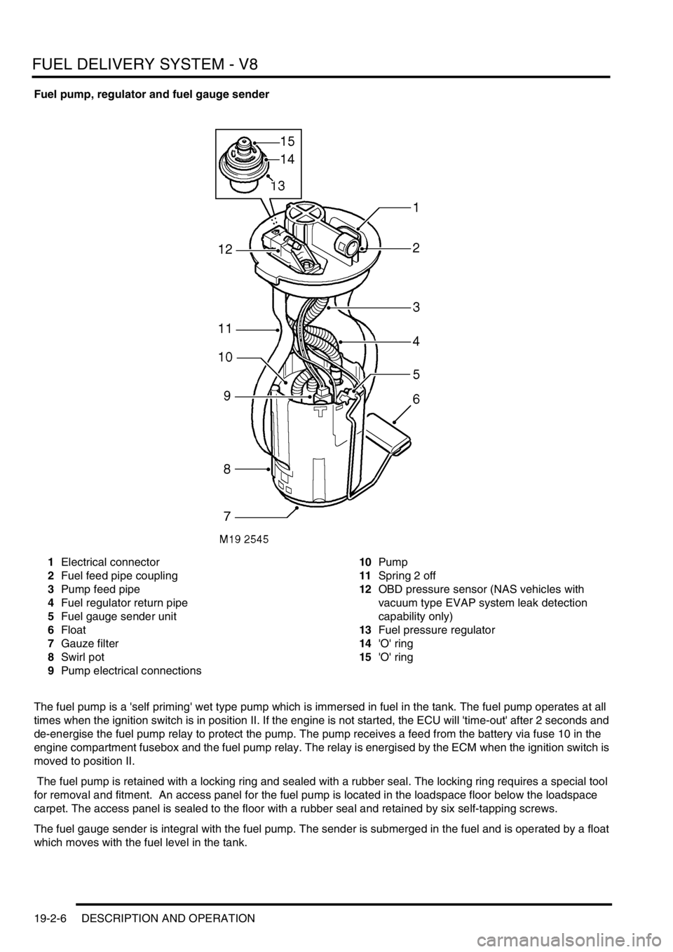
Fuel pump, regulator and fuel gauge sender
1Electrical connector
2Fuel feed pipe coupling
3Pump feed pipe
4Fuel regulator return pipe
5Fuel gauge sender unit
6Float
7Gauze filter
8Swirl pot
9Pump electrical connections10Pump
11Spring 2 off
12OBD pressure sensor (NAS vehicles with
vacuum type EVAP system leak detection
capability only)
13Fuel pressure regulator
14'O' ring
15'O' ring
The fuel pump is a 'self priming' wet type pump which is immersed in fuel in the tank. The fuel pump operates at all
times when the ignition switch is in position II. If the engine is not started, the ECU will 'time-out' after 2 seconds and
de-energise the fuel pump relay to protect the pump. The pump receives a feed from the battery via fuse 10 in the
engine compartment fusebox and the fuel pump relay. The relay is energised by the ECM when the ignition switch is
moved to position II.
The fuel pump is retained with a locking ring and sealed with a rubber seal. The locking ring requires a special tool
for removal and fitment. An access panel for the fuel pump is located in the loadspace floor below the loadspace
carpet. The access panel is sealed to the floor with a rubber seal and retained by six self-tapping screws.
The fuel gauge sender is integral with the fuel pump. The sender is submerged in the fuel and is operated by a float
which moves with the fuel level in the tank.
Page 404 of 1529

FUEL DELIVERY SYSTEM - V8
DESCRIPTION AND OPERATION 19-2-7
Fuel pump
The fuel pump assembly comprises a top cover which locates the fuel pressure regulator, electrical connector and
fuel pipe coupling. The top cover is attached to a plastic cup shaped housing by two metal springs. The housing
locates the pump and the fuel gauge sender unit.
The lower part of the housing is the swirl pot, which maintains a constant fuel level at the fuel pick-up. A feed pipe
from the pump to the coupling connection and a return pipe from the regulator connect between the top cover and the
housing.
A coarse filter is attached to the base of the housing and prevents the ingress of large contaminants into the swirl pot.
A gauze filter prevents particles entering the fuel pump.
Surrounding the pump is a large fine paper filter element which further protects the fuel pressure regulator, engine
and injectors from particulate contamination. The paper filter is not a serviceable item and removes the requirement
for an external in-line filter.
A non-return valve is located in the base of the housing. When the fuel tank is full, fuel pressure keeps the valve lifted
from its seat allowing fuel to flow into the swirl pot. As the tank level reduces, the fuel pressure in the tank reduces
causing the valve to close. When the valve is closed fuel is retained in the swirl pot, ensuring that the swirl pot remains
full and maintains a constant supply to the fuel pump.
A four pin electrical connector is located on the top cover of the pump and provides power feed and return for fuel
pump and fuel gauge rotary potentiometer operation. A single quick release coupling connects the fuel feed pipe to
the outer top surface of the pump.
Two metal springs are attached to the top cover and the housing of the pump. When the pump is installed it seats on
the lower surface inside the tank. The springs exert a downward pressure on the pump and ensure that the pump is
located positively at the bottom of the fuel tank.
The fuel pump has a maximum current draw of 6.5 A at 12.5 V.
On NAS vehicles with vacuum type EVAP system leak detection capability only, the fuel pump top cover is fitted with
an On Board Diagnostics (OBD) pressure sensor. This sensor has a three pin electrical connector which provides a
connection between the sensor and the ECM. The sensor is sealed in the top cover with an 'O' ring and secured with
a clip. The sensor monitors tank pressure during OBD tests of the fuel evaporation system integrity. A hose is
connected to the sensor and is routed across the top of the fuel tank and terminates at the top of the fuel filler tube.
The pipe is open to atmosphere and provides atmospheric pressure for the sensor operation.
+ ENGINE MANAGEMENT SYSTEM - V8, DESCRIPTION AND OPERATION, Description - engine
management.
Fuel pressure regulator
The fuel pressure regulator is located in the underside of the top cover. The regulator is sealed with two 'O' rings and
retained with a clip.
The regulator is connected to the fuel feed pipe at the top of the pump housing and maintains the fuel pump delivery
pressure to 3.5 bar (50 lbf.in
2). When the fuel delivery pressure exceeds 3.5 bar (50 lbf.in2), the regulator opens and
relieves excess pressure back to the swirl pot via a return pipe. The regulator ensures that the fuel rails and injectors
are supplied with a constant pressure.
The fuel pump delivery pressure and pressure regulator operating pressure can be checked using a Schraeder type
valve located at the rear of the engine on the fuel rail. The valve allows the pump delivery pressure to be measured
using a suitable gauge and an adaptor and hose which are special tools.
Page 406 of 1529
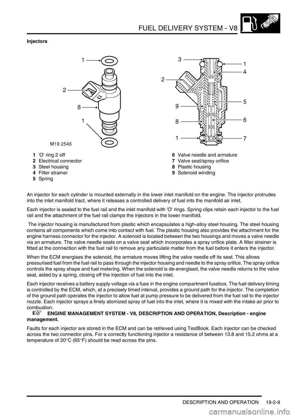
FUEL DELIVERY SYSTEM - V8
DESCRIPTION AND OPERATION 19-2-9
Injectors
1'O' ring 2 off
2Electrical connector
3Steel housing
4Filter strainer
5Spring6Valve needle and armature
7Valve seat/spray orifice
8Plastic housing
9Solenoid winding
An injector for each cylinder is mounted externally in the lower inlet manifold on the engine. The injector protrudes
into the inlet manifold tract, where it releases a controlled delivery of fuel into the manifold air inlet.
Each injector is sealed to the fuel rail and the inlet manifold with 'O' rings. Spring clips retain each injector to the fuel
rail and the attachment of the fuel rail clamps the injectors in the lower manifold.
The injector housing is manufactured from plastic which encapsulates a high-alloy steel housing. The steel housing
contains all components which come into contact with fuel. The plastic housing also provides the attachment for the
engine harness connector for the injector. A solenoid is located between the two housings and moves a valve needle
via an armature. The valve needle seats on a valve seat which incorporates a spray orifice plate. A filter strainer is
fitted at the connection with the fuel rail to remove any particulate matter from the fuel before it enters the injector.
When the ECM energises the solenoid, the armature moves lifting the valve needle off its seat. This allows
pressurised fuel from the fuel rail to pass through the injector housing and needle to the spray orifice. The spray orifice
controls the spray shape and fuel metering. When the solenoid is de-energised, the valve needle returns to the valve
seat, aided by a spring, closing off the injection of fuel into the inlet.
Each injector receives a battery supply voltage via a fuse in the engine compartment fusebox. The fuel delivery timing
is controlled by the ECM, which, at a precisely timed interval, provides a ground path for the injector. The completion
of the ground path operates the injector to allow fuel at pump pressure to be delivered from the fuel rail to the injector
nozzle. Each injector sprays a finely atomized spray of fuel into the inlet, where it is mixed with the intake air prior to
combustion.
+ ENGINE MANAGEMENT SYSTEM - V8, DESCRIPTION AND OPERATION, Description - engine
management.
Faults for each injector are stored in the ECM and can be retrieved using TestBook. Each injector can be checked
across the two connector pins. For a correctly functioning injector a resistance of between 13.8 and 15.2 ohms at a
temperature of 20°C (65°F) should be read across the pins.
Page 859 of 1529

BRAKES
70-6 DESCRIPTION AND OPERATION
Brake servo assembly
The brake servo assembly provides power assistance to reduce the pedal load when braking. If the brake servo
assembly fails, the hydraulic system still functions but will require greater brake pedal effort due to the lack of vacuum
assistance.
Two integral tie bolts attach the brake servo assembly to the pedal and bracket assembly on the engine bulkhead.
The master cylinder assembly is attached to the forward ends of the tie bolts.
The brake servo assembly consists of a circular housing which contains two diaphragms, a central plate, a control
valve assembly, input and output push rods and a filter. The input push rod is connected to the brake pedal. The output
push rod locates in the primary piston of the master cylinder. A protective gaiter is installed on the control valve
assembly where it extends from the rear of the housing. A non return valve, installed in a port in the front face of the
housing, is connected to a vacuum line from the engine.
The control valve assembly consists of a valve body containing a valve, a piston, a valve spring and an input rod
spring. The valve controls a vacuum port in the valve body. The piston controls an air inlet port between the valve and
the piston. A reaction disc and a ratio disc separate the piston from the output push rod. A guide tube on the front of
the valve body is attached to the front diaphragm and supported in a bush in the central plate. A return spring locates
in the open end of the guide tube.
The two diaphragms and the central plate separate the interior of the housing into four sealed chambers. The
chambers at the front of the diaphragms are connected together through fixed passages in the valve assembly. The
chambers at the rear of the diaphragms are connected together through the interior of minor diaphragms on the tie
bolts.
Brakes off
With the brake pedal released, the piston in the control valve assembly positions the valve so that the vacuum port is
open and the two pairs of chambers are connected together. When the engine is running air is evacuated through the
vacuum line and non return valve, creating a partial vacuum in all four chambers. When the engine stops, the non
return valve closes to maintain the partial vacuum and, on V8 models, prevent fuel vapour entering the brake servo.