check engine light LAND ROVER DISCOVERY 1999 Workshop Manual
[x] Cancel search | Manufacturer: LAND ROVER, Model Year: 1999, Model line: DISCOVERY, Model: LAND ROVER DISCOVERY 1999Pages: 1529, PDF Size: 34.8 MB
Page 39 of 1529

GENERAL INFORMATION
03-4
Spill kits
Special materials are available to absorb a number of
different substances. They can be in granular form,
ready to use and bought in convenient containers for
storage. Disposal of used spill-absorbing material is
dealt with in 'Waste Management' section.
Land contamination
Oils, fuels and solvents etc. can contaminate any soil
that they are allowed to contact. Such materials
should never be disposed of by pouring onto soil and
every precaution must be taken to prevent spillage
reaching soil. Waste materials stored on open
ground could also leak, or have polluting substances
washed off them that would contaminate the land.
Always store these materials in suitable skips or
other similarly robust containers.
Checklist
Always adhere to the following.
lDon't pour or spill anything onto the soil or bare
ground;
ldon't store waste materials on bare ground, see
'Spillage prevention' list.
Legal compliance
Some sites may have a discharge consent for
effluent discharge to the foul drain for a car wash etc.
It is important to know what materials are allowed in
the drain and to check the results of any monitoring
carried out by the Water Company.
Where paint-spraying operations are carried out it
may be necessary to apply to the Local Authority for
an air emissions licence to operate the plant. If such
a licence is in operation, additional precautions will
be necessary to comply with the requirements, and
the results of any air quality monitoring must be
checked regularly.
Checklist
Always adhere to the following.
lKnow what legal consents and licences apply to
the operations;
lcheck that the emissions and discharges
comply with legal requirements.
Local issues
A number of environmental issues will be of
particular concern to residents and other neighbours
close to the site. The sensitivity of these issues will
depend on the proximity of the site and the layout
and amount of activity carried on at the site.
Noise is a major concern and therefore
consideration should be given to the time spent
carrying out noisy activities and the location of those
activities that can cause excessive noise. Car alarm testing, panel beating, hammering and
other such noisy activities should, whenever
possible, be carried out indoors with doors and
windows shut or as far away from houses as
possible.
Running vehicle engines may be an outside activity
which could cause nuisance to neighbours because
of both noise and smell.
Be sensitive to the time of day when these activities
are carried out and minimise the time of the noisy
operation, particularly in the early morning and late
evening.
Another local concern will be the smell from the
various materials used. Using less solvent, paint
and petrol could help prevent this annoyance.
Local residents and other business users will also be
concerned about traffic congestion, noise and
exhaust fumes, be sensitive to these concerns and
try to minimise inconvenience from deliveries,
customers and servicing operations.
Checklist
Always adhere to the following.
lIdentify where the neighbours who are likely to
be affected are situated;
lminimise noise, smells and traffic nuisance;
lprevent litter by putting waste in the correct
containers;
lhave waste skips emptied regularly.
Use of resource
Another environmental concern is the waste of
materials and energy that can occur in day to day
activities.
Electricity for heating, lighting and compressed air
uses resources and releases pollution during its
generation.
Fuel used for heating, running cars or vans and
mobile plant is another limited resource which
consumes large amounts of energy during its
extraction and refining processes.
Water has to be cleaned, piped to site and disposed
of; all of which creates more potential pollution.
Oil, spares, paint etc., have all produced pollution in
the process of manufacture and they become a
waste disposal problem if discarded.
Page 40 of 1529

GENERAL INFORMATION
03-5
Checklist
Always adhere to the following.
Electricity and heating:
lkeep doors and windows closed in the winter;
lswitch off machinery or lights when not needed;
luse energy efficient heating systems;
lswitch off computers and photocopiers when
not needed.
Fuel:
ldon't run engines unnecessarily;
lthink about whether journeys are necessary and
drive to conserve fuel.
Water:
ldon't leave taps and hose pipes running;
lmend leaks quickly, don't be wasteful.
Compressed air:
ldon't leave valves open;
lmend leaks quickly;
ldon't leave the compressor running when not
needed.
Use of environmentally damaging materials:
lcheck whether a less toxic material is available.
Handling and storage of materials:
lhave the correct facilities available for handling
liquids to prevent spillage and wastage as listed
above;
lprovide suitable locations for storage to prevent
frost damage or other deterioration.
Waste Management
One of the major ways that pollution can be reduced
is by the careful handling, storage and disposal of all
waste materials that occur on sites. Legislation
makes it illegal to dispose of waste materials other
than to licensed waste carriers and disposal sites.
This means that it is necessary to not only know what
the waste materials are, but also to have the
necessary documentation and licenses.
Handling and storage of waste
Ensure that waste materials are not poured down the
drain or onto soils. They should be stored in such a
way as to prevent the escape of the material to land,
water or air.
They must also be segregated into different types of
waste e.g. oil, metals, batteries, used vehicle
components. This will prevent any reaction between
different materials and assist in disposal.Disposal of waste
Disposal of waste materials must only be to waste
carriers who are licensed to carry those particular
waste materials and all the necessary
documentation must be completed. The waste
carrier is responsible for ensuring that the waste is
taken to the correct disposal sites.
Dispose of waste in accordance with the following
guidelines.
lFuel, hydraulic fluid, anti-freeze and oil: keep
separate and dispose of to specialist contractor.
lRefrigerant: collect in specialist equipment and
reuse.
lDetergents: safe to pour down the foul drain if
diluted.
lPaint, thinners: keep separate and dispose of
to specialist contractor.
lComponents: send back to supplier for
refurbishment, or disassemble and reuse any
suitable parts. Dispose of the remainder in
ordinary waste.
lSmall parts: reuse any suitable parts, dispose
of the remainder in ordinary waste.
lMetals: can be sold if kept separate from
general waste.
lTyres: keep separate and dispose of to
specialist contractor.
lPackaging: compact as much as possible and
dispose of in ordinary waste.
lAsbestos-containing: keep separate and
dispose of to specialist contractor.
lOily and fuel wastes (e.g. rags, used spill kit
material): keep separate and dispose of to
specialist contractor.
lAir filters: keep separate and dispose of to
specialist contractor.
lRubber/plastics: dispose of in ordinary waste.
lHoses: dispose of in ordinary waste.
lBatteries: keep separate and dispose of to
specialist contractor.
lAirbags - explosives: keep separate and
dispose of to specialist contractor.
lElectrical components: send back to supplier
for refurbishment, or disassemble and reuse
any suitable parts. Dispose of the remainder in
ordinary waste.
lElectronic components: send back to supplier
for refurbishment, or disassemble and reuse
any suitable parts. Dispose of the remainder in
ordinary waste.
lCatalysts: can be sold if kept separate from
general waste
lUsed spill-absorbing material: keep separate
and dispose of to specialist contractor.
lOffice waste: recycle paper and toner and ink
cartridges, dispose of the remainder in ordinary
waste.
Page 50 of 1529
GENERAL INFORMATION
03-15
Hose clips
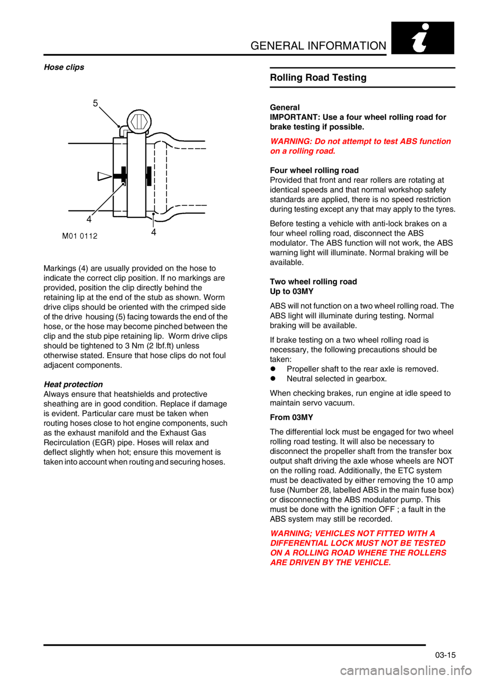
Markings (4) are usually provided on the hose to
indicate the correct clip position. If no markings are
provided, position the clip directly behind the
retaining lip at the end of the stub as shown. Worm
drive clips should be oriented with the crimped side
of the drive housing (5) facing towards the end of the
hose, or the hose may become pinched between the
clip and the stub pipe retaining lip. Worm drive clips
should be tightened to 3 Nm (2 lbf.ft) unless
otherwise stated. Ensure that hose clips do not foul
adjacent components.
Heat protection
Always ensure that heatshields and protective
sheathing are in good condition. Replace if damage
is evident. Particular care must be taken when
routing hoses close to hot engine components, such
as the exhaust manifold and the Exhaust Gas
Recirculation (EGR) pipe. Hoses will relax and
deflect slightly when hot; ensure this movement is
taken into account when routing and securing hoses.
Rolling Road Testing
General
IMPORTANT: Use a four wheel rolling road for
brake testing if possible.
WARNING: Do not attempt to test ABS function
on a rolling road.
Four wheel rolling road
Provided that front and rear rollers are rotating at
identical speeds and that normal workshop safety
standards are applied, there is no speed restriction
during testing except any that may apply to the tyres.
Before testing a vehicle with anti-lock brakes on a
four wheel rolling road, disconnect the ABS
modulator. The ABS function will not work, the ABS
warning light will illuminate. Normal braking will be
available.
Two wheel rolling road
Up to 03MY
ABS will not function on a two wheel rolling road. The
ABS light will illuminate during testing. Normal
braking will be available.
If brake testing on a two wheel rolling road is
necessary, the following precautions should be
taken:
lPropeller shaft to the rear axle is removed.
lNeutral selected in gearbox.
When checking brakes, run engine at idle speed to
maintain servo vacuum.
From 03MY
The differential lock must be engaged for two wheel
rolling road testing. It will also be necessary to
disconnect the propeller shaft from the transfer box
output shaft driving the axle whose wheels are NOT
on the rolling road. Additionally, the ETC system
must be deactivated by either removing the 10 amp
fuse (Number 28, labelled ABS in the main fuse box)
or disconnecting the ABS modulator pump. This
must be done with the ignition OFF ; a fault in the
ABS system may still be recorded.
WARNING; VEHICLES NOT FITTED WITH A
DIFFERENTIAL LOCK MUST NOT BE TESTED
ON A ROLLING ROAD WHERE THE ROLLERS
ARE DRIVEN BY THE VEHICLE.
Page 62 of 1529
GENERAL INFORMATION
03-27
Body Repairs
General
Body shells are of welded construction and bolted to
a chassis frame. Front and rear sections of the shell
are designed as 'energy absorbing' zones. This
means they are designed to deform progressively
when subjected to impact in order to minimise the
likelihood of injury to vehicle occupants.
It is essential that design dimensions and strength
are restored in accident rectification. It is important
that neither structural weakness nor excessive local
stiffness are introduced into the vehicle during body
repair.
Repairs usually involve a combination of operations
ranging from straightening procedures to renewal of
individual panels or panel assemblies. The repairer
will determine the repair method and this decision will
take into account a balance of economics between
labour and material costs and the availability of repair
facilities in both equipment and skills. It may also
involve considerations of the vehicles' downtime,
replacement vehicle availability and repair turn-
around time.
It is expected that a repairer will select the best and
most economic repair method possible, making use
of the facilities available. The instructions given are
intended to assist a skilled body repairer by
expanding approved procedures for panel
replacement. The objective is to restore the vehicle
to a safe running condition by carrying out a repair
which is as close as is feasible to original standard.
The results should not advertise to the experienced
eye that the vehicle has been damaged, although the
repair might not be identical in all respects to the
original factory build. Commercial bodyshop repair
facilities cannot always duplicate methods of
construction used during production.
Operations covered in this Manual do not include
reference to testing the vehicle after repair. It is
essential that work is inspected and suspension
geometry checked after completion. Where
necessary a road test of the vehicle should be carried
out, particularly where safety-related items are
concerned.
Where major units have been disconnected or
removed it is necessary to ensure that fluid levels are
checked and topped up where necessary. It is also
necessary to ensure that the repaired vehicle is in a
roadworthy condition in respect of tyre pressures,
lights, washer fluid etc. Body repairs often involve the removal of mechanical
and electrical units and associated wiring. Where
necessary, refer to the relevant section of the
Workshop Manual for removal and refitting
instructions.
Taking into consideration the differences in body
styles, suspension systems and engine and
transmission layouts, the location of the following
components as applicable to a particular vehicle is
critical:
lFront suspension upper damper mountings on
RH and LH chassis longitudinals.
lFront suspension or sub frame mountings.
lEngine mountings on RH and LH chassis
longitudinals.
lRear suspension upper damper mountings on
RH and LH chassis longitudinals.
lRear suspension mountings or lower pivots.
Additional points which can be used to check
alignment and assembly are:
lInner holes in cross member - side - main floor.
lHoles in front bulkhead.
lHoles in rear longitudinals.
lHoles in rear lower panels.
Apertures for windscreen, rear screen, bonnet and
doors can be measured and checked using the
dimensional information provided and also by
offering up an undamaged component as a gauge.
Straightening
Whenever possible, structural members should be
cold straightened under tension. Do not attempt to
straighten with a single pull but rework the damaged
area using a series of pulls, releasing tension
between each stage and using the opportunity to
check alignment.
Body jig
Unless damage is limited to cosmetic panels, all
repair work to body members must be carried out on
a body jig, to ensure that impact damage has not
spread into more remote parts of the structure.
Mounting on a jig will also ensure that the
straightening and panel replacement procedures do
not cause further distortion.
If original dimensions cannot be satisfactorily
restored by these methods, damaged structural
members should be replaced. Damaged areas
should be cut away using a high speed saw, NOT an
oxy-acetylene torch.
As a rule, body dimensions are symmetrical about
the centre line. A good initial check for distortion is
therefore to measure diagonally and to investigate
apparent differences in dimensions.
Page 170 of 1529
ENGINE - V8
REPAIRS 12-2-15
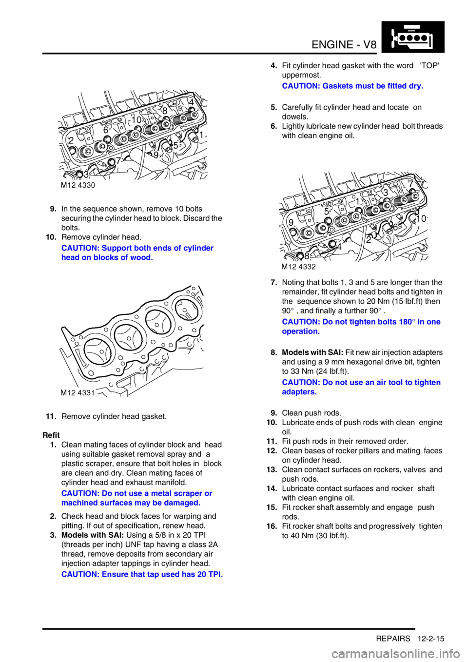
9.In the sequence shown, remove 10 bolts
securing the cylinder head to block. Discard the
bolts.
10.Remove cylinder head.
CAUTION: Support both ends of cylinder
head on blocks of wood.
11.Remove cylinder head gasket.
Refit
1.Clean mating faces of cylinder block and head
using suitable gasket removal spray and a
plastic scraper, ensure that bolt holes in block
are clean and dry. Clean mating faces of
cylinder head and exhaust manifold.
CAUTION: Do not use a metal scraper or
machined surfaces may be damaged.
2.Check head and block faces for warping and
pitting. If out of specification, renew head.
3. Models with SAI: Using a 5/8 in x 20 TPI
(threads per inch) UNF tap having a class 2A
thread, remove deposits from secondary air
injection adapter tappings in cylinder head.
CAUTION: Ensure that tap used has 20 TPI.4.Fit cylinder head gasket with the word 'TOP'
uppermost.
CAUTION: Gaskets must be fitted dry.
5.Carefully fit cylinder head and locate on
dowels.
6.Lightly lubricate new cylinder head bolt threads
with clean engine oil.
7.Noting that bolts 1, 3 and 5 are longer than the
remainder, fit cylinder head bolts and tighten in
the sequence shown to 20 Nm (15 lbf.ft) then
90° , and finally a further 90° .
CAUTION: Do not tighten bolts 180° in one
operation.
8. Models with SAI: Fit new air injection adapters
and using a 9 mm hexagonal drive bit, tighten
to 33 Nm (24 lbf.ft).
CAUTION: Do not use an air tool to tighten
adapters.
9.Clean push rods.
10.Lubricate ends of push rods with clean engine
oil.
11.Fit push rods in their removed order.
12.Clean bases of rocker pillars and mating faces
on cylinder head.
13.Clean contact surfaces on rockers, valves and
push rods.
14.Lubricate contact surfaces and rocker shaft
with clean engine oil.
15.Fit rocker shaft assembly and engage push
rods.
16.Fit rocker shaft bolts and progressively tighten
to 40 Nm (30 lbf.ft).
Page 173 of 1529
ENGINE - V8
12-2-18 REPAIRS
13.Remove cylinder head gasket.
Refit
1.Clean mating faces of cylinder block and head
using suitable gasket removal spray and a
plastic scraper, ensure that bolt holes in block
are clean and dry. Clean mating faces of
cylinder head and exhaust manifold.
CAUTION: Do not use a metal scraper or
machined surfaces may be damaged.
2.Check head and block faces for warping and
pitting. If out of specification, renew head.
3. Models with SAI: Using a 5/8 in x 20 TPI
(threads per inch) UNF tap having a class 2A
thread, remove deposits from secondary air
injection adapter tappings in cylinder head.
CAUTION: Ensure that tap used has 20 TPI.
4.Fit cylinder head gasket with the word 'TOP'
uppermost.
CAUTION: Gasket must be fitted dry.
5.Carefully fit cylinder head and locate on
dowels.
6.Lightly lubricate new cylinder head bolt threads
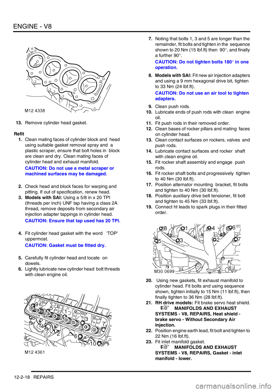
with clean engine oil. 7.Noting that bolts 1, 3 and 5 are longer than the
remainder, fit bolts and tighten in the sequence
shown to 20 Nm (15 lbf.ft) then 90°, and finally
a further 90°.
CAUTION: Do not tighten bolts 180° in one
operation.
8. Models with SAI: Fit new air injection adapters
and using a 9 mm hexagonal drive bit, tighten
to 33 Nm (24 lbf.ft).
CAUTION: Do not use an air tool to tighten
adapters.
9.Clean push rods.
10.Lubricate ends of push rods with clean engine
oil.
11.Fit push rods in their removed order.
12.Clean bases of rocker pillars and mating faces
on cylinder head.
13.Clean contact surfaces on rockers, valves and
push rods.
14.Lubricate contact surfaces and rocker shaft
with clean engine oil.
15.Fit rocker shaft assembly and engage push
rods.
16.Fit rocker shaft bolts and progressively tighten
to 40 Nm (30 lbf.ft).
17.Position alternator mounting bracket, fit bolts
and tighten to 40 Nm (30 lbf.ft).
18.Position auxiliary drive belt tensioner, fit bolt
and tighten to 45 Nm (33 lbf.ft).
19.Connect ht leads to spark plugs in their fitted
order.
20. Using new gaskets, fit exhaust manifold to
cylinder head. Fit bolts and using sequence
shown, tighten initially to 15 Nm (11 lbf.ft), then
finally tighten to 36 Nm (28 lbf.ft).
21. RH drive models: Fit brake servo heat shield.
+ MANIFOLDS AND EXHAUST
SYSTEMS - V8, REPAIRS, Heat shield -
brake servo - Without Secondary Air
Injection.
22.Position engine earth lead, fit bolt and tighten to
22 Nm (16 lbf.ft).
23.Fit inlet manifold gasket.
+ MANIFOLDS AND EXHAUST
SYSTEMS - V8, REPAIRS, Gasket - inlet
manifold - lower.
Page 217 of 1529
ENGINE - V8
12-2-62 OVERHAUL
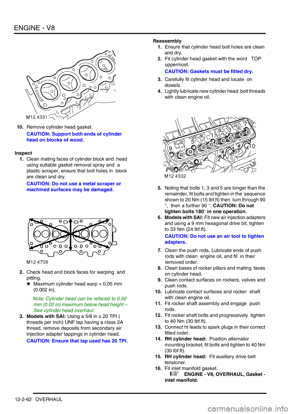
10.Remove cylinder head gasket.
CAUTION: Support both ends of cylinder
head on blocks of wood.
Inspect
1.Clean mating faces of cylinder block and head
using suitable gasket removal spray and a
plastic scraper, ensure that bolt holes in block
are clean and dry.
CAUTION: Do not use a metal scraper or
machined surfaces may be damaged.
2.Check head and block faces for warping and
pitting.
lMaximum cylinder head warp = 0.05 mm
(0.002 in).
Note: Cylinder head can be refaced to 0.50
mm (0.02 in) maximum below head height –
See cylinder head overhaul.
3. Models with SAI: Using a 5/8 in x 20 TPI (
threads per inch) UNF tap having a class 2A
thread, remove deposits from secondary air
injection adapter tappings in cylinder head.
CAUTION: Ensure that tap used has 20 TPI.Reassembly
1.Ensure that cylinder head bolt holes are clean
and dry.
2.Fit cylinder head gasket with the word TOP
uppermost.
CAUTION: Gaskets must be fitted dry.
3.Carefully fit cylinder head and locate on
dowels.
4.Lightly lubricate new cylinder head bolt threads
with clean engine oil.
5.Noting that bolts 1, 3 and 5 are longer than the
remainder, fit bolts and tighten in the sequence
shown to 20 Nm (15 lbf.ft) then turn through 90
°, then a further 90 °. CAUTION: Do not
tighten bolts 180° in one operation.
6. Models with SAI: Fit new air injection adapters
and using a 9 mm hexagonal drive bit, tighten
to 33 Nm (24 lbf.ft).
CAUTION: Do not use an air tool to tighten
adapters.
7.Clean the push rods, Lubricate ends of push
rods with clean engine oil, and fit in their
removed order.
8.Clean bases of rocker pillars and mating faces
on cylinder head.
9.Clean contact surfaces on rockers, valves and
push rods.
10.Lubricate contact surfaces and rocker shaft
with clean engine oil.
11.Fit rocker shaft assembly and engage push
rods.
12.Fit rocker shaft bolts and progressively tighten
to 40 Nm (30 lbf.ft).
13.Connect ht leads to spark plugs in their correct
fitted order.
14. RH cylinder head: Position alternator
mounting bracket, fit bolts and tighten to 40 Nm
(30 lbf.ft).
15. RH cylinder head: Fit auxiliary drive belt
tensioner.
16.Fit inlet manifold gasket.
+ ENGINE - V8, OVERHAUL, Gasket -
inlet manifold.
Page 222 of 1529
ENGINE - V8
OVERHAUL 12-2-67
35. Check that cutter blades are adjusted so that
middle of blade contacts area of material to be
cut. Use light pressure and only remove the
minimum of material necessary.
36.Clean valve seat and valve.
Reassembly
1.Clean spring caps, collets and valve springs.
2.Lubricate new valve stem oil seal with clean
engine oil and fit seal.
3.Lubricate valve with clean engine oil and fit
valve.
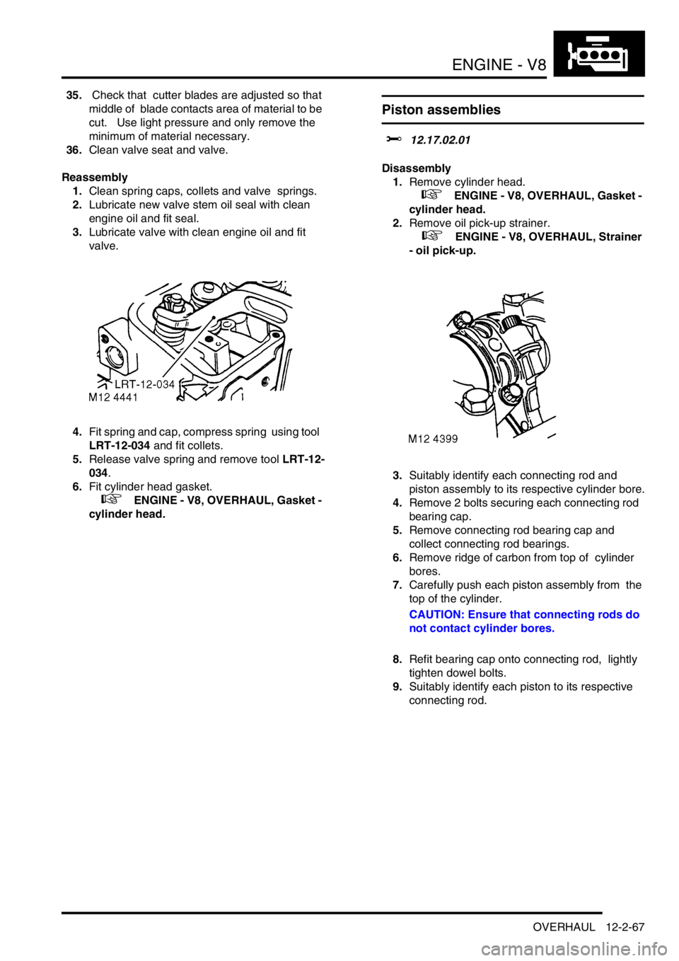
4.Fit spring and cap, compress spring using tool
LRT-12-034 and fit collets.
5.Release valve spring and remove tool LRT-12-
034.
6.Fit cylinder head gasket.
+ ENGINE - V8, OVERHAUL, Gasket -
cylinder head.
Piston assemblies
$% 12.17.02.01
Disassembly
1.Remove cylinder head.
+ ENGINE - V8, OVERHAUL, Gasket -
cylinder head.
2.Remove oil pick-up strainer.
+ ENGINE - V8, OVERHAUL, Strainer
- oil pick-up.
3.Suitably identify each connecting rod and
piston assembly to its respective cylinder bore.
4.Remove 2 bolts securing each connecting rod
bearing cap.
5.Remove connecting rod bearing cap and
collect connecting rod bearings.
6.Remove ridge of carbon from top of cylinder
bores.
7.Carefully push each piston assembly from the
top of the cylinder.
CAUTION: Ensure that connecting rods do
not contact cylinder bores.
8.Refit bearing cap onto connecting rod, lightly
tighten dowel bolts.
9.Suitably identify each piston to its respective
connecting rod.
Page 227 of 1529

ENGINE - V8
12-2-72 OVERHAUL
Bearings - connecting rods
$% 12.17.16.01
Disassembly
1.Remove oil pick up strainer.
+ ENGINE - V8, OVERHAUL, Strainer
- oil pick-up.
2.Suitably mark cylinder reference number on
each connecting rod bearing cap.
3.Remove 2 bolts securing each connecting rod
bearing cap, remove caps and recover
connecting rod bearings.
CAUTION: Keep bearing caps, bearings and
bolts in their fitted order.
4.Push each connecting rod up cylinder bore
until connecting rods are clear of crankshaft
journals.
CAUTION: Ensure that connecting rods do
not contact cylinder bores.
5.Remove bearing shells from each connecting
rod. Inspect
1.Clean crankshaft journals and bearing
locations in connecting rods.
2.Inspect connecting rod bearings for wear and
renew if necessary. Connecting rod bearings
are available in two oversizes.
lConnecting rod bearing 1st oversize = 0.254
mm (0.01 in).
lConnecting rod bearing 2nd oversize =
0.508 mm (0.02 in).
3.Check crankshaft big-end journals for wear and
scoring. Measure for ovality; taking 3
measurements at 120° intervals at each end
and at centre of journals.
lStandard journal = 55.500 to 55.513 mm
(2.20 to 2.22 in).
l1st undersize journal - 0.254 mm (0.01 in) =
55.246 to 55.259 mm (2.17 to 2.18 in).
l2nd undersize journal - 0.508 mm (0.02 in)
= 54.992 to 55.005 mm (2.16 to 2.165 in).
lJournal - max. ovality = 0.040 mm (0.002 in)
Reassembly
1.Clean connecting rod caps.
2.Lubricate connecting rod journals and bearing
shells with clean engine oil.
3.Fit bearing shells to connecting rods and caps.
4.Rotate crankshaft until connecting rod journals
are correctly positioned.
5.Taking care not to displace bearing shells, pull
connecting rods on to crankshaft journals.
6.Check that bearing shells are correctly located
in connecting rod bearing caps.
7.Fit connecting rod bearing caps, ensuring that
they are in their correct fitted order.
NOTE: The rib on the edge of the bearing cap
must face towards the front of engine on the RH
bank of cylinders and towards the rear on the
LH bank.
8.Lightly oil threads of connecting rod bolts. Fit
connecting rod bolts and tighten to 20 Nm (15
lbf.ft) then turn a further 80°.
Page 230 of 1529

ENGINE - V8
OVERHAUL 12-2-75
Reassembly
1.Clean main bearing locations in cylinder block
and bearing caps; ensure bolt holes are clean
and dry.
2.Clean sealant from rear main bearing cap and
mating faces.
3.Fit key to keyway.
4.Check threads of main bearing cap bolts for
damage, renew bolts in pairs.
5.Lubricate grooved main bearing shells with
clean engine oil and fit to their locations in
cylinder block.
NOTE: Ensure that the flanged bearing is fitted
to the centre position.
6.Lubricate crankshaft journals with clean engine
oil.
7.Position crankshaft in cylinder block.
8.Lubricate plain bearing shells with clean
engine oil and fit to main bearing caps.
9.Fit main bearing caps 1 to 4 only at this stage,
ensuring that they are the correct way round
and in their fitted order.
10.Lightly lubricate threads of main bearing cap
bolts with clean engine oil.
11.Fit main bearing cap bolts but do not tighten at
this stage. Do not fit side bolts at this stage.12.Lubricate new cruciform seals with engine oil
and fit to rear main bearing cap.
CAUTION: Do not trim off excess from
cruciform seals at this stage.
13.Apply a 3 mm (0.12 in) wide bead of sealant,
Part No. STC 50550 to bearing cap rear mating
faces on cylinder block.
CAUTION: Ensure sealant does not enter
bolt holes.
14.Carefully fit rear main bearing cap assembly, fit
but do not tighten bolts.
CAUTION: Ensure engine oil does not enter
the side bolt holes in the bearing cap. Do
not trim off excess material from cruciform
seals at this stage.
15.Lubricate 'Dowty' washers with engine oil and
fit to side bolts.
16.Fit but do not tighten side bolts. Rear side
bolts are Allen headed.
17.Using the sequence shown, tighten main
bearing cap bolts as follows:
lInitial torque - all main bearing cap bolts and
side bolts - 13.5 Nm (10 lbf.ft).
lFinal torque - main bearing cap side bolts 11
to 15 - 45 Nm (34 lbf.ft).
lFinal torque - main bearing cap bolts 1 to 8
- 72 Nm (54 lbf.ft).
lFinal torque - main bearing cap bolts 9 and
10 - 92 Nm (68 lbf.ft).
lFinal torque - main bearing cap side bolts 16
to 20 - 45 Nm (34 lbf.ft).
18.Trim off excess material from cruciform seals.