wheel bolts LAND ROVER DISCOVERY 2002 Owner's Manual
[x] Cancel search | Manufacturer: LAND ROVER, Model Year: 2002, Model line: DISCOVERY, Model: LAND ROVER DISCOVERY 2002Pages: 1672, PDF Size: 46.1 MB
Page 295 of 1672

ENGINE - V8
12-2-52 OVERHAUL
Bearing - spigot - crankshaft
$% 12.21.45.01
Disassembly
1.Remove 6 bolts securing clutch cover.
2.Remove clutch cover.
3.Tap a thread in spigot bush to accommodate a
suitable impulse extractor.
4.Fit extractor to bush.
5.Remove bush from crankshaft. Reassembly
1.Clean bush register in rear of crankshaft.
2.Using a suitable drift, fit new bush to crankshaft
so that it is flush with or up to a maximum of 1.6
mm (0.06 in) below the end of the crankshaft.
3.Ream spigot bush to 19.117 + 0.025
− 0.00 mm
(0.75 + 0.001
− 0.00 in) .
4.Remove all traces of swarf on completion.
5.Clean mating faces of flywheel and crankshaft,
dowel and dowel hole.
6.Fit clutch cover to flywheel and tighten bolts by
diagonal slection to 40 Nm (30 lbf.ft).
Page 657 of 1672

CLUTCH - TD5
33-1-6 DESCRIPTION AND OPERATION
Description
General
The clutch system is a diaphragm type clutch operated by a hydraulic cylinder. The drive plate is of the rigid centre
type with no integral damping springs. The flywheel is of the dual mass type with damping springs integral with the
flywheel. The clutch requires no adjustment to compensate for wear.
Hydraulic clutch
The hydraulic clutch comprises a master cylinder, slave cylinder and a hydraulic reservoir. The master and slave
cylinders are connected to each other hydraulically by plastic and metal pipes. The plastic section of the pipe allows
ease of pipe routing and also absorbs engine movements and vibrations.
The master cylinder comprises a body with a central bore. Two ports in the body connect the bore to the hydraulic
feed pipe to the slave cylinder and the fluid reservoir. The bore is also connected to a damper which prevents engine
pulses being transferred hydraulically to the clutch pedal. A piston is fitted in the bore and has an external rod which
is attached to the clutch pedal with a pin. Two coil springs on the clutch pedal reduce the effort required to depress
the pedal.
The master cylinder is mounted on the bulkhead and secured with two bolts. The cylinder is connected to the shared
brake/clutch reservoir on the brake servo by a braided connecting hose.
The slave cylinder is located on the left hand side of the gearbox housing and secured with two bolts. A heat shield
is fitted to protect the underside of the slave cylinder from heat generated from the exhaust system. The slave cylinder
comprises a cylinder with a piston and a rod. A port in the cylinder body provides the attachment for the hydraulic feed
pipe from the master cylinder. A second port is fitted witha bleed nipple used for removing air from the hydraulic
system after servicing. The piston rod locates on a clutch release lever located in the gearbox housing. The rod is
positively retained on the release lever with a clip.
Clutch mechanism
The clutch mechanism comprises a flywheel, drive plate, pressure plate, release lever and a release bearing. The
clutch mechanism is fully enclosed at the rear of the engine by the gearbox housing.
A clutch release bearing sleeve is attached in the gearbox housing with two bolts and located on two dowels. A spigot
with a ball end is formed on the release bearing sleeve and provides amounting and pivot point for the clutch release
lever. A dished pivot washer is located on the ball of the spigot. When the release lever is located on the ball, the pivot
washer seats against the rear face of the release lever. A spring clip is located on the lever and the pivot washer and
secures the lever on the spigot. A small bolt retains the spring clip in position.
The release lever is forked at its inner end and locates on the clutch release bearing carrier. The outer end of the
release lever has a nylon seat which locates the slave cylinder piston rod. A second nylon seat, positioned centrally
on the release lever, locates on the ball spigot of the release bearing sleeve and allows the release lever to pivot freely
around the ball.
The clutch release bearing locates on the clutch release lever and release bearing sleeve. The bearing is retained on
a carrier which has two flats to prevent the carrier rotating on the release lever. A clip retains the release lever on the
carrier. The bearing and carrier are not serviceable individually.
Page 658 of 1672

CLUTCH - TD5
DESCRIPTION AND OPERATION 33-1-7
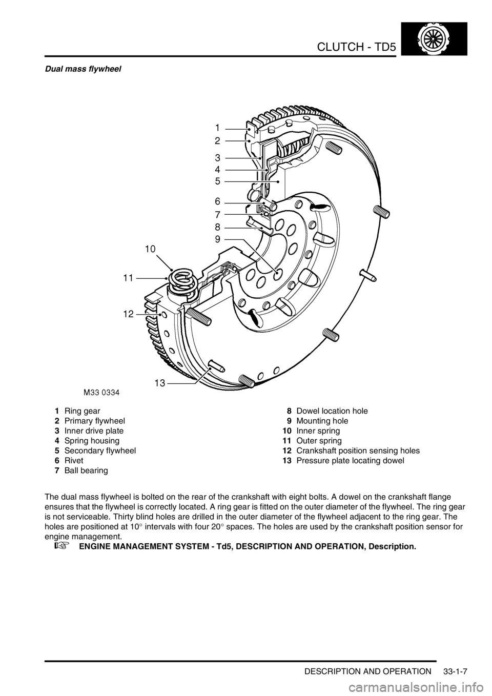
Dual mass flywheel
1Ring gear
2Primary flywheel
3Inner drive plate
4Spring housing
5Secondary flywheel
6Rivet
7Ball bearing8Dowel location hole
9Mounting hole
10Inner spring
11Outer spring
12Crankshaft position sensing holes
13Pressure plate locating dowel
The dual mass flywheel is bolted on the rear of the crankshaft with eight bolts. A dowel on the crankshaft flange
ensures that the flywheel is correctly located. A ring gear is fitted on the outer diameter of the flywheel. The ring gear
is not serviceable. Thirty blind holes are drilled in the outer diameter of the flywheel adjacent to the ring gear. The
holes are positioned at 10
° intervals with four 20° spaces. The holes are used by the crankshaft position sensor for
engine management.
+ ENGINE MANAGEMENT SYSTEM - Td5, DESCRIPTION AND OPERATION, Description.
Page 659 of 1672

CLUTCH - TD5
33-1-8 DESCRIPTION AND OPERATION
The dual mass flywheel is used to insulate the gearbox from torsional and transient vibrations produced by the engine.
The flywheel comprises primary and secondary flywheels with the drive between the two transferred by a torsional
damper which comprises four coil springs. The springs are located in the inside diameter of the primary flywheel. Two
of the springs are of smaller diameter and fit inside the larger diameter springs.
The primary flywheel locates the ring gear and is attached to the crankshaft flange with eight bolts. The two pairs of
coil springs are located in a recess in the flywheel between two riveted retainers. A roller bearing is pressed onto the
central boss of the primary flywheel and retained with a riveted plate. The bearing provides the mounting for the
secondary flywheel.
The secondary flywheel comprises two parts; an outer flywheel which provides the friction surface for the clutch drive
plate and an inner drive plate which transfers the drive from the primary flywheel, via the coil springs, to the outer
flywheel. The two components of the secondary flywheel are secured to each other with rivets. The inner drive plate
is located between the two pairs of coil springs and can rotate on the ball bearing in either direction against the
combined compression force of the four coil springs. Under high torque loading conditions the secondary flywheel can
rotate in either direction up to 70
° in relation to the primary flywheel.
The operating face of the secondary flywheel is machined to provide a smooth surface for the drive plate to engage
on. Three dowels and six studs and nuts provide for the location and attachment of the pressure plate.
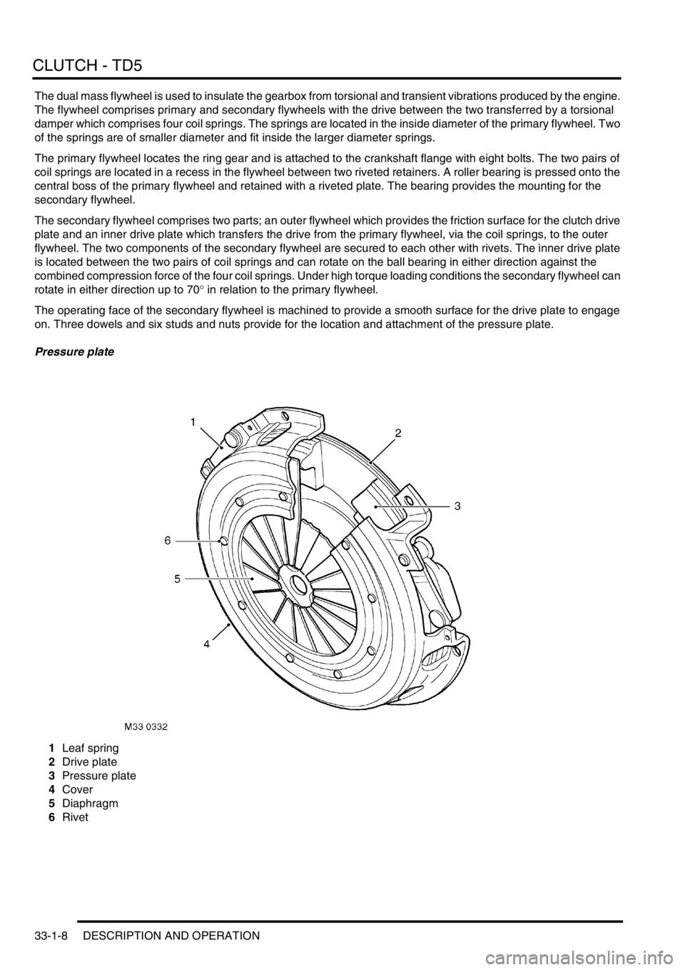
Pressure plate
1Leaf spring
2Drive plate
3Pressure plate
4Cover
5Diaphragm
6Rivet
Page 673 of 1672

CLUTCH - V8
33-2-6 DESCRIPTION AND OPERATION
Description
General
The clutch system is a conventional diaphragm type clutch operated by a hydraulic cylinder. The clutch requires no
adjustment to compensate for wear.
Hydraulic clutch
The hydraulic clutch comprises a master cylinder, slave cylinder and a hydraulic reservoir, which is also shared with
the braking system. The master and slave cylinders are connected to each other hydraulically by plastic and metal
pipes. The plastic section of the pipe allows ease of pipe routing and also absorbs engine movements and vibrations.
The master cylinder comprises a body with a central bore. Two ports in the body connect the bore to the hydraulic
feed pipe to the slave cylinder and the brake/clutch fluid reservoir. A piston is fitted in the bore and has an external
rod which is attached to the clutch pedal with a pin. Two coiled springs on the clutch pedal reduce the effort required
to depress the pedal.
The master cylinder is mounted on the bulkhead in the engine compartment and secured with two bolts. The cylinder
is connected to the shared brake/clutch reservoir on the brake servo by a braided connecting hose.
The slave cylinder is located on the left hand side of the gearbox housing and secured with two bolts. A heat shield
protects the underside of the cylinder from heat generated from the exhaust system. The slave cylinder comprises a
cylinder with a piston and a rod. A port in the cylinder body provides the attachment for the hydraulic feed pipe from
the master cylinder. A second port is fitted with a bleed nipple for removing air from the hydraulic system after
servicing. The piston rod locates on a clutch release lever located in the gearbox housing. The rod is positively
retained on the release lever with a clip.
Clutch mechanism
The clutch mechanism comprises a flywheel, drive plate, pressure plate, release lever and a release bearing. The
clutch mechanism is fully enclosed at the rear of the engine by the gearbox housing.
A clutch release bearing sleeve is attached in the gearbox housing with two bolts and located on two dowels. A spigot
with a ball end is formed on the release bearing sleeve and provides a mounting and pivot point for the clutch release
lever. A dished pivot washer is located on the ball of the spigot. When the release lever is located on the ball, the pivot
washer seats against the rear face of the release lever. A spring clip is located on the lever and the pivot washer and
secures the lever on the spigot. A small bolt retains the spring clip in position.
The release lever is forked at its inner end and locates on the clutch release bearing carrier. The outer end of the
release lever has a nylon seat which locates the slave cylinder piston rod. A second nylon seat, positioned centrally
on the release lever, locates on the ball spigot of the release bearing sleeve and allows the release lever to pivot freely
around the ball.
The clutch release bearing locates on the clutch release lever and the release bearing sleeve. The bearing is retained
on a carrier which has two flats to prevent the carrier rotating on the release lever. A clip retains the release lever on
the carrier. The bearing and carrier are not serviceable individually.
Page 674 of 1672

CLUTCH - V8
DESCRIPTION AND OPERATION 33-2-7
Flywheel
The flywheel is bolted to a flange on the rear of the crankshaft with six bolts. A dowel on the crankshaft flange ensures
that the flywheel is correctly located. A ring gear is fitted on the outside diameter of the flywheel and seats against a
flange. The ring gear is an interference fit on the flywheel and is installed by heating the ring and cooling the flywheel.
The ring gear is a serviceable item and can be replaced if damaged or worn.
The operating face of the flywheel is machined to provide a smooth surface for the drive plate to engage on. Three
dowels and six threaded holes provide for the location and attachment of the pressure plate. The flywheel is balanced
to ensure that it does not produce vibration when rotating. A machined slot, with a series of holes within the slot, is
located on the engine side of the flywheel. The slot accommodates the tip of the crankshaft position sensor which is
used by the Engine Control Module (ECM) for engine management.
+ ENGINE MANAGEMENT SYSTEM - V8, DESCRIPTION AND OPERATION, Description - engine
management.
Pressure plate
1Leaf spring
2Fulcrum ring
3Fulcrum ring
4Drive plate
5Pressure plate6Diaphragm
7Cover
8Rivet
9Retractor clip
The pressure plate assembly comprises a pressure plate, cover and diaphragm and is mounted on and rotates with
the flywheel.
Page 675 of 1672

CLUTCH - V8
33-2-8 DESCRIPTION AND OPERATION
The pressure plate is forged from cast iron and machined to provide a smooth surface for the drive plate to engage
on. Three lugs on the outer diameter of the pressure plate connect it via three leaf springs to the cover. The leaf
springs have two tempered steel leaves which assist in pulling the pressure plate away from the drive plate when the
clutch pedal is depressed.
The cover is made from pressed steel and houses and locates all pressure plate components. Shouldered rivets
support the diaphragm and fulcrum rings inside the cover. The cover also provides attachment for balance weights
when the pressure plate assembly is balanced. Three holes in the cover locate on the dowels on the flywheel and six
further holes provide for the attachment of the cover to the flywheel with six bolts and spring washers. Larger holes
in the cover provide ventilation for the drive plate and pressure plate and flywheel contact surfaces.
The diaphragm comprises a cast ring with eighteen fingers. The diaphragm is attached to the cover with nine
shouldered rivets. Two circular steel fulcrum rings are also secured by the shouldered rivets on each side of the
diaphragm. The fulcrum rings allow the diaphragm to pivot between them when the clutch is depressed or released.
When pressure is applied to the diaphragm fingers by the release bearing, the diaphragm pivots between the fulcrum
rings and moves away from the pressure plate. Retractor clips are secured to the pressure plate and are located on
the outer diameter of the diaphragm. The retractor clips ensure that the diaphragm remains in contact with the
pressure plate.
Drive plate
1Friction material
2Hub
3Damper spring
4Retainer plate
5Disc adaptor
6Stop pin
Page 680 of 1672

CLUTCH - V8
REPAIRS 33-2-13
REPAIRS
Clutch assembly
$% 33.10.01
Remove
1.Remove gearbox assembly.
+ MANUAL GEARBOX - R380,
REPAIRS, Gearbox - V8.
2.Restrain flywheel.
3.Working in diagonal sequence, progressively
loosen 6 bolts securing clutch cover to flywheel.
Remove bolts.
4.Remove clutch cover.
5.Remove clutch plate.
6.Renew all worn or damaged components.Refit
1.Clean clutch cover and flywheel mating faces
and spigot bush in end of crankshaft.
2.Fit LRT-12-001 to spigot bearing in crankshaft.
3.Fit clutch plate onto LRT-12-001, ensure side
marked 'flywheel side' is against flywheel.
4.Fit clutch cover and locate on dowels.
5.Fit clutch cover bolts and progressively tighten,
in diagonal sequence shown, to 40 Nm. (30
lbf.ft).
6.Fit gearbox assembly.
+ MANUAL GEARBOX - R380,
REPAIRS, Gearbox - V8.
Page 864 of 1672

REAR AXLE
REPAIRS 51-5
REPAIRS
Differential - assembly
$% 51.15.01
Remove
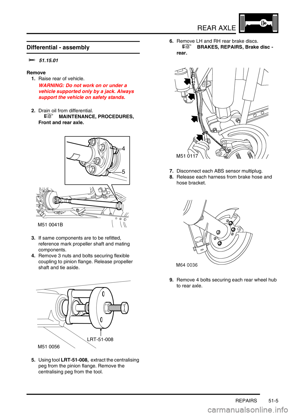
1.Raise rear of vehicle.
WARNING: Do not work on or under a
vehicle supported only by a jack. Always
support the vehicle on safety stands.
2.Drain oil from differential.
+ MAINTENANCE, PROCEDURES,
Front and rear axle.
3.If same components are to be refitted,
reference mark propeller shaft and mating
components.
4.Remove 3 nuts and bolts securing flexible
coupling to pinion flange. Release propeller
shaft and tie aside.
5.Using tool LRT-51-008, extract the centralising
peg from the pinion flange. Remove the
centralising peg from the tool.6.Remove LH and RH rear brake discs.
+ BRAKES, REPAIRS, Brake disc -
rear.
7.Disconnect each ABS sensor multiplug.
8.Release each harness from brake hose and
hose bracket.
9.Remove 4 bolts securing each rear wheel hub
to rear axle.
M51 0041B
5
4
M51 0056
LRT-51-008
Page 865 of 1672

REAR AXLE
51-6 REPAIRS
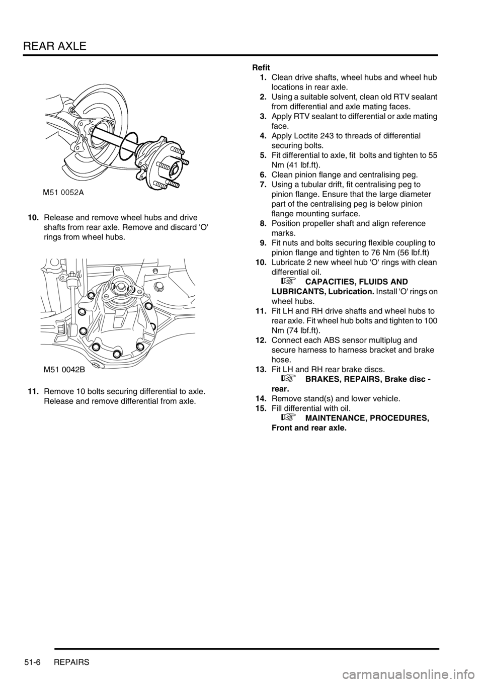
10.Release and remove wheel hubs and drive
shafts from rear axle. Remove and discard 'O'
rings from wheel hubs.
11.Remove 10 bolts securing differential to axle.
Release and remove differential from axle. Refit
1.Clean drive shafts, wheel hubs and wheel hub
locations in rear axle.
2.Using a suitable solvent, clean old RTV sealant
from differential and axle mating faces.
3.Apply RTV sealant to differential or axle mating
face.
4.Apply Loctite 243 to threads of differential
securing bolts.
5.Fit differential to axle, fit bolts and tighten to 55
Nm (41 lbf.ft).
6.Clean pinion flange and centralising peg.
7.Using a tubular drift, fit centralising peg to
pinion flange. Ensure that the large diameter
part of the centralising peg is below pinion
flange mounting surface.
8.Position propeller shaft and align reference
marks.
9.Fit nuts and bolts securing flexible coupling to
pinion flange and tighten to 76 Nm (56 lbf.ft)
10.Lubricate 2 new wheel hub 'O' rings with clean
differential oil.
+ CAPACITIES, FLUIDS AND
LUBRICANTS, Lubrication. Install 'O' rings on
wheel hubs.
11.Fit LH and RH drive shafts and wheel hubs to
rear axle. Fit wheel hub bolts and tighten to 100
Nm (74 lbf.ft).
12.Connect each ABS sensor multiplug and
secure harness to harness bracket and brake
hose.
13.Fit LH and RH rear brake discs.
+ BRAKES, REPAIRS, Brake disc -
rear.
14.Remove stand(s) and lower vehicle.
15.Fill differential with oil.
+ MAINTENANCE, PROCEDURES,
Front and rear axle.
M51 0042B