brake pads LAND ROVER DISCOVERY 2002 Workshop Manual
[x] Cancel search | Manufacturer: LAND ROVER, Model Year: 2002, Model line: DISCOVERY, Model: LAND ROVER DISCOVERY 2002Pages: 1672, PDF Size: 46.1 MB
Page 6 of 1672

CONTENTS
CONTENTS 3
Alarm handset battery ..................................................................................................................... 10-6
Road wheels ................................................................................................................................... 10-7
Tyres .............................................................................................................................................. 10-7
Brake pads, discs and calipers ....................................................................................................... 10-7
Road wheel speed sensors ............................................................................................................. 10-7
Brake fluid ....................................................................................................................................... 10-8
Fuel filter - diesel engine ................................................................................................................. 10-8
Fuel filter sedimenter ...................................................................................................................... 10-8
Road wheels ................................................................................................................................... 10-8
Radiator/Intercooler ........................................................................................................................ 10-8
Ambient air Temperature and pressure sensor .............................................................................. 10-8
Doors, bonnet and fuel filler flap ..................................................................................................... 10-9
Air suspension intake filter .............................................................................................................. 10-9
Anti-freeze....................................................................................................................................... 10-9
Cooling system ............................................................................................................................... 10-9
Spark plugs - V8 engine.................................................................................................................. 10-10
Air cleaner - V8 engine ................................................................................................................... 10-11
Air cleaner and dump valve - diesel engine .................................................................................... 10-11
Auxiliary drive belt ........................................................................................................................... 10-11
Auxiliary drive belt - V8 engine ....................................................................................................... 10-12
Auxiliary drive belt - diesel engine .................................................................................................. 10-12
Fluid reservoirs ............................................................................................................................... 10-12
Steering box .................................................................................................................................... 10-13
Battery ............................................................................................................................................. 10-13
Intercooler - diesel engine............................................................................................................... 10-14
Engine oil - V8 engine ..................................................................................................................... 10-14
Engine oil - diesel engine ................................................................................................................ 10-14
Centrifuge rotor – diesel engine ...................................................................................................... 10-15
Engine oil filter - diesel engine ........................................................................................................ 10-15
Engine oil filter – V8 engine ............................................................................................................ 10-15
Manual gearbox .............................................................................................................................. 10-16
Automatic gearbox ......................................................................................................................... 10-17
Transfer box .................................................................................................................................... 10-18
Front and rear axle .......................................................................................................................... 10-19
Propeller shafts ............................................................................................................................... 10-19
Anti-roll bar links ............................................................................................................................. 10-20
ACE actuators ................................................................................................................................. 10-21
ACE filter ......................................................................................................................................... 10-21
Brake hose, brake, fuel, ACE, clutch pipes and unions/electrical harnesses ................................ 10-22
Engine, gearbox, transfer box and axles ........................................................................................ 10-23
Exhaust system............................................................................................................................... 10-23
Steering box and front suspension ................................................................................................. 10-23
Steering rod ball joints ................................................................................................................... 10-25
Dampers and SLS height sensors .................................................................................................. 10-25
Front and rear axle suspension links .............................................................................................. 10-26
Towing bracket................................................................................................................................ 10-27
Engine mountings - V8 engine ........................................................................................................ 10-27
Road/roller test................................................................................................................................ 10-28
ENGINE - Td5 ........................................................................................... 12-1-1
DESCRIPTION AND OPERATION
Td5 Engine...................................................................................................................................... 12-1-1
Cylinder block components ............................................................................................................. 12-1-2
Page 19 of 1672

CONTENTS
16 CONTENTS
Brake system control component layout ......................................................................................... 70-1
Brake system control diagram ........................................................................................................ 70-2
Brake system hydraulic component layout ..................................................................................... 70-4
Description ...................................................................................................................................... 70-5
Operation ........................................................................................................................................ 70-20
DESCRIPTION AND OPERATION
Handbrake component layout ......................................................................................................... 70-25
Description ...................................................................................................................................... 70-26
ADJUSTMENTS
Handbrake .................................................................................................................................... 70-29
Brake system bleeding .................................................................................................................. 70-30
REPAIRS
Brake disc - front .......................................................................................................................... 70-33
Brake disc - rear ........................................................................................................................... 70-34
Master cylinder - brake ................................................................................................................. 70-35
Cable - handbrake ........................................................................................................................ 70-36
Switch - brake light ....................................................................................................................... 70-37
Brake pads - front ......................................................................................................................... 70-37
Brake pads - rear .......................................................................................................................... 70-38
Brake shoes - handbrake................................................................................................................ 70-39
Servo - brake .................................................................................................................................. 70-41
Vacuum pump - servo..................................................................................................................... 70-42
Housing - caliper - front ................................................................................................................ 70-43
Housing - caliper - rear ................................................................................................................. 70-44
ECU - Self levelling and anti locking brakes (SLABS) ................................................................. 70-45
Sensor – ABS – front ..................................................................................................................... 70-46
Sensor – ABS – rear ....................................................................................................................... 70-47
Modulator unit - ABS ...................................................................................................................... 70-47
Switch - Hill descent control............................................................................................................ 70-48
Switch - handbrake ....................................................................................................................... 70-49
RESTRAINT SYSTEMS ............................................................................ 75-1
DESCRIPTION AND OPERATION
SRS component layout ................................................................................................................... 75-1
SRS block diagram ......................................................................................................................... 75-2
Description - SRS ........................................................................................................................... 75-3
Operation - SRS ............................................................................................................................. 75-9
DESCRIPTION AND OPERATION
Description - seat belts ................................................................................................................... 75-11
REPAIRS
Seat belt - front .............................................................................................................................. 75-13
Seat belt - rear - centre ................................................................................................................. 75-13
Seat belt - rear - side .................................................................................................................... 75-15
Mounting - seat belt - 'B' post ...................................................................................................... 75-16
Seat belts - third row ....................................................................................................................... 75-17
Pre-tensioner - front seat belt ....................................................................................................... 75-18
Airbag module - drivers .................................................................................................................. 75-18
Airbag module - passenger ........................................................................................................... 75-19
DCU ................................................................................................................................................ 75-20
Rotary coupler ................................................................................................................................ 75-21
Airbag deployment tool - self test ................................................................................................... 75-22
Airbag module - drivers - deployment ............................................................................................. 75-23
Page 37 of 1672

GENERAL INFORMATION
03-2
Safety Instructions
Whenever possible, use a lift or pit when working
beneath vehicle, in preference to jacking. Chock
wheels as well as applying parking brake.
Jacking
Always use the recommended jacking points.
Always ensure that any lifting apparatus has
sufficient load capacity for the weight to be lifted.
Ensure the vehicle is standing on level ground prior
to lifting or jacking.
Apply the handbrake and chock the wheels.
WARNING: Do not work on or under a vehicle
supported only by a jack. Always support the
vehicle on safety stands.
Do not leave tools, lifting equipment, spilt oil, etc.
around or on the work bench area. Always keep a
clean and tidy work area.
Brake shoes and pads
Always fit the correct grade and specification of
brake linings. When renewing brake pads and brake
shoes, always replace as complete axle sets.Brake hydraulics
Observe the following recommendations when
working on the brake system:
lAlways use two spanners when loosening or
tightening brake pipe or hose connections.
lEnsure that hoses run in a natural curve and are
not kinked or twisted.
lFit brake pipes securely in their retaining clips
and ensure that the pipe cannot contact a
potential chafing point.
lContainers used for brake fluid must be kept
absolutely clean.
lDo not store brake fluid in an unsealed
container, it will absorb water and in this
condition would be dangerous to use due to a
lowering of its boiling point.
lDo not allow brake fluid to be contaminated with
mineral oil, or put new brake fluid in a container
which has previously contained mineral oil.
lDo not re-use brake fluid removed from the
system.
lAlways use clean brake fluid or a recommended
alternative to clean hydraulic components.
lAfter disconnection of brake pipes and hoses,
immediately fit suitable blanking caps or plugs to
prevent the ingress of dirt.
lOnly use the correct brake fittings with
compatible threads.
lObserve absolute cleanliness when working
with hydraulic components.
Cooling system caps and plugs
Extreme care is necessary when removing
expansion tank caps and coolant drain or bleed
screws when the engine is hot, especially if it is
overheated. To avoid the possibility of scalding,
allow the engine to cool before attempting removal.
Page 116 of 1672

MAINTENANCE
PROCEDURES 10-7
Road wheels
Remove
1.Mark the wheel to stud relationship to ensure
that the wheels are refitted in the same
position.
2.Loosen wheel nuts. Raise the vehicle to a
wheel-free condition and remove the wheel
nuts.
Tyres
Check
1.Check tyres for compliance with manufacturer's
specification; visually for cuts, lumps, bulges,
uneven tread wear and depth.
2.Check tyre pressures, condition and tread
depth. Measure the tread depth across the
width of the tyre and around the circumference.
Brake pads, discs and calipers
Check
1. Check front and rear brake pads for wear,
ensure all pads are wearing evenly.
2.Check brake discs for signs of cracking,
excessive scoring or oil contamination.
3.Check calipers for signs of fluid leaks.
4.Clean excessive deposits of brake dust from
pads, calipers and disc shields using brake
cleaner.
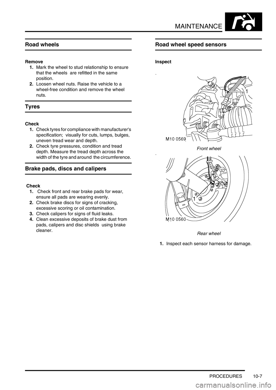
Road wheel speed sensors
Inspect
Front wheel
Rear wheel
1.Inspect each sensor harness for damage.
Page 1082 of 1672

BRAKES
REPAIRS 70-37
Switch - brake light
$% 70.35.42
The brake switch is set automatically during fitment.
If the setting is disturbed, the switch can be reset by
depressing the brake pedal and pulling the plunger
out of the switch body, until it contacts the pedal.
Remove
1.Remove 3 fasteners and move drivers side
lower closing panel aside.
2.Disconnect multiplug from brake light switch.
3.Remove brake light switch from pedal bracket.
Refit
1.Engage switch fully into pedal bracket location
and connect multiplug.
2.Position lower closing panel and secure with
fasteners.
Brake pads - front
$% 70.40.02
WARNING: Brake pads must be renewed in axle
sets only, otherwise braking efficiency may be
impaired.
Remove
1.Raise front of vehicle.
WARNING: Do not work on or under a
vehicle supported only by a jack. Always
support the vehicle on safety stands.
2.Remove road wheel(s).
3.Remove lower guide pin bolt from caliper and
pivot caliper housing upwards.
4.Remove 2 brake pads from caliper carrier.
Shims are part of the brake pads.
Refit
1.Rotate disc by hand and scrape all scale and
rust from around edge of disc.
2.Scrape rust from pad locating surfaces on
caliper.
3.Clean dust from calipers using brake cleaning
fluid.
WARNING: Do not use compressed air to
clean brake components. Dust from friction
materials can be harmful if inhaled.
Page 1083 of 1672

BRAKES
70-38 REPAIRS
4.Using tool LRT-70-500, press caliper pistons
fully into bores. Ensure that displaced fluid
does not overflow from reservoir.
5.Fit brake pads with chamfer towards leading
edge of disc.
6.Lower caliper housing over pads.
7.Ensure flats on guide pins locate with lugs on
caliper housing. fit new pivot bolt and tighten to
30 Nm (22 lbf.ft).
8.Fit road wheel(s) and tighten nuts to 140 Nm
(103 lbf.ft).
9.Remove stand(s) and lower vehicle.
10.Depress brake several times to set pad to disc
clearance.
11.Check and top-up brake fluid.
Brake pads - rear
$% 70.40.10
WARNING: Brake pads must be renewed in axle
sets only, otherwise braking efficiency may be
impaired.
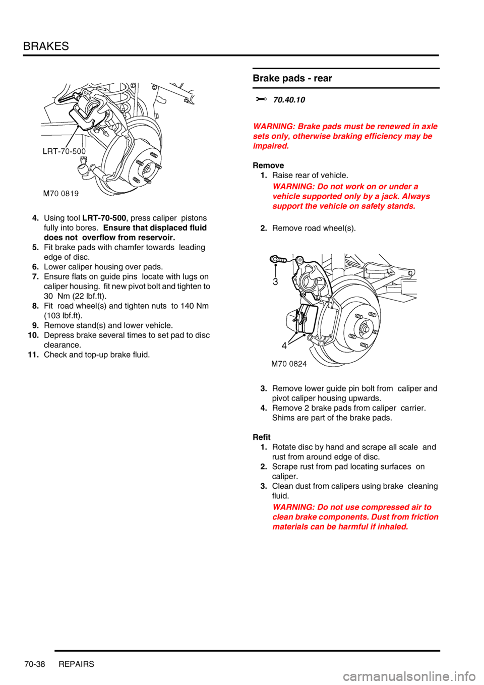
Remove
1.Raise rear of vehicle.
WARNING: Do not work on or under a
vehicle supported only by a jack. Always
support the vehicle on safety stands.
2.Remove road wheel(s).
3.Remove lower guide pin bolt from caliper and
pivot caliper housing upwards.
4.Remove 2 brake pads from caliper carrier.
Shims are part of the brake pads.
Refit
1.Rotate disc by hand and scrape all scale and
rust from around edge of disc.
2.Scrape rust from pad locating surfaces on
caliper.
3.Clean dust from calipers using brake cleaning
fluid.
WARNING: Do not use compressed air to
clean brake components. Dust from friction
materials can be harmful if inhaled.
Page 1084 of 1672

BRAKES
REPAIRS 70-39
4.Using tool LRT-70-500, press caliper pistons
fully into bores. Ensure that displaced fluid
does not overflow from reservoir.
5.Fit pads to caliper carrier.
6.Lower caliper housing over pads.
7.Ensure flats on guide pins locate with lugs on
caliper housing. fit new pivot bolt and tighten to
30 Nm (22 lbf.ft).
8.Fit road wheel(s) and tighten nuts to 140 Nm
(103 lbf.ft).
9.Remove stand(s) and lower vehicle.
10.Depress brake several times to set pad to disc
clearance.
11.Check and top-up brake fluid.
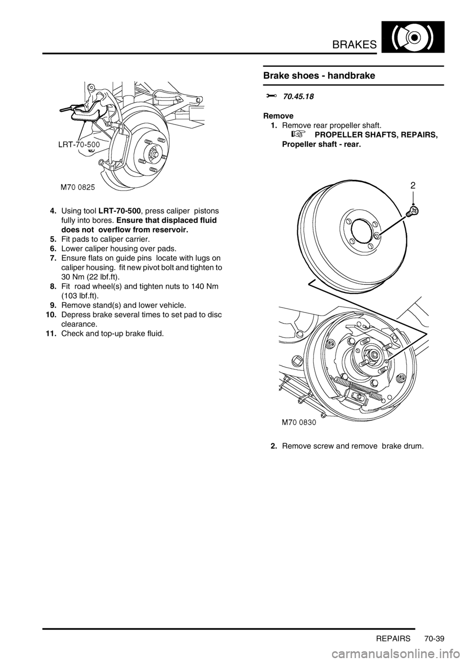
Brake shoes - handbrake
$% 70.45.18
Remove
1.Remove rear propeller shaft.
+ PROPELLER SHAFTS, REPAIRS,
Propeller shaft - rear.
2.Remove screw and remove brake drum.
Page 1088 of 1672

BRAKES
REPAIRS 70-43
Refit
1.Clean mating faces of alternator and vacuum
pump.
2.Fit vacuum pump to alternator and tighten
bolts to 8 Nm (6 lbf.ft).
3.Position alternator to engine and connect
multiplug.
4.Connect vacuum hose and oil drain hose to
vacuum pump and secure clips.
5.With assistance align alternator to mounting
bracket and fit but do not tighten bolt.
6.Fit bolt securing support stay to alternator and
tighten to 25 Nm (18 lbf.ft) .
7.Tighten bolt securing alternator to mounting
bracket to 45 Nm (33 lbf.ft).
8.Using new 'O' ring, connect oil supply pipe to
cylinder head and tighten to 10 Nm (7 lbf.ft).
9.Connect lead to alternator and tighten nut to 6
Nm (4.4 lbf.ft).
10.Fit auxiliary drive belt tensioner and tighten bolt
to 50 Nm (37 lbf.ft).
11.Fit auxiliary drive belt.
+ CHARGING AND STARTING,
REPAIRS, Belt - auxiliary drive.
Housing - caliper - front
$% 70.55.24
Remove
1.Raise front of vehicle, one side.
WARNING: Do not work on or under a
vehicle supported only by a jack. Always
support the vehicle on safety stands.
2.Remove road wheel(s).
3.Clamp brake hose to prevent fluid loss.
4.Remove brake hose banjo bolt and discard
sealing washers.
CAUTION: Always fit plugs to open
connections to prevent contamination.
5.Remove 2 guide pin bolts and remove caliper
housing from carrier.
6.Remove 2 brake pads from caliper carrier.
Page 1089 of 1672

BRAKES
70-44 REPAIRS
Refit
1.Rotate disc by hand and scrape all scale and
rust from around edge of disc. Clean location
surfaces on caliper bracket.
2.Clean dust from brake parts using brake
cleaning fluid.
WARNING: Do not use compressed air to
clean brake components. Dust from friction
materials can be harmful if inhaled.
3.Fit brake pads to caliper carrier.
4.Position caliper housing to carrier, align flats on
guide pins with caliper housing.
5.Fit guide pin bolts and tighten to 30 Nm (22
lbf.ft).
6.Clean banjo bolt and fit new sealing washers.
7.Position hose to caliper and tighten banjo bolt
to 32 Nm (24 lbf.ft).
8.Remove clamp from brake hose.
9.Bleed brake system.
+ BRAKES, ADJUSTMENTS, Brake
system bleeding.
10.Fit road wheel(s) and tighten nuts to 140 Nm
(103 lbf.ft).
11.Remove stand(s) and lower vehicle.
Housing - caliper - rear
$% 70.55.25
Remove
1.Raise rear of vehicle, one side.
WARNING: Do not work on or under a
vehicle supported only by a jack. Always
support the vehicle on safety stands.
2.Remove road wheel(s).
3.Clamp brake hose to prevent fluid loss.
4.Remove brake hose banjo bolt and discard
sealing washers.
CAUTION: Always fit plugs to open
connections to prevent contamination.
5.Remove 2 guide pin bolts and remove caliper
housing from carrier.
6.Remove 2 brake pads from caliper carrier.
Page 1090 of 1672

BRAKES
REPAIRS 70-45
Refit
1.Rotate disc by hand and scrape all scale and
rust from around edge of disc. Clean location
surfaces on caliper bracket.
2.Clean dust from brake parts using brake
cleaning fluid.
WARNING: Do not use compressed air to
clean brake components. Dust from friction
materials can be harmful if inhaled.
3.Fit brake pads to caliper carrier.
4.Position caliper housing to carrier, align flats on
guide pins with caliper housing.
5.Fit guide pin bolts and tighten to 30 Nm (22
lbf.ft).
6.Clean banjo bolt and fit new sealing washers.
7.Position hose to caliper and tighten banjo bolt
to 32 Nm (24 lbf.ft).
8.Remove clamp from brake hose.
9.Bleed brakes.
+ BRAKES, ADJUSTMENTS, Brake
system bleeding.
10.Fit road wheel(s) and tighten nuts to 140 Nm
(103 lbf.ft).
11.Remove stand(s) and lower vehicle.
ECU - Self levelling and anti locking
brakes (SLABS)
$% 70.65.01
Remove
1.Remove BCU.
+ BODY CONTROL UNIT, REPAIRS,
Body control unit (BCU).
2.Remove 5 multiplugs from SLABS ECU.
3.Remove multiplug from ACE ECU.
4.Remove lower nut and loosen upper nut
securing SLABS and ACE ECU bracket to
body.
5.Remove ECU's and bracket assembly.