run flat LAND ROVER DISCOVERY 2002 Workshop Manual
[x] Cancel search | Manufacturer: LAND ROVER, Model Year: 2002, Model line: DISCOVERY, Model: LAND ROVER DISCOVERY 2002Pages: 1672, PDF Size: 46.1 MB
Page 103 of 1672

LIFTING AND TOWING
08-2
Reverse procedure when removing vehicle from
stands.
Hydraulic ramps
Use only a 'drive on' type ramp which supports a
vehicle by it's own road wheels. If a 'wheel free'
condition is required, use a 'drive on' ramp
incorporating a 'wheel free' system that supports
under axle casings. Alternatively, place vehicle on a
firm, flat floor and support on axle stands.
TOWING
Towing
The vehicle has permanent four wheel drive. The
following towing instructions must be adhered
to:
Towing on 4 wheels with driver
Turn ignition key to position '1' to release steering
lock.
Select neutral in main gearbox and transfer gearbox.
Secure tow rope, chain or cable to towing eye.
Release the handbrake.
The brake servo and power assisted steering
system will not be functional without the engine
running. Greater pedal pressure will be required
to apply the brakes, the steering system will
require greater effort to turn the front road
wheels. The vehicle tow connection should be
used only in normal road conditions, 'snatch'
recovery should be avoided.Suspended tow
To prevent vehicle damage, front or rear
propeller shaft MUST BE removed, dependent
upon which axle is being trailed.
Mark propeller shaft drive flanges at transfer box and
axles with identification lines to enable the propeller
shaft to be refitted in its original position.
Remove the propeller shaft fixings, remove the shaft
from the vehicle.
If the front axle is to be trailed turn ignition key to
position '1' to release steering lock.
The steering wheel and/or linkage must be
secured in a straight ahead position. DO NOT use
the steering lock mechanism for this purpose.
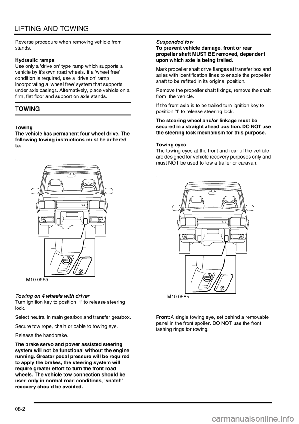
Towing eyes
The towing eyes at the front and rear of the vehicle
are designed for vehicle recovery purposes only and
must NOT be used to tow a trailer or caravan.
Front:A single towing eye, set behind a removable
panel in the front spoiler. DO NOT use the front
lashing rings for towing.
Page 137 of 1672

MAINTENANCE
10-28 PROCEDURES
4.Check condition of Engine - RH mounting
rubber
5.Check tightness of all mounting bolts.
+ TORQUE WRENCH SETTINGS,
Engine V8.
Road/roller test
WARNING: Roller test must be restricted to 3
mph (5 km/h). If 2 wheel rolling road is to be used,
disconnect propeller shaft from the transfer box
output shaft driving the axle which is NOT on the
rolling road.Testing
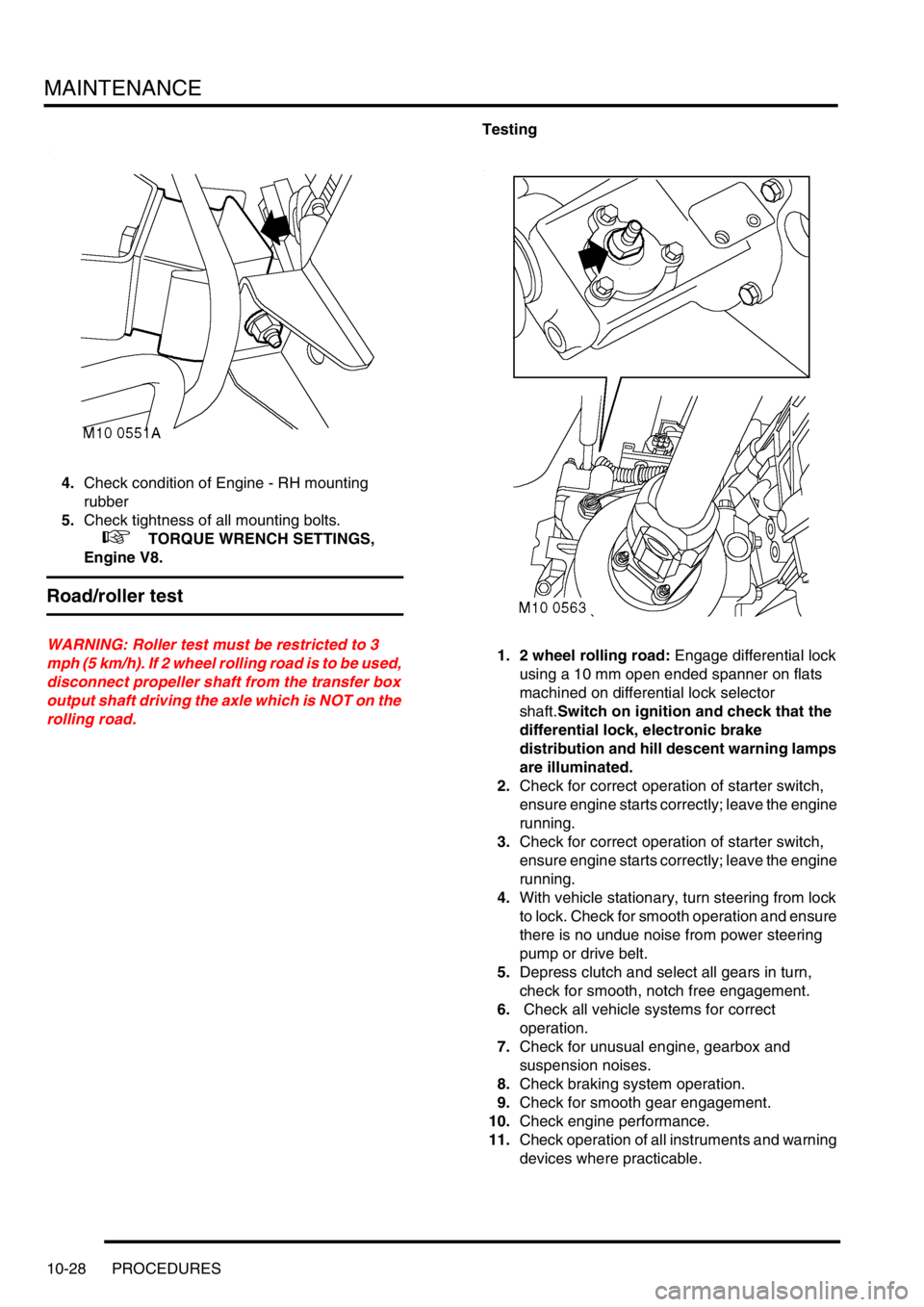
1. 2 wheel rolling road: Engage differential lock
using a 10 mm open ended spanner on flats
machined on differential lock selector
shaft.Switch on ignition and check that the
differential lock, electronic brake
distribution and hill descent warning lamps
are illuminated.
2.Check for correct operation of starter switch,
ensure engine starts correctly; leave the engine
running.
3.Check for correct operation of starter switch,
ensure engine starts correctly; leave the engine
running.
4.With vehicle stationary, turn steering from lock
to lock. Check for smooth operation and ensure
there is no undue noise from power steering
pump or drive belt.
5.Depress clutch and select all gears in turn,
check for smooth, notch free engagement.
6. Check all vehicle systems for correct
operation.
7.Check for unusual engine, gearbox and
suspension noises.
8.Check braking system operation.
9.Check for smooth gear engagement.
10.Check engine performance.
11.Check operation of all instruments and warning
devices where practicable.
Page 233 of 1672

ENGINE - TD5
12-1-94 OVERHAUL
15.Remove bolt and remove timing chain
adjustable guide.
16.Remove bolt and remove timing chain
lubrication jet.
17.Using tool LRT-12-092, remove and discard oil
seal from timing cover.
Inspection
1.Clean all components.
2.Check condition of timing chain running
surfaces on adjustable and fixed guides.
CAUTION: Adjustable guide fitted to Engine
Serial No. Prefixes 15P to 19P may be fitted
to early engines provided that timing chain
tensioner having a YELLOW coloured body
is also fitted.
3.Check timing chains and sprockets for signs of
wear.
CAUTION: Timing chains and sprockets
fitted to Engine Serial No. Prefixes 15P to
19P may be fitted to early engines as an
assembly only, oil pump drive sprockets are
interchangeable. Later timing chains have
BRONZE coloured timing links.
4.Check that drilling in timing chain lubrication jet
is clear.
5.Clean oil seal recess in timing cover and oil seal
running surface on crankshaft.
6.Remove all traces of sealant from mating faces
of timing cover and cylinder block using
suitable solvent.
CAUTION: Do not use metal scrapers.
7.Ensure bolt and dowel holes are clean and dry.
8.Clean oil pump sprocket bolt threads.Reassembly
1.Fit timing chain lubrication jet.
2.Fit timing chain lubrication jet Torx screw and
tighten to 10 Nm (7 lbf.ft).
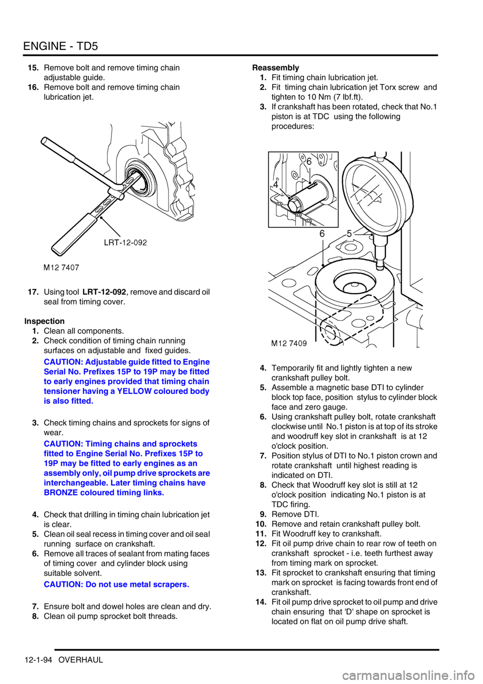
3.If crankshaft has been rotated, check that No.1
piston is at TDC using the following
procedures:
4.Temporarily fit and lightly tighten a new
crankshaft pulley bolt.
5.Assemble a magnetic base DTI to cylinder
block top face, position stylus to cylinder block
face and zero gauge.
6.Using crankshaft pulley bolt, rotate crankshaft
clockwise until No.1 piston is at top of its stroke
and woodruff key slot in crankshaft is at 12
o'clock position.
7.Position stylus of DTI to No.1 piston crown and
rotate crankshaft until highest reading is
indicated on DTI.
8.Check that Woodruff key slot is still at 12
o'clock position indicating No.1 piston is at
TDC firing.
9.Remove DTI.
10.Remove and retain crankshaft pulley bolt.
11.Fit Woodruff key to crankshaft.
12.Fit oil pump drive chain to rear row of teeth on
crankshaft sprocket - i.e. teeth furthest away
from timing mark on sprocket.
13.Fit sprocket to crankshaft ensuring that timing
mark on sprocket is facing towards front end of
crankshaft.
14.Fit oil pump drive sprocket to oil pump and drive
chain ensuring that 'D' shape on sprocket is
located on flat on oil pump drive shaft.
Page 1026 of 1672

REAR SUSPENSION
DESCRIPTION AND OPERATION 64-21
Normal ride height
When the vehicle is stationary, a door is open and the ignition is off, the SLS system will allow the rear of the vehicle
to lower to within 20 mm of the normal ride height as load is removed from the vehicle. The SLS system will only
operate the compressor to raise the rear of the vehicle when the engine is running, unless requested using the remote
handset.
Off-road mode (ORM)
ORM is used to raise the rear of the vehicle from normal ride height to the ORM ride height of 100 mm between the
tip of the bump stop and the axle.
ORM is activated by depressing the ORM switch located on the fascia for not less than 0.5 seconds. With the engine
running, all doors closed and the vehicle speed below 18 mph (30 km/h), the audible warning will sound once and the
ORM warning lamp in the instrument pack will start to flash when the switch is released. The compressor will be
started and the air control valves will be energised by the ECU to inflate the air springs and raise the rear of the vehicle.
When the full ORM height is reached, the ECU will terminate compressor operation and close the air valves. The ORM
warning lamp will stop flashing and remain continuously illuminated to inform the driver that the SLS system is in ORM.
When ORM is no longer required, depressing the ORM switch for not less than 0.5 seconds with all doors closed will
lower the SLS to normal ride height. The audible warning will sound once and the ORM warning lamp will flash as the
suspension lowers. The ECU energises the air control valves and the exhaust valve to release air pressure from the
air springs. When standard ride height is reached the ORM warning lamp will extinguish and the ECU will de-energise
the air control valves and the exhaust valve solenoids.
If the SLS is in ORM and the vehicle speed exceeds 18 mph (30 km/h), the ECU will lower the SLS to standard ride
height. The driver will be informed of this by an audible warning and the ORM warning lamp flashing as the suspension
lowers. When normal ride height is achieved, the ORM warning lamp will extinguish.
At sea level, the time to change the SLS from normal ride height to ORM or visa versa will take between 15 and 20
seconds.
If the ECU determines that conditions are not correct for SLS operation, i.e.; axle articulation or system fault, the
audible warning will sound three times to inform the driver that the ORM request has not been granted.
Extended mode
The extended mode is automatically operated by the ECU and requires no input from the driver. Extended mode
operates when the chassis is grounded causing the rear wheels to spin. This information is generated by the ABS
function of the SLABS ECU.
When the ECU senses that the chassis is grounded and the vehicle speed is less than 6 mph (10 km/h), the ECU will
operate the compressor and energise the air control valves for 25 seconds to raise the rear of the vehicle. This
operates irrespective of the mode that the SLS system is in at that time. To inform the driver, the ORM warning lamp
will flash continuously at all times that the system is in extended mode.
The driver can exit the extended mode by depressing the ORM switch for not less than 0.5 seconds or by exceeding
8 mph (13 km/h).
Remote handset SLS control
The remote handset is an accessory item which allows the SLS to be operated between normal ride height and bump
stop height to allow easier connection and disconnection of trailers. The remote handset is similar in appearance to
that of the remote door locking handset but does not have an integral key. A circular button with an arrow is used to
raise the SLS and an oval button with the 'Land Rover' logo is used to lower the SLS.
The remote handset control requires all doors to be closed and the ignition to be in position II, but the engine does
not need to be running.
Page 1191 of 1672

SEATS
76-5-6 DESCRIPTION AND OPERATION
Two pins within the seat switch pack control the seat fore/ aft motor. Both pins are normally earthed. Operating the
backward switch applies voltage to that pin while the other pin remains earthed. Operating the forward switch reverses
power and earth to the motor allowing the motor to run in the opposite direction.
Seat cushion front up/ down motor
The seat cushion front up/ down motor is a permanent magnet motor coupled to a rack and pinion assembly. Should
the motor seize or stick for 6 seconds or more an internal thermal cut out switch will trip to remove voltage from the
motor. Reset time for the switch is 35 seconds.
Two pins within the seat switch pack control the seat cushion front up/ down motor. Both pins are normally earthed.
Operating the up switch applies voltage to that pin while the other pin remains earthed. Operating the down switch
reverses power and earth to the motor allowing the motor to run in the opposite direction.
Seat cushion rear up/ down motor
The seat cushion rear up/ down motor is a permanent magnet motor coupled to a rack and pinion assembly. Should
the motor seize or stick for 6 seconds or more, an internal thermal cut out switch will trip to remove voltage from the
motor. Reset time for the switch is 35 seconds.
Two pins within the seat switch pack control the seat cushion rear up/ down motor. Both pins are normally earthed.
Operating the up switch applies voltage to that pin while the other pin remains earthed. Operating the down switch
reverses power and earth to the motor allowing the motor to run in the opposite direction.
Seat squab fore/ aft motor
The squab fore/ aft motor is a permanent magnet motor coupled to a rotary rack and pinion assembly. Should the
motor seize or stick for 6 seconds or more, an internal thermal cut out switch will trip to remove voltage from the motor.
Reset time for the switch is 35 seconds.
Two pins within the seat switch pack control the squab fore/ aft motor. Both pins are normally earthed. Operating the
fore switch applies voltage to that pin while the other pin remains earthed. Operating the aft switch reverses power
and earth to the motor allowing the motor to run in the opposite direction.
Lumbar pump
The lumbar pump inflates a bladder in the squab which provides extra support for the seat occupant. With no load on
the seat it takes approximately 10 seconds to completely inflate the bladder. With a load of 25 kg (55 lb) it takes
approximately 15 seconds to inflate the bladder. A pressure cut off switch in the system will operate at 0.12 to 1.93
bar (1.8 to 28 lbf.in
2). If a problem occurs with the lumbar bladder, e.g. a rupture, the whole lumbar system must be
replaced. The components are not serviceable.
Power comes from the seat switch pack through a 3A fuse in the satellite fuse box. The lumbar pump and the lumbar
deflate solenoid share an earth.
Lumbar deflate solenoid
The lumbar deflate solenoid vents the lumbar bladder to atmosphere to allow air to evacuate the bladder. The average
time to evacuate the bladder with a load of 25 kg (55 lb) is 9 seconds.
Power comes from the seat switch pack through a 3A fuse in the satellite fuse box. The lumbar deflate solenoid and
the lumbar pump share an earth.