spark plugs replace LAND ROVER DISCOVERY 2002 Workshop Manual
[x] Cancel search | Manufacturer: LAND ROVER, Model Year: 2002, Model line: DISCOVERY, Model: LAND ROVER DISCOVERY 2002Pages: 1672, PDF Size: 46.1 MB
Page 52 of 1672

GENERAL INFORMATION
03-17
Electrical Precautions
General
The following guidelines are intended to ensure the
safety of the operator while preventing damage to the
electrical and electronic components fitted to the
vehicle. Where necessary, specific precautions are
detailed in the individual procedures of this manual.
Equipment
Prior to commencing any test procedure on the
vehicle ensure that the relevant test equipment is
working correctly and any harness or connectors are
in good condition. It is particularly important to check
the condition of the lead and plugs of mains operated
equipment.
Polarity
Never reverse connect the vehicle battery and
always ensure the correct polarity when connecting
test equipment.
High voltage circuits
Whenever disconnecting live ht circuits always use
insulated pliers and never allow the open end of the
ht lead to contact other components, particularly
ECU's. Exercise caution when measuring the voltage
on the coil terminals while the engine is running, high
voltage spikes can occur on these terminals.
Connectors and harnesses
The engine compartment of a vehicle is a particularly
hostile environment for electrical components and
connectors:
lAlways ensure electrically related items are dry
and oil free before disconnecting and
connecting test equipment.
lEnsure disconnected multiplugs and sensors
are protected from being contaminated with oil,
coolant or other solutions. Contamination could
impair performance or result in catastrophic
failure.
lNever force connectors apart using tools to
prise apart or by pulling on the wiring harness.
lAlways ensure locking tabs are disengaged
before disconnection, and match orientation to
enable correct reconnection.
lEnsure that any protection (covers, insulation
etc.) is replaced if disturbed.Having confirmed a component to be faulty:
lSwitch off the ignition and disconnect the
battery.
lRemove the component and support the
disconnected harness.
lWhen replacing the component keep oily hands
away from electrical connection areas and push
connectors home until any locking tabs fully
engage.
Battery disconnection
Before disconnecting the battery, disable the alarm
system and switch off all electrical equipment. If the
radio is to be serviced, ensure the security code has
been deactivated.
CAUTION: To prevent damage to electrical
components, always disconnect the battery
when working on the vehicle's electrical system.
The ground lead must be disconnected first and
reconnected last.
CAUTION: Always ensure that battery leads are
routed correctly and are not close to any
potential chafing points.
Battery charging
Only recharge the battery with it removed from the
vehicle. Always ensure any battery charging area is
well ventilated and that every precaution is taken to
avoid naked flames and sparks.
Ignition system safety precautions
The vehicle's ignition system produces high voltage
and the following precautions should be observed
before carrying out any work on the system.
WARNING: Before commencing work on an
ignition system, ensure all high tension
terminals, adapters and diagnostic equipment
are adequately insulated and shielded to prevent
accidental personal contacts and minimise the
risk of shock. Wearers of surgically implanted
pacemaker devices should not be in close
proximity of ignition circuits or diagnostic
equipment.
Disciplines
Switch off the ignition prior to making any connection
or disconnection in the system to prevent electrical
surges caused by disconnecting 'live' connections
damaging electronic components.
Ensure hands and work surfaces are clean and free
of grease, swarf, etc. Grease collects dirt which can
cause electrical tracking (short-circuits) or high-
resistance contacts.
When handling printed circuit boards, treat with care
and hold by the edges only; note that some electronic
components are susceptible to body static.
Page 119 of 1672

MAINTENANCE
10-10 PROCEDURES
Spark plugs - V8 engine
Replace
Take great care when fitting spark plugs not
to cross-thread plug, otherwise costly
damage to cylinder head will result. It is
essential that correct grade of spark plugs
are fitted. Incorrect grade of spark plugs
may lead to piston overheating and engine
failure. Use only approved spark plugs, use
of unapproved spark plugs may cause the
misfire detection system to malfunction.
1.Disconnect battery earth lead.
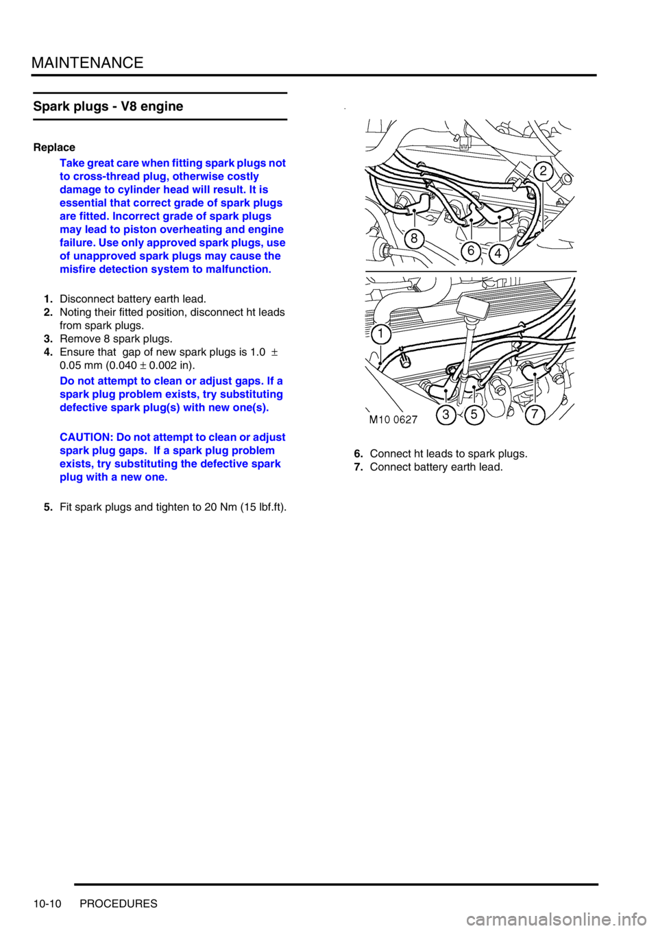
2.Noting their fitted position, disconnect ht leads
from spark plugs.
3.Remove 8 spark plugs.
4.Ensure that gap of new spark plugs is 1.0
±
0.05 mm (0.040
± 0.002 in).
Do not attempt to clean or adjust gaps. If a
spark plug problem exists, try substituting
defective spark plug(s) with new one(s).
CAUTION: Do not attempt to clean or adjust
spark plug gaps. If a spark plug problem
exists, try substituting the defective spark
plug with a new one.
5.Fit spark plugs and tighten to 20 Nm (15 lbf.ft).6.Connect ht leads to spark plugs.
7.Connect battery earth lead.
Page 464 of 1672

ENGINE MANAGEMENT SYSTEM - V8
DESCRIPTION AND OPERATION 18-2-7
The ECM controls the following outputs:
lFuel injectors (1 per cylinder).
lIgnition coils/ high tension leads/ spark plugs.
lFuel pump relay.
lIdle air control valve.
lHeated oxygen sensors.
lEVAP canister purge valve.
lEVAP canister vent solenoid (CVS) valve (where fitted).
lMalfunction Indicator Lamp (MIL)/ service engine soon lamp (where fitted).
lHill descent control (via SLABS interface).
lEVAP system fuel leak detection pump (where fitted)
lSecondary air injection pump (where fitted)
The ECM also interfaces with the following:
lDiagnostics via diagnostic connector with TestBook.
lController Area Network (CAN) link to EAT ECU.
lAir conditioning system.
lSelf Levelling & Anti-lock Braking System (SLABS) ECU.
lImmobilisation system via the body control unit (BCU).
lInstrument cluster.
lCruise control ECU
lActive Cornering Enhancement (ACE) ECU
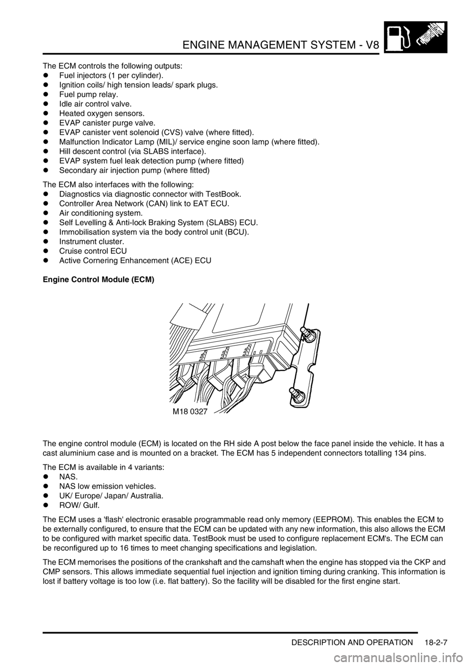
Engine Control Module (ECM)
The engine control module (ECM) is located on the RH side A post below the face panel inside the vehicle. It has a
cast aluminium case and is mounted on a bracket. The ECM has 5 independent connectors totalling 134 pins.
The ECM is available in 4 variants:
lNAS.
lNAS low emission vehicles.
lUK/ Europe/ Japan/ Australia.
lROW/ Gulf.
The ECM uses a 'flash' electronic erasable programmable read only memory (EEPROM). This enables the ECM to
be externally configured, to ensure that the ECM can be updated with any new information, this also allows the ECM
to be configured with market specific data. TestBook must be used to configure replacement ECM's. The ECM can
be reconfigured up to 16 times to meet changing specifications and legislation.
The ECM memorises the positions of the crankshaft and the camshaft when the engine has stopped via the CKP and
CMP sensors. This allows immediate sequential fuel injection and ignition timing during cranking. This information is
lost if battery voltage is too low (i.e. flat battery). So the facility will be disabled for the first engine start.