gas type LAND ROVER FREELANDER 2001 Workshop Manual
[x] Cancel search | Manufacturer: LAND ROVER, Model Year: 2001, Model line: FREELANDER, Model: LAND ROVER FREELANDER 2001Pages: 1007, PDF Size: 23.47 MB
Page 35 of 1007

GENERAL INFORMATION
03-4
Materials –
lkeep lids on containers of solvents;
lonly use the minimum quantity;
lconsider alternative materials;
lminimise over-spray when painting.
Gases –
luse the correct equipment for collecting
refrigerants;
ldon't burn rubbish on site.
Discharges to water
Most sites will have two systems for discharging
water: storm drains and foul drains. Storm drains
should only receive clean water, foul drains will take
dirty water.
The foul drain will accept many of the normal waste
waters such as washing water, detergents and
domestic type wastes, but oil, petrol, solvent, acids,
hydraulic oil, antifreeze and other such substances
should never be poured down the drain. If in any
doubt, speak to the local Water Company first.
Every precaution must be taken to prevent spillage of
oil, fuel, solvents etc. reaching the drains. All
handling of such materials must take place well away
from the drains and preferably in an area with a kerb
or wall around it, to prevent discharge into the drain.
If a spillage occurs, it should be soaked up
immediately. Having a spill kit available will make this
easier.
Additional precautions
Check whether the surface water drains are
connected to an oil/water separator, this could
reduce the pollution if an incident was to occur. Oil/
water separators require regular maintenance to
ensure effectiveness.
Checklist
Always adhere to the following:
Disposal –
lnever pour anything down a drain without first
checking that it is environmentally safe to do so,
and that it does not contravene any local
regulations or bye-laws;
lhave oil traps emptied regularly.
Spillage prevention –
lstore liquids in a walled area;
lmake sure the taps on liquid containers are
secure and cannot be accidentally turned on;
lprotect bulk storage tanks from vandalism by
locking the valves;
ltransfer liquids from one container to another in
an area away from open drains;
lensure lids are replaced securely on containers;
lhave spill kits available near to points of storage
and handling of liquids.Spill kits
Special materials are available to absorb a number of
different substances. They can be in granular form,
ready to use and bought in convenient containers for
storage. Disposal of used spill-absorbing material is
dealt with in the 'Waste Management' section.
Land contamination
Oils, fuels and solvents etc. can contaminate any soil
that they are allowed to contact. Such materials
should never be disposed of by pouring onto soil and
every precaution must be taken to prevent spillage
reaching soil. Waste materials stored on open
ground could also leak, or have polluting substances
washed off them that would contaminate the land.
Always store these materials in suitable skips or
other similarly robust containers.
Checklist
Always adhere to the following:
ldon't pour or spill anything onto the soil or bare
ground;
ldon't store waste materials on bare ground, see
'Spillage prevention' list.
Legal compliance
Some sites may have a discharge consent for
effluent discharge to the foul drain for a car wash etc.
It is important to know what materials are allowed in
the drain and to check the results of any monitoring
carried out by the Water Company.
Where paint spraying operations are carried out it
may be necessary to apply to the Local Authority for
an air emissions licence to operate the plant. If such
a licence is in operation, additional precautions will
be necessary to comply with the requirements, and
the results of any air quality monitoring must be
checked regularly.
Checklist
Always adhere to the following:
lknow what legal consents and licences apply to
the operations;
lcheck that the emissions and discharges
comply with legal requirements.
Page 41 of 1007
GENERAL INFORMATION
03-10
Joints and joint faces
General
Fit joints dry unless specified otherwise.
lAlways use the correct gaskets as specified.
lWhen joining compound is used, apply in a thin
uniform film to metal surfaces; take care to
prevent joining compound from entering
oilways, pipes or blind tapped holes.
lIf gaskets and/or joining compound is
recommended for use; remove all traces of old
joining material prior to reassembly. Do not use
a tool which will damage the joint faces and
smooth out any scratches or burrs using an oil
stone. Do not allow dirt or joining material to
enter any tapped holes or enclosed parts.
lPrior to reassembly, blow through any pipes,
channels or crevices with compressed air.
Locking devices
General
Always replace locking devices with one of the same
design.
Tab Washers
Always release locking tabs and fit new locking
washers, do not re-use locking tabs. Ensure the new
tab washer is the same design as that replaced.
Locking Nuts
Always use a backing spanner when loosening or
tightening locking nuts, brake and fuel pipe unions.
Roll Pins
Always fit new roll pins of an interference fit in the
hole.
Circlips
Always fit new circlips of the correct size for the
groove.
Locking wire
Always fit locking wire of the correct type. Arrange
wire so that its tension tends to tighten the bolt heads
or nuts to which it is fitted.
Keys and Keyways
Remove burrs from edges of keyways with a fine file
and clean thoroughly before attempting to refit key.
Clean and inspect key closely; keys are suitable for
refitting only if indistinguishable from new, as any
indentation may indicate the onset of wear.
Page 60 of 1007
GENERAL INFORMATION
03-29
Air conditioning system precautions
General
The air conditioning system contains fluids and
components which could be potentially hazardous to
the service engineer or the environment if not
serviced and handled correctly. The following
guidelines are intended to alert the service engineer
to potential sources of danger and emphasise the
importance of ensuring the integrity of the Air
Conditioning operating conditions and components
fitted to the vehicle.
Where necessary, additional specific precautions are
detailed in the relevant sections of this Manual which
should be referred to prior to commencing repair
operations.
The refrigerant used in the air conditioning system is
HFC-134a (Hydrofluorocarbon) R134a. Always
adhere to the following precautions:
WARNING: Servicing must only be carried out by
personnel familiar with both the vehicle system
and the charging and testing equipment. All
operations must be carried out in a well
ventilated area away from open flame and heat
sources.
WARNING: Do not allow a refrigerant container to
be heated by direct flame or to be placed near
any heating appliance. A refrigerant container
must not be heated above 50
°C.
Do not leave a container of refrigerant without its
cap fitted. Do not transport a container of
refrigerant that is unrestrained, especially in the
boot of a car.
WARNING: Do not smoke or weld in areas where
R134a is in use. Inhalation of concentrations of
vapour can cause dizziness, disorientation,
incoordination, narcosis, nausea or vomiting.
R134a is odourless and colourless. Do not
handle or discharge in an enclosed area, or any
area where the vapour and liquid can come in
contact with a naked flame or hot metal. R134a is
not flammable but can cause a highly toxic gas.
WARNING: Do not allow fluids other than R134a
or compressor lubricant to enter the air
conditioning system. Spontaneous combustion
may occur.WARNING: R134a is a hazardous liquid and when
handled incorrectly can cause serious injury.
Suitable protective clothing, consisting of face
protection, heat proof gloves, rubber boots and
rubber apron or waterproof overalls, must be
worn when carrying out operations on the air
conditioning system.
WARNING: Due to its low evaporating
temperature, R134a must be handled with care.
R134a splashed on any part of the body will
cause immediate freezing of that area. Also,
refrigerant cylinders and replenishment trolleys
when discharging will freeze skin to them if
contact is made.
WARNING: Under no circumstances should
refrigerant hoses be disconnected without first
discharging the system.
Do not disconnect any pipes in an air
conditioning refrigeration system unless trained
and instructed to do so. A refrigerant is used
which can cause blindness if allowed to contact
eyes.
WARNING: Refrigerant must always be recycled
before re-use to ensure that the purity of the
refrigerant is high enough for safe use in the air
conditioning system.
Recycling should always be carried out with
equipment which is design certified by
Underwriter Laboratory Inc. for compliance with
SAE J1991. Other equipment may not recycle
refrigerant to the required level of purity.
A R134a Refrigerant Recovery Recycling
Recharging Station must not be used with any
other type of refrigerant.
Refrigerant R134a from domestic and
commercial sources must not be used in motor
vehicle air conditioning systems.
Page 62 of 1007
GENERAL INFORMATION
03-31
When a major repair has been completed, a leak test
should be conducted; refer to the air conditioning
section of this manual for the correct procedure.
Refrigerant oil
Use an approved refrigerant lubricating oil:
ND Oil 8
CAUTION: Do not use any other type of
refrigerant oil.
CAUTION: Refrigerant oil easily absorbs water
and must not be stored for long periods. Do not
pour unused oil back into the container.
When renewing system components, add the
quantities of refrigerant oil recommended in the Air
Conditioning section of this manual.
Compressor
A new compressor is sealed and pressurised with
Nitrogen gas. When fitting a new compressor, slowly
release the sealing cap; gas pressure should be
heard to vent as the seal is broken.
CAUTION: A new compressor should always be
sealed and could be pressurised with nitrogen
gas. To avoid possible oil loss, release the
sealing cap(s) slowly. Do not remove the cap(s)
until immediately prior to connecting the air
conditioning pipes to the compressor.
Rapid refrigerant discharge
If the air conditioning system is involved in accident
damage and the system is punctured, the refrigerant
will discharge rapidly. The rapid discharge of
refrigerant will also result in the loss of most of the
oil from the system. The compressor must be
removed and all the remaining oil in the compressor
drained and refilled in accordance with the 'Air
Conditioning Compressor Replacement Procedure'.
Air conditioning compressor
replacement
A new compressor is supplied filled with a full charge
of (X cm3) of refrigerant oil.
A new compressor is supplied with an oil fill (X cm) of
120 cm
3.
A calculated quantity of oil must be drained from the
new compressor before fitting. To calculate the
quantity of oil to be drained:
1Remove the drain plug from the old
compressor.
2Invert the compressor and gravity drain the oil
into a calibrated measuring cylinder. Rotate the
compressor clutch to ensure the compressor is
completely drained.
3Note the quantity of oil drained (Y cm
3).
4Calculate the quantity of oil to be drained from
the new compressor using the following
formula:
X cm
3 – (Y cm3 + 20 cm3) = Q cm3
5Remove the drain plug from the new
compressor and drain Q cm3 of oil.
6Fit and tighten the compressor drain plug.
System components
When renewing system components, add the
following quantities of refrigerant oil:
lCondenser = 40 cm
3
lEvaporator = 30 cm 3
lReceiver drier = 15 cm 3
lPipe or hose = 5 cm 3
Page 67 of 1007

GENERAL DATA
04-4
Piston rings
Type: 2 compression, 1 oil control
⇒ Top compression ring Barrel edge, chrome plated
⇒ 2nd compression ring Taper faced
⇒ Oil control ring Bevelled ring with spring
New ring to groove clearance (axial play):
⇒ Top compression ring does not have to be measured
⇒ 2nd compression ring 0.05 - 0.09 mm (0.0020 - 0.0035 in.)
⇒ Oil control ring 0.03 - 0.07 mm (0.0012 - 0.0028 in.)
New ring fitted gap 30 mm (1.2 in) from top of bore:
⇒ Top compression ring 0.20 - 0.35 mm (0.008 - 0.014 in.)
⇒ 2nd compression ring 0.30 - 0.45 mm (0.012 - 0.018 in.)
⇒ Oil control ring 0.20 - 0.40 mm (0.008 - 0.016 in.)
Cylinder head
Type Aluminium alloy gravity die casting
Port configuration Cross flow
Intake ports 1 x helical, 1 x tangential
Cylinder head gasket:
⇒ Type Multi-layer steel
⇒ Selection:
⇒⇒ 1 hole Piston protrusion up to 0.91 mm (0.036 in)
⇒⇒ 2 hole Piston protrusion 0.92 - 1.03 mm (0.036 - 0.041 in)
⇒⇒ 3 hole Piston protrusion over 1.03 mm (0.041 in)
Camshaft
Type DOHC made from clear chill casting, hollow cast, negative cam radius;
vacuum pump driven from exhaust camshaft
Bearings 5 per camshaft
Drive Simplex chain
Radial runout 0.047 - 0.088 mm (0.0019 - 0.0035 in)
End float 0.15 - 0.33 mm (0.006 - 0.013 in.)
Bearing clearance 0.011 - 0.034 mm (0.0004 - 0.0013 in.)
Tappets
Type Hydraulic valve adjusters with roller finger levers
Page 75 of 1007

GENERAL DATA
04-12
Cylinder head
Type Aluminium alloy
Cylinder head gasket * Multi-layer steel
Cylinder head warp:
⇒ Lateral
⇒ Longitudinal0.025 mm (0.001 in)
0.2 mm (0.08 in)
Cylinder head height
Reface height - minimum118.95 - 119.05 mm (4.683 - 4.687 in)
118.95 mm (4.683 in)
Cylinder block
Type Cosworth cast aluminium alloy with bearing ladder bolted to bottom of
block
Cylinder liner type Damp, bottom half stepped - sliding fit into lower part of cylinder block
Cylinder liner bore:
⇒ RED grade A 80.000 - 80.015 mm (3.1496 - 3.1502 in.)
⇒ BLUE grade B 80.015 - 80.030 mm (3.1502 - 3.1508 in.)
Crankshaft
Material / Type Cast spheroidal graphite iron with cold rolled fillets on all journals
except outer mains
Crankshaft end-float
⇒ Service limit0.10 - 0.30 mm (0.004 - 0.012 in.)
0.40 mm (0.016 in.)
Main journal diameter:
⇒ Grade 1 67.743 - 67.749 mm (2.6670 - 2.6673 in.)
⇒⇒ Grade A (Green)
†
⇒⇒ Grade B (Yellow)†
⇒⇒ Grade C (Black)†
⇒ Grade 2 67.737 - 67.743 mm (2.6668 - 2.6670 in.)
⇒⇒ Grade A (Blue)
†
⇒⇒ Grade B (Green)†
⇒⇒ Grade C (Yellow)†
⇒ Grade 3 67.731 - 67.737 mm (2.6666 - 2.6668 in.)
⇒⇒ Grade A (Red)
†
⇒⇒ Grade B (Blue)†
⇒⇒ Grade C (Green)†
Maximum out of round 0.010 mm (0.0004 in.)
Main housing diameter:
⇒ Grade A 71.600 - 71.593 mm (2.8189 - 2.8186 in.)
⇒ Grade B 71.593 - 71.586 mm (2.8186 - 2.8183 in.)
⇒ Grade C 71.586 - 71.579 mm (2.8183 - 2.8181 in.)
Big-end journal diameter:
⇒ Grade A 54.049 - 54.055 mm (2.1279 - 2.1281 in.)
⇒ Grade B 54.043 - 54.049 mm (2.1277 - 2.1279 in.)
⇒ Grade C 54.037 - 54.043 mm (2.1274 - 2.1277 in.)
⇒ Maximum out of round 0.010 mm (0.0004 in.)
Big-end housing diameter:
⇒ Grade 7 57.677 - 57.671 mm (2.2707 - 2.2705 in.)
⇒⇒ Grade A (Green)
*
⇒⇒ Grade B (Blue)*
⇒⇒ Grade C (Red)*
⇒ Grade 8 57.671 - 57.665 mm (2.2705 - 2.2703 in.)
⇒⇒ Grade A (Yellow)
*
⇒⇒ Grade B (Green)*
General
Page 78 of 1007

GENERAL DATA
04-15
* New metal dowels supplied with gasket must be fitted
Valves
Stem diameter:
⇒ Inlet valves 5.952 - 5.967 mm (0.2343 - 0.2349 in.)
⇒ Exhaust valves 5.947 - 5.962 mm (0.2341 - 0.2347 in.)
Stem to guide clearance:
Inlet valves 0.033 - 0.063 mm (0.0013 - 0.0025 in.)
⇒ Service limit 0.07 mm (0.0028 in.)
Exhaust valves 0.038 - 0.078 mm (0.0015 - 0.0013 in.)
⇒ Service limit 0.11 mm (0.0043 in.)
Valve stem fitted height:
⇒ New 38.93 - 39.84 mm (1.533 - 1.569 in.)
⇒ Service limit 40.10 mm (1.579 in.)
Valve guide fitted height 6.0 mm (0.24 in.)
Valve guide inside diameter 6.000 - 6.025 mm (0.2362 - 0.2372 in.)
Head diameter:
⇒ Inlet valves 31.4 - 31.6 mm (1.236 - 1.244 in.)
⇒ Exhaust valves 27.3 - 27.5 mm (1.075 - 1.083 in.)
Valve seat width:
⇒ Inlet valves
⇒ Exhaust valves1.2 mm (0.05 in.)
1.6 mm (0.06 in)
Seat face angle:
⇒ Inlet valves
⇒ Exhaust valves45°
45°
Valve face angle:
⇒ Inlet valves
⇒ Exhaust valves45°
45°
Valve springs
Free length 47.6 mm (1.874 in.)
Fitted length 37.0 mm (1.457 in.)
Load at fitted length 210 ± 13 N
Load at top of lift 440 ± 22 N
Lubrication
Type Cast aluminium, wet sump with full flow filtration
Oil pump: Crankshaft driven, high pressure die cast body
⇒ Outer rotor end-float 0.04 - 0.09 mm (0.0016 - 0.0035 in.)
⇒ Inner rotor end-float 0.04 - 0.09 mm (0.0016 - 0.0035 in.)
⇒ Inner rotor tip 0.05 - 0.13 mm (0.002 - 0.005 in)
⇒ Outer rotor to body diameterical clearance
0.13 - 0.23 mm (0.0051 - 0.0091 in.)
⇒ Rotor body to drive gear clearance (pump not fitted)
0.15 - 0.25 mm (0.0059 - 0.0098 in.)
Relief valve spring free length 38.90 mm (1.531 in)
Oil filter Full-flow disposable cartridge
Oil cooler Partial flow type
Pressure at idle (min.) 1.0 bar (14.5 lbf.in
2)
Pressure at 3000 rev/min. 3.0 bar (43.5 lbf.in
2)
Relief valve opening pressure 4.1 bar (59.5 lbf.in
2)
Low oil pressure switch opening pressure 0.3 - 0.5 bar (4.4 - 7.3 lbf.in
2) General
Page 145 of 1007
CAPACITIES, FLUIDS, LUBRICANTS AND SEALANTS
09-2
Fluids
Fuel
Always use the following recommended fuels:
Petrol engines
Use unleaded petrol with a minimum octane rating of
95 RON to ENN 228 specification.
In an emergency (and only if the correct fuel is
unavailable), lower octane rated fuel can be used for
very limited periods of moderate, low speed
motoring, provided engine 'knocking' does not occur.
Fuels of 90 RON is used in certain markets; 90 RON
fuel can be used regularly ONLY if the engine has
been tuned specifically to suit low octane fuel.
Certain markets use fuel containing a 23% Ethanol
additive.
K1.8 and KV6 engines are also available for use with
a low octane leaded fuel specification in some
markets.
Diesel engines
Use a good quality diesel fuel or automotive gas oil
(AGO) conforming to EN 590 specification.
It is important that the sulphur content of diesel fuel
does not exceed 0.3%.
Ensure the fuel filter element is changed at the
recommended intervals.
+ MAINTENANCE, MAINTENANCE, Fuel
Filter - Diesel.
Brake Fluid
Use only DOT 4 brake fluid. DO NOT use brake fluid
of a different specification.
PAS fluid
Use Texaco 9226 fluid.Anti-freeze solutions
The overall anti-freeze concentration should not fall,
by volume, below 50% to ensure that the anti-
corrosion properties of the coolant are maintained.
Anti-freeze concentrations greater than 60% are not
recommended as cooling efficiency will be impaired.
Use Havoline Extended Life Coolant (XLC), or any
ethylene glycol based anti-freeze (containing no
methanol) with only Organic Acid Technology (OAT)
corrosion inhibitors, to protect the cooling system.
CAUTION: No other anti-freeze should be used
with Havoline Extended Life Coolant.
The cooling system should be drained, flushed and
refilled with the correct amount of anti-freeze
solution at the intervals given on the Service
Maintenance Check Sheet.
After filling with anti-freeze solution, attach a warning
label to a prominent position on the vehicle stating
the type of anti-freeze contained in the cooling
system to ensure that the correct type is used for
topping-up.
The following recommended quantities of anti-freeze
will provide frost protection to -36 °C (-33 °F):
Engine – Td4
Engine – K1.8
Engine – KV6
Concentration 50%
Amount of anti-freeze 3.75 litres
(6.625 imp. pts)
Concentration 50%
Amount of anti-freeze 2.9 litres
(5.125 imp. pts)
Concentration 50%
Amount of anti-freeze 3.9 litres
(6.875 imp. pts, )
Page 771 of 1007
PANEL REPAIRS
77-2-16 WELDING PROCEDURES
General Welding Precautions
General
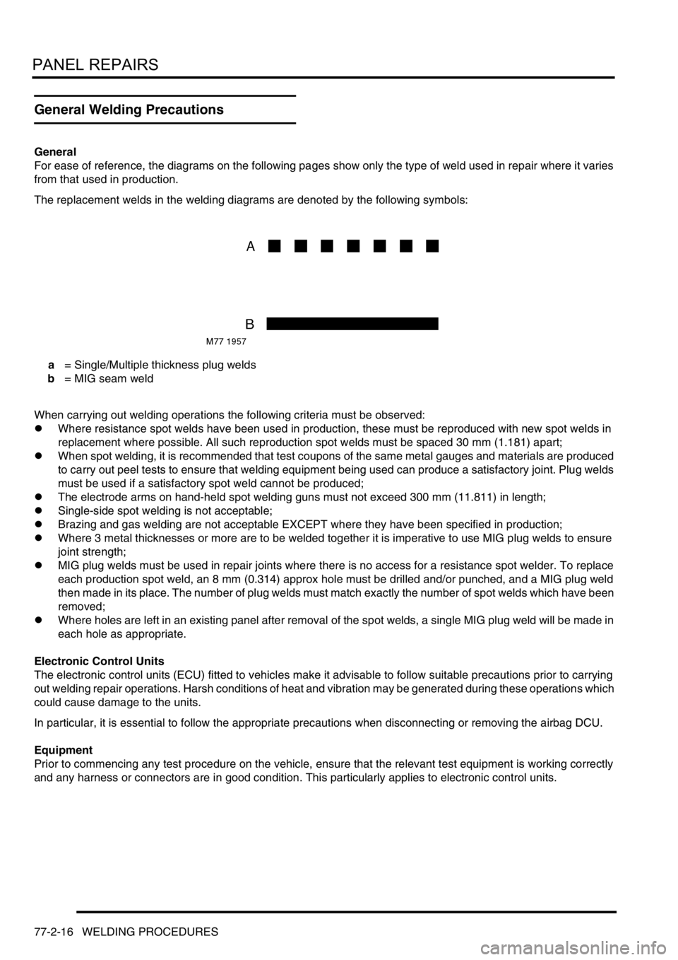
For ease of reference, the diagrams on the following pages show only the type of weld used in repair where it varies
from that used in production.
The replacement welds in the welding diagrams are denoted by the following symbols:
a = Single/Multiple thickness plug welds
b = MIG seam weld
When carrying out welding operations the following criteria must be observed:
lWhere resistance spot welds have been used in production, these must be reproduced with new spot welds in
replacement where possible. All such reproduction spot welds must be spaced 30 mm (1.181) apart;
lWhen spot welding, it is recommended that test coupons of the same metal gauges and materials are produced
to carry out peel tests to ensure that welding equipment being used can produce a satisfactory joint. Plug welds
must be used if a satisfactory spot weld cannot be produced;
lThe electrode arms on hand-held spot welding guns must not exceed 300 mm (11.811) in length;
lSingle-side spot welding is not acceptable;
lBrazing and gas welding are not acceptable EXCEPT where they have been specified in production;
lWhere 3 metal thicknesses or more are to be welded together it is imperative to use MIG plug welds to ensure
joint strength;
lMIG plug welds must be used in repair joints where there is no access for a resistance spot welder. To replace
each production spot weld, an 8 mm (0.314) approx hole must be drilled and/or punched, and a MIG plug weld
then made in its place. The number of plug welds must match exactly the number of spot welds which have been
removed;
lWhere holes are left in an existing panel after removal of the spot welds, a single MIG plug weld will be made in
each hole as appropriate.
Electronic Control Units
The electronic control units (ECU) fitted to vehicles make it advisable to follow suitable precautions prior to carrying
out welding repair operations. Harsh conditions of heat and vibration may be generated during these operations which
could cause damage to the units.
In particular, it is essential to follow the appropriate precautions when disconnecting or removing the airbag DCU.
Equipment
Prior to commencing any test procedure on the vehicle, ensure that the relevant test equipment is working correctly
and any harness or connectors are in good condition. This particularly applies to electronic control units.