parking brake LAND ROVER FREELANDER 2001 Workshop Manual
[x] Cancel search | Manufacturer: LAND ROVER, Model Year: 2001, Model line: FREELANDER, Model: LAND ROVER FREELANDER 2001Pages: 1007, PDF Size: 23.47 MB
Page 24 of 1007

CONTENTS
CONTENTS 21
WINDOWS ................................................................................................ 86-5-1
REPAIRS
Motor & control unit - front door - 3 door ......................................................................................... 86-5-1
Motor & control unit - front door - 5 door ......................................................................................... 86-5-2
Switch - master window - 5 door - from 04MY ................................................................................ 86-5-2
Relay - control - tail door glass ....................................................................................................... 86-5-3
Microswitch - hardtop sensing - 3 door ........................................................................................... 86-5-4
Relay - heated front screen ........................................................................................................... 86-5-5
Switch - backlight heater ................................................................................................................. 86-5-6
IN CAR ENTERTAINMENT ...................................................................... 86-6-1
REPAIRS
Radio - up to 04MY ......................................................................................................................... 86-6-1
Radio/CD - from 04MY .................................................................................................................... 86-6-2
Speaker - rear - 3 door .................................................................................................................... 86-6-3
Speaker - rear - 5 door .................................................................................................................... 86-6-3
Speaker - front ................................................................................................................................ 86-6-4
Aerial - manual - 3 door .................................................................................................................. 86-6-4
Aerial - manual - 5 door .................................................................................................................. 86-6-5
Coaxial lead - front aerial - 3 door ................................................................................................... 86-6-6
Coaxial lead - front aerial - 5 door ................................................................................................... 86-6-7
Speaker - tweeter - front ................................................................................................................. 86-6-8
Speaker - tweeter - rear - 3 door ..................................................................................................... 86-6-9
Amplifier - power ............................................................................................................................ 86-6-10
Sub-woofer assembly .................................................................................................................... 86-6-11
Coaxial lead - extension.................................................................................................................. 86-6-12
HARNESSES ............................................................................................ 86-7-1
REPAIRS
Fuse box - passenger compartment ............................................................................................... 86-7-1
Harness - main ................................................................................................................................ 86-7-2
Harness - tailgate ............................................................................................................................ 86-7-12
Harness - interior lights - 5 door ...................................................................................................... 86-7-15
Harness - front door - 5 door ........................................................................................................... 86-7-15
Harness - rear door ......................................................................................................................... 86-7-16
DRIVER CONTROLS ................................................................................ 86-8-1
REPAIRS
Switch - remote control - audio system .......................................................................................... 86-8-1
Switch - park distance control (PDC) - from 04 MY ........................................................................ 86-8-1
Control unit (ECU) - parking aid - from 04MY ................................................................................. 86-8-2
Sensor - parking aid - rear - from 04MY ......................................................................................... 86-8-2
Sounder - parking aid - rear - from 04MY ....................................................................................... 86-8-3
Switch - handbrake warning ............................................................................................................ 86-8-3
Switch - hazard warning - from 04MY ............................................................................................. 86-8-4
Cigar lighter - front .......................................................................................................................... 86-8-4
Switch - control - exterior mirror ...................................................................................................... 86-8-5
Page 29 of 1007

INTRODUCTION
01-4
HRW Heated Rear Window
ht/HT High tension
HSLA High Strength Low Alloy
IACV Idle Air Control Valve
IAT Intake Air Temperature
ICE In-Car Entertainment
i.dia. Internal diameter
IDM Intelligent Driver Module
IF Intermediate Frequency
in Inch
in
2Square inch
in3Cubic inch
ILT Inlet Throttle
ISO International Organisation for
Standardisation
ITS Inflatable Tubular Structure
k Thousand
kg Kilogramme
kg/h Kilogrammes per hour
km Kilometre
km/h Kilometres per hour
kPa KiloPascal
KS Knock Sensor
lb(s) Pounds
lbf Pounds force
lbf.in Pounds force inches
lbf/in
2Pounds per square inch
lbf.ft Pounds force feet
λLambda
lc Low compression
LCD Liquid Crystal Display
LED Light Emitting Diode
LEV Low Emission Vehicle
LH Left-Hand
LHD Left-Hand Drive
LSM Light Switch Module
LVS Liquid Vapour Separator
mMetre
µMicro
MAF Mass Air Flow
MAP Manifold Absolute Pressure
MFU Multi-Function Unit
MFL Multi-Function Logic
max. Maximum
MEMS Modular Engine Management
System
MIG Metal/Inert Gas
MIL Malfunction Indicator Lamp
MPa MegaPascal
MOSFET Metal Oxide Semiconductor Field
Effect Transistor
min. Minimum
- Minus (tolerance)
' Minute (angle)
mm Millimetre
mph Miles per hour MPi Multi-Point injection
MV Motorised Valve
MY Model Year
NAS North American Specification
(-) Negative (electrical)
Nm Newton metre
No. Number
NO
2Nitrogen Dioxide
NO
xOxides of Nitrogen
NTC Negative Temperature
Coefficient
NRV Non Return Valve
OBD On Board Diagnostics
OBM On Board Monitoring
o.dia. Outside diameter
OAT Organic Acid Technology
ORM Off-road Mode
ΩOhm
PAS Power Assisted Steering
PCB Printed Circuit Board
PCV Positive Crankcase Ventilation
PDC Parking Distance Control
PDOP Position Dilation Of Precision
PI Programme Information
PPS Pulse Per Second
PS Programme Service
psi Pounds per square inch
pts. Pints
% Percentage
+ Plus (tolerance) or Positive
(electrical)
±Plus or minus (tolerance)
PTC Positive Temperature Coefficient
PTFE Polytetrafluorethylene
PWM Pulse Width Modulation
RDS Radio Data Service
rRadius
:Ratio
ref Reference
REG Regionalisation
RES Rover Engineering Standards
rev/min Revolutions per minute
RF Radio Frequency
RGB Red / Green / Blue
RH Right-Hand
RHD Right-Hand Drive
ROM Read Only Memory
RON Research Octane Number
ROV Roll Over Valve
ROW Rest Of World
SAE Society of Automotive Engineers
SAI Secondary Air Injection
" Second (angle)
SLABS Self Levelling and Anti-Lock
Brake System
SLS Self Levelling Suspension
SOHC Single Overhead Camshaft
SPE Single Point Entry
Page 33 of 1007
GENERAL INFORMATION
03-2
Environmental Protection Precautions
It is illegal to pour used oil on to the ground, down
sewers or drains, or into water courses.
Burning of used engine oil in small space heaters or
boilers should only be considered for units of
approved design and in compliance with the
equipment manufacturer's recommendations. The
heating system must meet the regulatory standards
of HMIP for small burners of less than 0.4 MW. If in
doubt check with the appropriate local authority and/
or manufacturer of the approved appliance.
Dispose of used oil and filters through authorised
waste disposal contractors and licensed waste
disposal sites, or through the waste oil reclamation
trade. If in doubt, contact the Local Authority for
advice on disposal facilities.
Safety instructions
Whenever possible, use a lift or pit when working
beneath vehicle, in preference to jacking. Chock
wheels as well as applying parking brake.
Jacking
Always use the recommended jacking points. The
recommended jacking points are shown in
theLIFTING AND TOWING sub-section of the
INFORMATION section.
Always ensure that any lifting apparatus has
sufficient load capacity for the weight to be lifted.
Ensure the vehicle is standing on level ground prior
to lifting or jacking.
Apply the handbrake and chock the wheels.
WARNING: Do not work on or under a vehicle
supported only by a jack. Always support the
vehicle on safety stands.
Do not leave tools, lifting equipment, spilt oil, etc.,
around or on the work bench area. Always keep a
clean and tidy work area.
Brake shoes and pads
Always fit the correct grade and specification of
brake linings. When renewing brake pads and brake
shoes always replace as complete axle sets only.
Page 94 of 1007

GENERAL DATA
04-31
Brakes
Front disc brakes
Type Pin-slider caliper with ventilated disc, self-adjusting
Disc diameter 262 mm (10.31 in)
Disc thickness:
⇒ New
⇒ Service limit20.8 - 21.00 mm (0.818 - 0.826 in)
18.00 mm (0.708 in)
Disc run-out (maximum) 0.040 mm (0.0016 in), with wheel on
Pad minimum thickness 3.00 mm (0.118 in)
Rear drum brakes
Drum inside diameter 254 mm (10.00 in)
Drum wear limit 255.49 mm (10.059 in), discard drum
Lining minimum thickness 2.00 mm (0.079 in)
Drum ovality limit 0.012 mm (0.0005 in)
Master cylinder
Bore diameter 23.80 mm (0.937 in)
Brake servo
Servo boost ratio 4.5 : 1
Parking brake
Type Mechanically operated via twin cables on rear drum brakes
Anti-lock braking system
Circuit type Diagonal split, dual circuit, 4-sensor ABS
ABS type TEVES MK20 with ABS, Hill Descent Control (HDC), Electronic
Traction Control (ETC) and Electronic Brakeforce Distribution (EBD)
Page 140 of 1007
LIFTING AND TOWING
08-1
LIFTING AND TOWING
Jacking
The following instructions must be carried out before
raising the vehicle off the ground:
lUse a solid level surface.
lApply parking brake.
lSelect 1st. gear in main gearbox and ensure
HDC is not selected.
CAUTION: To avoid damage to under body
components of the vehicle, adhere to the
following jacking procedures:
DO NOT POSITION JACKS OR AXLE STANDS
UNDER THE FOLLOWING COMPONENTS:
lBumpers
lBrake or Fuel lines
lExhaust pipe
lSuspension components
lSteering rack and linkages
lFuel tank
lEngine sump
lGearbox
lIRD unit
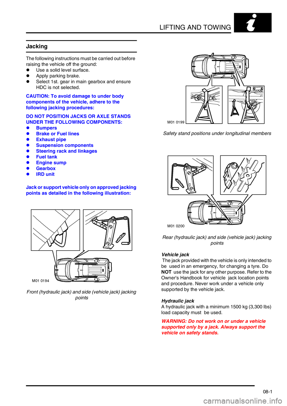
Jack or support vehicle only on approved jacking
points as detailed in the following illustration:
Front (hydraulic jack) and side (vehicle jack) jacking
pointsSafety stand positions under longitudinal members
Rear (hydraulic jack) and side (vehicle jack) jacking
points
Vehicle jack
The jack provided with the vehicle is only intended to
be used in an emergency, for changing a tyre. Do
NOT use the jack for any other purpose. Refer to the
Owner's Handbook for vehicle jack location points
and procedure. Never work under a vehicle only
supported by the vehicle jack.
Hydraulic jack
A hydraulic jack with a minimum 1500 kg (3,300 lbs)
load capacity must be used.
WARNING: Do not work on or under a vehicle
supported only by a jack. Always support the
vehicle on safety stands.
Page 141 of 1007
LIFTING AND TOWING
08-2
Raising the front of a vehicle
Position the cup of the hydraulic arm under the
centre of the front body crossmember assembly.
Use jack to raise front road wheels to enable safety
stands to be installed under the front end of each
longitudinal member.
Carefully lower jack until vehicle sits securely on
safety stands.
Before working on the underside of a vehicle re-
check the stability of the vehicle on the stands.
Use the reverse procedure when removing a vehicle
from stands.
NOTE: For some repair operations it may be
necessary to use a jack to support the engine under
the sump. In this case, a block of wood should be
used on the jack to protect the sump.
Raising the rear of a vehicle
Position cup of hydraulic arm under the centre of the
rear subframe crossmember at the position
identified by the embossed arrows.
Use jack to raise rear road wheels to enable safety
stands to be installed under the rear ends of the
body longitudinal members.
Carefully lower jack until vehicle sits securely on
safety stands.
Before working on the underside of a vehicle, re-
check the stability of the vehicle on the stands.
Use the reverse procedure when removing a vehicle
from stands.
Wheel-free lift
Locate the lifting pads under the ends of the body
longitudinal members. Raise the ramp to support the
weight of the vehicle, ensure the vehicle is secure on
the lifting pads, then raise the ramp to the required
height.
Towing
General
The vehicle has permanent four wheel drive. The
following instructions must be adhered to:
Towing the vehicle on all four wheels with driver
operating steering and brakes
lTurn ignition key to position '1' to release
steering lock and then to position 'II' to enable
the brake lights, wipers and direction indicators
to be operated, if necessary.
l Select neutral in gearbox and ensure HDC (hill
descent control) is deselected.
lSecure tow rope, chain or cable to towing eye.
lRelease the parking brake.
CAUTION: The brake servo and power assisted
steering system will not be functional without the
engine running. Greater pedal pressure will be
required to apply the brakes and the steering
system will require greater effort to turn the front
road wheels. The vehicle tow connection should
only be used under normal road conditions,
'snatch' recovery should be avoided.
Suspended tow by breakdown vehicle
Mark propeller shaft drive flanges and mating flanges
with identification lines to enable the propeller shaft
to be refitted in its original position.
Remove the propeller shaft fixings then remove the
shaft from the vehicle.
CAUTION: To prevent vehicle damage, rear
propeller shaft MUST BE removed.
Page 142 of 1007
LIFTING AND TOWING
08-3
If the front of the vehicle is to be trailed, turn ignition
key to position 'I' to release steering lock.
WARNING: Do not turn the starter switch to
position '0' or remove the ignition key while the
vehicle is being towed.
CAUTION: If it is considered unsafe to turn the
starter switch to position '1' due to accident
damage or an electrical fault; disconnect the
battery before turning the ignition switch.
CAUTION: The steering wheel and/or linkage
must be secured in a straight ahead position. DO
NOT use the steering lock mechanism for this
purpose.
CAUTION: Under no circumstances should the
vehicle be towed or recovered by means of
lashing to the rear subframe. Serious damage to
the subframe and body could result.
CAUTION: Only use the rear towing eye for
towing another vehicle.
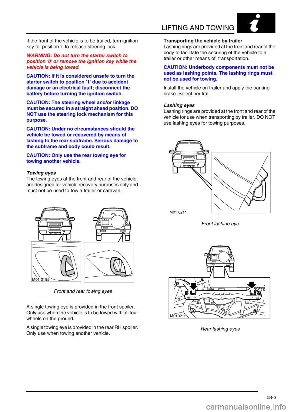
Towing eyes
The towing eyes at the front and rear of the vehicle
are designed for vehicle recovery purposes only and
must not be used to tow a trailer or caravan.
Front and rear towing eyes
A single towing eye is provided in the front spoiler.
Only use when the vehicle is to be towed with all four
wheels on the ground.
A single towing eye is provided in the rear RH spoiler.
Only use when towing another vehicle.Transporting the vehicle by trailer
Lashing rings are provided at the front and rear of the
body to facilitate the securing of the vehicle to a
trailer or other means of transportation.
CAUTION: Underbody components must not be
used as lashing points. The lashing rings must
not be used for towing.
Install the vehicle on trailer and apply the parking
brake. Select neutral.
Lashing eyes
Lashing rings are provided at the front and rear of the
vehicle for use when transporting by trailer. DO NOT
use lashing eyes for towing purposes.
Front lashing eye
Rear lashing eyes
Page 143 of 1007
LIFTING AND TOWING
08-4
Emergency starting
WARNING: Battery fluid (electrolyte) contains
sulphuric acid. It may cause severe burns if it
gets on your skin or in your eyes. Wear
protective clothing and a face shield.
If electrolyte gets on your skin or clothes,
immediately rinse it off with water.
If electrolyte gets in your eyes, immediately flush
eyes with water for at least 15 minutes and seek
medical help.
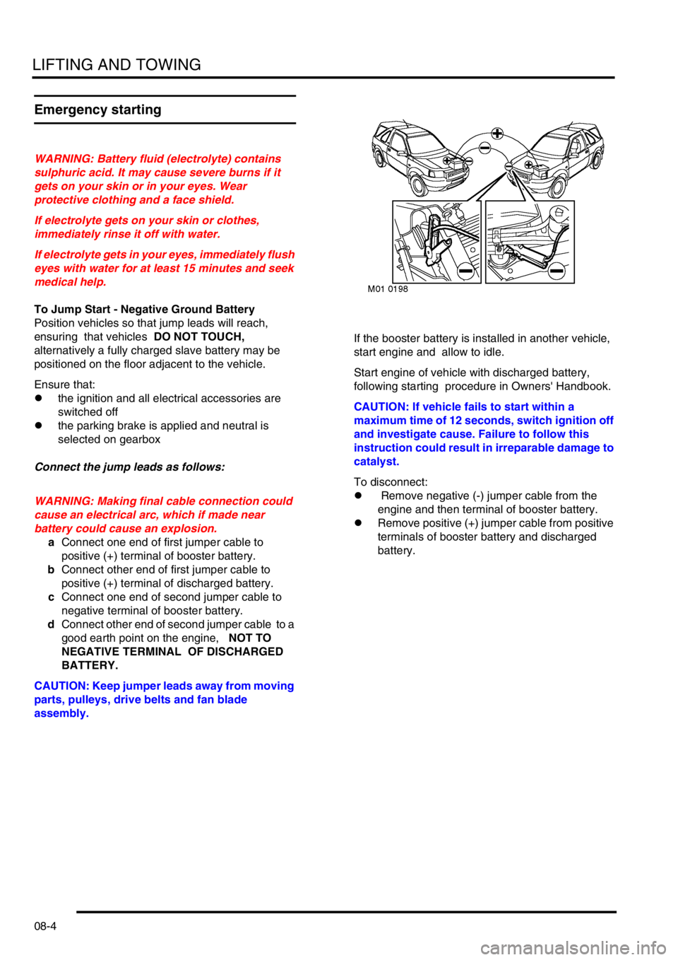
To Jump Start - Negative Ground Battery
Position vehicles so that jump leads will reach,
ensuring that vehicles DO NOT TOUCH,
alternatively a fully charged slave battery may be
positioned on the floor adjacent to the vehicle.
Ensure that:
lthe ignition and all electrical accessories are
switched off
lthe parking brake is applied and neutral is
selected on gearbox
Connect the jump leads as follows:
WARNING: Making final cable connection could
cause an electrical arc, which if made near
battery could cause an explosion.
aConnect one end of first jumper cable to
positive (+) terminal of booster battery.
bConnect other end of first jumper cable to
positive (+) terminal of discharged battery.
cConnect one end of second jumper cable to
negative terminal of booster battery.
dConnect other end of second jumper cable to a
good earth point on the engine, NOT TO
NEGATIVE TERMINAL OF DISCHARGED
BATTERY.
CAUTION: Keep jumper leads away from moving
parts, pulleys, drive belts and fan blade
assembly.If the booster battery is installed in another vehicle,
start engine and allow to idle.
Start engine of vehicle with discharged battery,
following starting procedure in Owners' Handbook.
CAUTION: If vehicle fails to start within a
maximum time of 12 seconds, switch ignition off
and investigate cause. Failure to follow this
instruction could result in irreparable damage to
catalyst.
To disconnect:
l Remove negative (-) jumper cable from the
engine and then terminal of booster battery.
lRemove positive (+) jumper cable from positive
terminals of booster battery and discharged
battery.
Page 176 of 1007

MAINTENANCE
MAINTENANCE 10-29
Gear Change and Parking Pawl Engagement –
(Automatic only, normal driving conditions)
1.Select 'R' and check for smooth take up.
2.Select 'D' and check for smooth up-changes of
ratio from rest.
3.Slow down vehicle and check for smooth down-
changes of ratio.
4.Stop vehicle on a slope.
5.Select 'P' and release handbrake.
6.Check that vehicle does not move and that
selector does not slip out of 'P'.
7.Carry out a similar check with vehicle facing in
the opposite direction.
Steering
1.With vehicle stationary, turn steering from lock
to lock. Check for smooth operation and ensure
there is no undue noise from the power steering
pump or drive belt.
Suspension
1.Check for noise, irregularity in ride (e.g.
dampers) and wheel imbalance.
Foot brake
1.Check for pedal effort, travel, braking
efficiency, pulling and binding.
Handbrake
1.Apply handbrake firmly, check travel and
ratchet hold and release.
Instruments
1.Check for correct operation of all instruments
and warning devices where practical.
Body
1.Check for abnormal body noise.
Seat Belts
1.Check for operation of inertia reels.Road Test
1.Drive vehicle on a short road test. Check all
vehicle systems for correct operation. Pay
particular attention to:
lEngine noise
lGearbox noise
lSuspension noise
lBody noise
lBraking system operation
lGear selection
lEngine performance
2.Where possible, check for correct operation of
Hill Descent Control (HDC) system. This should
not be carried out if excessive journey time is
required.
3.After road test, carry out a final inspection of the
vehicle on vehicle ramps.
4.Check all underbonnet fluid levels and top-up if
necessary.
Page 994 of 1007
DRIVER CONTROLS
REPAIRS 86-8-3
Sounder - parking aid - rear - from 04MY
$% 86.54.19
Remove
1. 3 door models: Remove RH rear lower quarter
trim casing.
+ INTERIOR TRIM COMPONENTS,
REPAIRS, Trim casing - rear quarter - lower
- 3 door.
2. 5 door models: Remove RH rear lower quarter
trim casing.
+ INTERIOR TRIM COMPONENTS,
REPAIRS, Trim casing - rear quarter - lower
- 5 door.
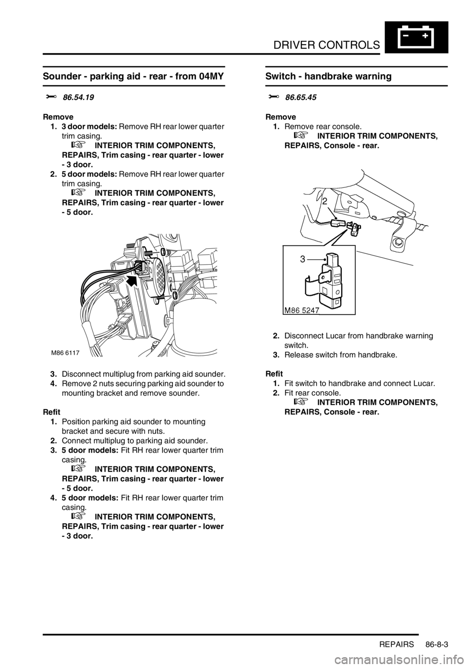
3.Disconnect multiplug from parking aid sounder.
4.Remove 2 nuts securing parking aid sounder to
mounting bracket and remove sounder.
Refit
1.Position parking aid sounder to mounting
bracket and secure with nuts.
2.Connect multiplug to parking aid sounder.
3. 5 door models: Fit RH rear lower quarter trim
casing.
+ INTERIOR TRIM COMPONENTS,
REPAIRS, Trim casing - rear quarter - lower
- 5 door.
4. 5 door models: Fit RH rear lower quarter trim
casing.
+ INTERIOR TRIM COMPONENTS,
REPAIRS, Trim casing - rear quarter - lower
- 3 door.
Switch - handbrake warning
$% 86.65.45
Remove
1.Remove rear console.
+ INTERIOR TRIM COMPONENTS,
REPAIRS, Console - rear.
2.Disconnect Lucar from handbrake warning
switch.
3.Release switch from handbrake.
Refit
1.Fit switch to handbrake and connect Lucar.
2.Fit rear console.
+ INTERIOR TRIM COMPONENTS,
REPAIRS, Console - rear.
M86 6117