relay LAND ROVER FREELANDER 2001 Workshop Manual
[x] Cancel search | Manufacturer: LAND ROVER, Model Year: 2001, Model line: FREELANDER, Model: LAND ROVER FREELANDER 2001Pages: 1007, PDF Size: 23.47 MB
Page 10 of 1007

CONTENTS
CONTENTS 7
FUEL DELIVERY SYSTEM - PETROL..................................................... 19-2-1
ADJUSTMENTS
Throttle cable - check and adjust - KV6 ......................................................................................... 19-2-1
Throttle cable - check and adjust - K1.8 ......................................................................................... 19-2-2
Fuel system - depressurise - KV6 - Non NAS ................................................................................. 19-2-2
Fuel system - depressurise - KV6 - NAS ....................................................................................... 19-2-3
Fuel system - depressurise - K1.8 .................................................................................................. 19-2-4
Fuel system - pressure test - KV6 - Non NAS................................................................................. 19-2-4
Fuel system - pressure test - KV6 - NAS ....................................................................................... 19-2-5
Fuel system - pressure test - K1.8 .................................................................................................. 19-2-5
Fuel tank - drain .............................................................................................................................. 19-2-6
REPAIRS
Air cleaner - K1.8 ............................................................................................................................ 19-2-7
Element - air cleaner - K1.8 ............................................................................................................ 19-2-8
Element - air cleaner - KV6 ............................................................................................................. 19-2-8
Element - air cleaner - KV6 - NAS ................................................................................................. 19-2-9
Cable - throttle - KV6 ...................................................................................................................... 19-2-10
Switch - inertia ................................................................................................................................ 19-2-11
Sensor - heated oxygen (H02S) - pre-catalyst - LH - KV6 - Non NAS ............................................ 19-2-12
Sensor - heated oxygen (H02S) - pre-catalyst - LH - KV6 - NAS .................................................. 19-2-13
Sensor - heated oxygen (H02S) - front - K1.8 ................................................................................ 19-2-14
Sensor - heated oxygen (H02S) - pre-catalyst - RH - KV6 - Non NAS ........................................... 19-2-15
Sensor - heated oxygen (H02S) pre-catalyst - RH - KV6 - NAS .................................................... 19-2-16
Sensor - mass air flow (MAF) - NAS .............................................................................................. 19-2-16
Relay - fuel pump ............................................................................................................................ 19-2-17
Throttle housing - K1.8 .................................................................................................................... 19-2-17
Throttle housing - KV6 - Non NAS .................................................................................................. 19-2-19
Throttle housing - KV6 - NAS ......................................................................................................... 19-2-22
Variable induction system (VIS) balance motor - KV6 .................................................................... 19-2-23
Sensor - heated oxygen (H02S) - post catalyst - LH - KV6 - Non NAS .......................................... 19-2-24
Sensor - heated oxygen (H02S) - post catalyst - LH - KV6 - NAS .................................................. 19-2-25
Sensor - heated oxygen (H02S) - post cat - K1.8 ........................................................................... 19-2-26
Sensor - heated oxygen (H02S) - post catalyst - RH - KV6 - NAS ................................................. 19-2-27
Filter - main ..................................................................................................................................... 19-2-28
Pump - fuel ...................................................................................................................................... 19-2-29
Tank - Non NAS .............................................................................................................................. 19-2-30
Tank - NAS ..................................................................................................................................... 19-2-32
Filler neck ........................................................................................................................................ 19-2-34
Fuel rail - KV6 - Non NAS ............................................................................................................... 19-2-35
Fuel rail - KV6 - NAS ...................................................................................................................... 19-2-36
Injector - KV6 .................................................................................................................................. 19-2-38
Injectors - set - K1.8 ........................................................................................................................ 19-2-39
Actuator unit - cruise control - KV6 - non NAS ................................................................................ 19-2-40
Vacuum pump - cruise control - KV6 - non NAS ............................................................................. 19-2-41
Switch - cruise control - KV6 - up to 04MY ..................................................................................... 19-2-41
Switch - engagement (on/off) - from 04MY .................................................................................... 19-2-42
Switch - multi-purpose ................................................................................................................... 19-2-42
ECU - cruise control - KV6 .............................................................................................................. 19-2-43
Interface ECU - cruise control - KV6 ............................................................................................... 19-2-43
Page 21 of 1007

CONTENTS
18 CONTENTS
HEATING AND VENTILATION ................................................................. 80-1
REPAIRS
Controls - heater - up to 04MY ....................................................................................................... 80-1
Controls - heater - from 04MY ........................................................................................................ 80-2
Servo - air recirculation .................................................................................................................. 80-3
Switch - recirculation control .......................................................................................................... 80-3
Switch - fan - front heater .............................................................................................................. 80-4
Ventilator - face level - LH ............................................................................................................. 80-5
Plenum - air intake ......................................................................................................................... 80-6
Heater unit ..................................................................................................................................... 80-7
Element - positive temperature co-efficient (PTC) heater - Td4 models......................................... 80-10
Harness - positive temperature co-efficient (PTC) heater - Td4 models ........................................ 80-11
Microswitch - positive temperature co-efficient (PTC) heater - Td4 models ................................... 80-14
Blower assembly ............................................................................................................................ 80-14
Resistor unit - fan motor ................................................................................................................ 80-15
Matrix - heater................................................................................................................................. 80-15
Relay - power - positive temperature co-efficient (PTC) - Td4 models ........................................... 80-16
Relay - control - positive temperature co-efficient (PTC) - Td4 models .......................................... 80-17
Fuel burning heater (FBH) .............................................................................................................. 80-18
Sensor - outside temperature (OT) ................................................................................................. 80-19
Fuel pump - fuel burning heater - up to 03MY ................................................................................ 80-20
Fuel pump - fuel burning heater - from 03MY ................................................................................. 80-21
AIR CONDITIONING ................................................................................. 82-1
REFRIGERANT RECOVERY, RECYCLING AND RECHARGING
Refrigerant recovery - recycling and recharge................................................................................ 82-1
ADJUSTMENTS
Drive belt - compressor - Td4 ......................................................................................................... 82-3
REPAIRS
Drive belt - compressor - Td4 ......................................................................................................... 82-5
Compressor - Td4 ........................................................................................................................... 82-6
Compressor - KV6 .......................................................................................................................... 82-7
Compressor - K1.8.......................................................................................................................... 82-8
Condenser ...................................................................................................................................... 82-10
Receiver drier ................................................................................................................................. 82-12
Switch - control ............................................................................................................................... 82-13
Sensor - refrigerant pressure .......................................................................................................... 82-14
Valve - thermostatic expansion (TXV) ............................................................................................ 82-15
Evaporator ..................................................................................................................................... 82-16
Page 22 of 1007

CONTENTS
CONTENTS 19
WIPERS AND WASHERS ........................................................................ 84-1
REPAIRS
Reservoir - washer ......................................................................................................................... 84-1
Jet - washer - each ........................................................................................................................ 84-2
Pump - washer ............................................................................................................................... 84-2
Arm - wiper - each .......................................................................................................................... 84-3
Blade - wiper - each ....................................................................................................................... 84-3
Motor & linkage - wiper .................................................................................................................. 84-4
Switch - wiper/washer .................................................................................................................... 84-4
Pump - washer ............................................................................................................................... 84-5
Arm - wiper ..................................................................................................................................... 84-5
Blade - wiper .................................................................................................................................. 84-6
Motor - wiper .................................................................................................................................. 84-7
Switch - combined wiper/washer ................................................................................................... 84-8
Relay - tailgate wipe - 5 door ......................................................................................................... 84-8
CHARGING AND STARTING ................................................................... 86-1-1
ADJUSTMENTS
Ancillary drive belt - K1.8 ............................................................................................................... 86-1-1
Ancillary drive belt - K1.8 with A/C .................................................................................................. 86-1-2
REPAIRS
Alternator - Td4 ............................................................................................................................... 86-1-3
Alternator - KV6 .............................................................................................................................. 86-1-5
Alternator - K1.8 .............................................................................................................................. 86-1-6
Ancillary drive belt - Td4 ................................................................................................................. 86-1-7
Ancillary drive belt - K1.8 without A/C ............................................................................................. 86-1-8
Ancillary drive belt - K1.8 with A/C .................................................................................................. 86-1-9
Ancillary drive belt - KV6 ................................................................................................................. 86-1-10
Tensioner - ancillary drive belt - Td4 ............................................................................................... 86-1-11
Battery ............................................................................................................................................. 86-1-12
Carrier - battery ............................................................................................................................... 86-1-13
Relay - main .................................................................................................................................... 86-1-14
Starter motor - Td4 .......................................................................................................................... 86-1-15
Starter motor - KV6 ......................................................................................................................... 86-1-16
Starter motor - K1.8 ........................................................................................................................ 86-1-17
Relay - starter ................................................................................................................................. 86-1-18
Page 23 of 1007

CONTENTS
20 CONTENTS
LIGHTING.................................................................................................. 86-2-1
ADJUSTMENTS
Headlamps - pair - align beam - up to 04MY .................................................................................. 86-2-1
Headlamps - pair - align beam - from 04MY ................................................................................... 86-2-1
REPAIRS
Headlamp assembly - up to 04MY.................................................................................................. 86-2-3
Headlamp assembly - from 04MY .................................................................................................. 86-2-4
Lamp assembly - flasher side repeater - front ................................................................................ 86-2-5
Lamp assembly - tail ....................................................................................................................... 86-2-5
Lamp assembly - number plate ...................................................................................................... 86-2-6
Lamp assembly - fog/driving - from 04MY ...................................................................................... 86-2-6
Lamp assembly - rear ..................................................................................................................... 86-2-7
Lamp assembly - centre high mounted stop (CHMSL) ................................................................... 86-2-7
Lamp assembly - glove compartment ............................................................................................. 86-2-8
Lamp assembly - load space .......................................................................................................... 86-2-8
Switch - headlamp levelling ............................................................................................................ 86-2-9
Switch - glove compartment ........................................................................................................... 86-2-9
Switch - hazard warning ................................................................................................................. 86-2-10
Switch - combined direction indicator/headlight/horn ..................................................................... 86-2-10
Switch - rear fog lamp ..................................................................................................................... 86-2-11
CONTROL UNITS ..................................................................................... 86-3-1
REPAIRS
Control unit - window lift ................................................................................................................. 86-3-1
Relay - power folding mirrors - from 02MY ..................................................................................... 86-3-1
Central Control Unit (CCU) ............................................................................................................. 86-3-2
Control Unit - power fold mirrors - up to 02MY ............................................................................... 86-3-3
SECURITY................................................................................................. 86-4-1
REPAIRS
Solenoid/motor - taildoor................................................................................................................. 86-4-1
Switch/push - horn .......................................................................................................................... 86-4-2
Horn ................................................................................................................................................ 86-4-2
Immobilisation - electronic control unit (ECU) - ............................................................................. 86-4-3
Sensor - volumetric - alarm system - 3 door ................................................................................... 86-4-3
Module (ECU) - volumetric - alarm system - 5 door - without sunroof ........................................... 86-4-5
Module (ECU) - volumetric - alarm system - 5 door - with sunroof ................................................ 86-4-7
Receiver - alarm system ................................................................................................................. 86-4-10
Coil - passive immobilisation - alarm system .................................................................................. 86-4-10
Page 24 of 1007

CONTENTS
CONTENTS 21
WINDOWS ................................................................................................ 86-5-1
REPAIRS
Motor & control unit - front door - 3 door ......................................................................................... 86-5-1
Motor & control unit - front door - 5 door ......................................................................................... 86-5-2
Switch - master window - 5 door - from 04MY ................................................................................ 86-5-2
Relay - control - tail door glass ....................................................................................................... 86-5-3
Microswitch - hardtop sensing - 3 door ........................................................................................... 86-5-4
Relay - heated front screen ........................................................................................................... 86-5-5
Switch - backlight heater ................................................................................................................. 86-5-6
IN CAR ENTERTAINMENT ...................................................................... 86-6-1
REPAIRS
Radio - up to 04MY ......................................................................................................................... 86-6-1
Radio/CD - from 04MY .................................................................................................................... 86-6-2
Speaker - rear - 3 door .................................................................................................................... 86-6-3
Speaker - rear - 5 door .................................................................................................................... 86-6-3
Speaker - front ................................................................................................................................ 86-6-4
Aerial - manual - 3 door .................................................................................................................. 86-6-4
Aerial - manual - 5 door .................................................................................................................. 86-6-5
Coaxial lead - front aerial - 3 door ................................................................................................... 86-6-6
Coaxial lead - front aerial - 5 door ................................................................................................... 86-6-7
Speaker - tweeter - front ................................................................................................................. 86-6-8
Speaker - tweeter - rear - 3 door ..................................................................................................... 86-6-9
Amplifier - power ............................................................................................................................ 86-6-10
Sub-woofer assembly .................................................................................................................... 86-6-11
Coaxial lead - extension.................................................................................................................. 86-6-12
HARNESSES ............................................................................................ 86-7-1
REPAIRS
Fuse box - passenger compartment ............................................................................................... 86-7-1
Harness - main ................................................................................................................................ 86-7-2
Harness - tailgate ............................................................................................................................ 86-7-12
Harness - interior lights - 5 door ...................................................................................................... 86-7-15
Harness - front door - 5 door ........................................................................................................... 86-7-15
Harness - rear door ......................................................................................................................... 86-7-16
DRIVER CONTROLS ................................................................................ 86-8-1
REPAIRS
Switch - remote control - audio system .......................................................................................... 86-8-1
Switch - park distance control (PDC) - from 04 MY ........................................................................ 86-8-1
Control unit (ECU) - parking aid - from 04MY ................................................................................. 86-8-2
Sensor - parking aid - rear - from 04MY ......................................................................................... 86-8-2
Sounder - parking aid - rear - from 04MY ....................................................................................... 86-8-3
Switch - handbrake warning ............................................................................................................ 86-8-3
Switch - hazard warning - from 04MY ............................................................................................. 86-8-4
Cigar lighter - front .......................................................................................................................... 86-8-4
Switch - control - exterior mirror ...................................................................................................... 86-8-5
Page 51 of 1007

GENERAL INFORMATION
03-20
Disciplines
Switch off the ignition prior to making any connection
or disconnection in the system, to prevent electrical
surges caused by disconnecting 'live' connections
damaging electronic components.
Ensure hands and work surfaces are clean and free
of grease, swarf, etc. Grease collects dirt which can
cause electrical tracking (short-circuits) or high-
resistance contacts.
When handling printed circuit boards, treat with care
and hold by the edges only; note that some electronic
components are susceptible to body static.
Connectors should never be subjected to forced
removal or refit, especially inter-board connectors.
Damaged contacts can cause short-circuit and
open-circuit fault conditions.
Prior to commencing test, and periodically during a
test, touch a good vehicle body earth to discharge
static charge. Some electronic components are
vulnerable to the static electricity that may be
generated by the operator.
Grease for electrical connectors
Some under bonnet and under body connectors may
be protected against corrosion by the application of a
special grease during vehicle production. Should
connectors be disturbed in service, or repaired or
replaced, additional grease should be re-applied:
Part No. BAU 5811, available in 150 gm tubs.
NOTE: The use of greases other than BAU 5811
must be avoided as they can migrate into relays,
switches etc. contaminating the contacts and leading
to intermittent operation or failure.
Supplementary restraint system
precautions
General
The Supplementary Restraint System (SRS)
provides active protection for vehicle occupants in
the event of a serious collision. The system
components include airbags and pre-tensioner seat
belts which are automatically deployed when a
severe frontal crash condition is detected.
The SRS pyrotechnic components could be
potentially hazardous to the service engineer if not
handled correctly. The following guidelines are
intended to alert the service engineer to potential
sources of danger and emphasise the importance of
ensuring the integrity of SRS components fitted to
the vehicle.
In order to assure system integrity, it is essential that
the SRS system is regularly checked and maintained
so that it is ready for operation in the event of an
accident.
Where necessary, additional specific precautions are
detailed in the relevant sections of this Manual which
should be referred to prior to commencing repair
operations.
WARNING: Always follow the 'SRS Precautions'
and the correct procedures for working on SRS
components. Persons working on SRS systems
must be fully trained and have been issued with
copies of the Safety guidelines.
WARNING: It is imperative that before any work
is undertaken on the SRS system the appropriate
information is read thoroughly.
WARNING: The airbag module contains sodium
azide which is poisonous and extremely
flammable. Contact with water, acid or heavy
metals may produce harmful or explosive
compounds. Do not dismantle, incinerate or
bring into contact with electricity, before the unit
has been deployed.
WARNING: Always replace a seat belt assembly
that has withstood the strain of a severe vehicle
impact, or if the webbing shows signs of fraying.
WARNING: Always disconnect the vehicle
battery before carrying out any electric welding
on a vehicle fitted with an SRS system.
CAUTION: Do not expose an airbag module or
seat belt pre-tensioner to heat exceeding 85º C
(185º F).
Page 213 of 1007

ENGINE - K SERIES KV6
12-3-36 REPAIRS
17.Rotate heated front screen relay anti-clockwise
and release it from 'E' box bracket.
18.Release 4 clips and remove carrier from 'E' box.
19.Remove nut, release retainer and remove 'E'
box.20.Remove engine compartment fuse box cover.
21.Remove 2 bolts securing battery and starter
lead to fuse box.
22.Disconnect multiplug from fuse box.
23.Disconnect earth header multiplug.
24.Release 3 clips securing engine harness to 'E'
box mounting bracket, lay harness over engine.
M12 6765
M12 6766
Page 338 of 1007

FUEL DELIVERY SYSTEM - PETROL
REPAIRS 19-2-17
Relay - fuel pump
$% 19.22.39
Remove
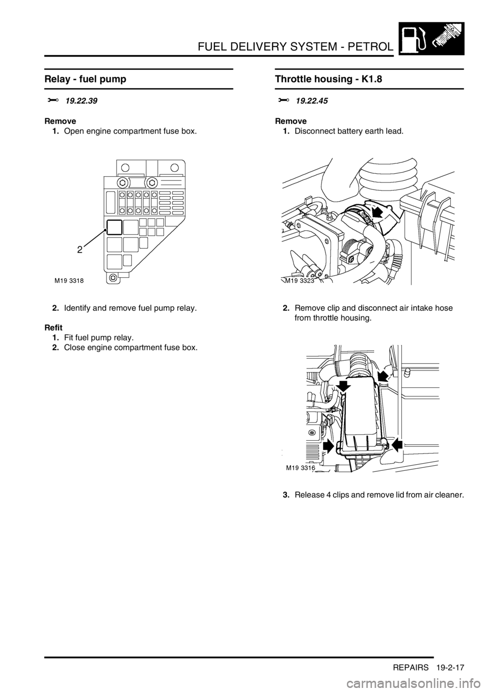
1.Open engine compartment fuse box.
2.Identify and remove fuel pump relay.
Refit
1.Fit fuel pump relay.
2.Close engine compartment fuse box.
Throttle housing - K1.8
$% 19.22.45
Remove
1.Disconnect battery earth lead.
2.Remove clip and disconnect air intake hose
from throttle housing.
3.Release 4 clips and remove lid from air cleaner.
Page 794 of 1007

PANEL REPAIRS
REPAIRS 77-2-39
Valance outer reinforcement
Remove
1.Disconnect battery earth lead.
2.Disconnect alternator.
3.Disconnect all ECUs.
4.Remove road wheel(s).
5.Remove front wheel arch liner.
+ EXTERIOR FITTINGS, REPAIRS,
Liner - front wheel arch.
6.Remove front wing.
+ EXTERIOR FITTINGS, REPAIRS,
Wing - front.
7.Remove front bumper valance.
+ EXTERIOR FITTINGS, REPAIRS,
Bumper - assembly - front - up to 04MY.
8.Remove headlamp.
+ LIGHTING, REPAIRS, Headlamp
assembly - up to 04MY.
9.Release wiring from valance and position
aside.
10. LH side: Remove battery.
+ CHARGING AND STARTING,
REPAIRS, Battery.
11. LH side: Remove ECM.
12. LH side: Remove relay module.
13. LH side: Remove battery carrier.
+ CHARGING AND STARTING,
REPAIRS, Carrier - battery.
14. LH side: Remove engine compartment fuse
box and related wiring.
15. RH side: Remove PAS fluid reservoir.
16. RH side: Remove brake pipes from valance. Repair
1.Remove existing panel(s), prepare panel joint
faces and install new panel(s) in accordance
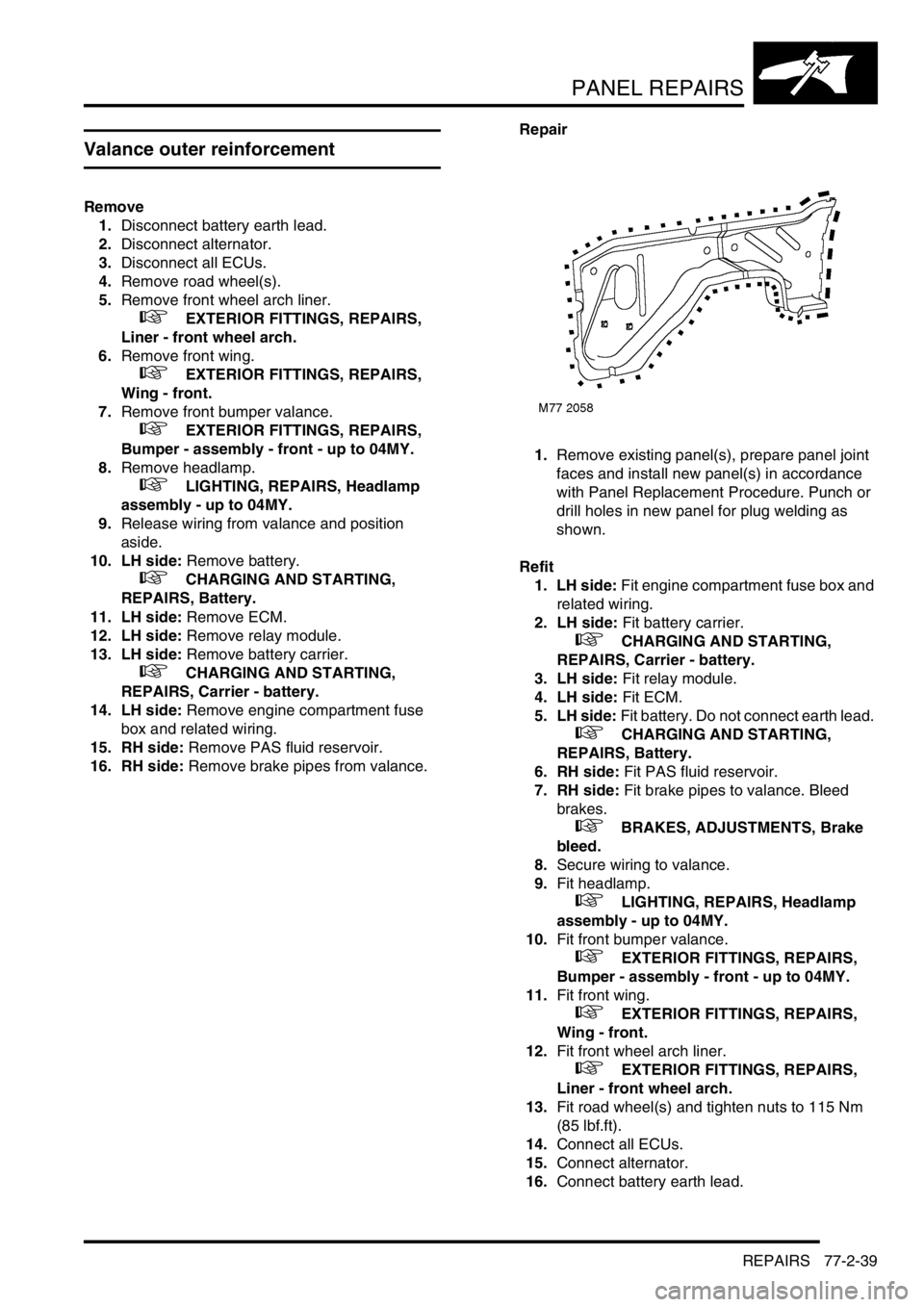
with Panel Replacement Procedure. Punch or
drill holes in new panel for plug welding as
shown.
Refit
1. LH side: Fit engine compartment fuse box and
related wiring.
2. LH side: Fit battery carrier.
+ CHARGING AND STARTING,
REPAIRS, Carrier - battery.
3. LH side: Fit relay module.
4. LH side: Fit ECM.
5. LH side: Fit battery. Do not connect earth lead.
+ CHARGING AND STARTING,
REPAIRS, Battery.
6. RH side: Fit PAS fluid reservoir.
7. RH side: Fit brake pipes to valance. Bleed
brakes.
+ BRAKES, ADJUSTMENTS, Brake
bleed.
8.Secure wiring to valance.
9.Fit headlamp.
+ LIGHTING, REPAIRS, Headlamp
assembly - up to 04MY.
10.Fit front bumper valance.
+ EXTERIOR FITTINGS, REPAIRS,
Bumper - assembly - front - up to 04MY.
11.Fit front wing.
+ EXTERIOR FITTINGS, REPAIRS,
Wing - front.
12.Fit front wheel arch liner.
+ EXTERIOR FITTINGS, REPAIRS,
Liner - front wheel arch.
13.Fit road wheel(s) and tighten nuts to 115 Nm
(85 lbf.ft).
14.Connect all ECUs.
15.Connect alternator.
16.Connect battery earth lead.
Page 872 of 1007

HEATING AND VENTILATION
REPAIRS 80-7
Heater unit
$% 80.20.01
Remove
1.Drain cooling system.
+ COOLING SYSTEM - Td4,
ADJUSTMENTS, Coolant - drain and refill.
+ COOLING SYSTEM - K SERIES 1.8,
ADJUSTMENTS, Coolant - drain & refill.
+ COOLING SYSTEM - K SERIES KV6,
ADJUSTMENTS, Coolant - drain and refill.
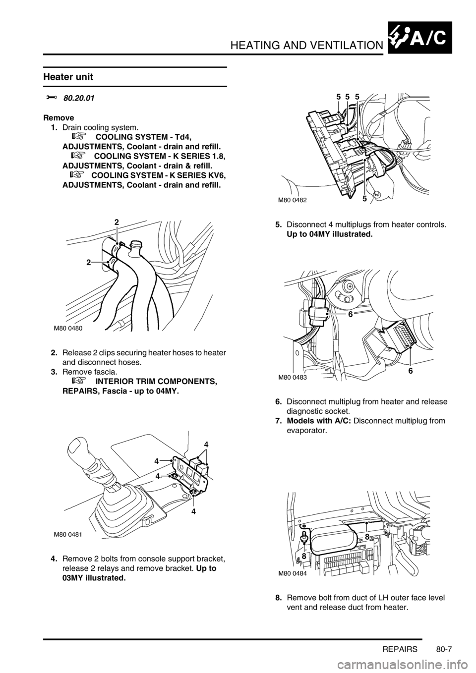
2.Release 2 clips securing heater hoses to heater
and disconnect hoses.
3.Remove fascia.
+ INTERIOR TRIM COMPONENTS,
REPAIRS, Fascia - up to 04MY.
4.Remove 2 bolts from console support bracket,
release 2 relays and remove bracket. Up to
03MY illustrated.5.Disconnect 4 multiplugs from heater controls.
Up to 04MY illustrated.
6.Disconnect multiplug from heater and release
diagnostic socket.
7. Models with A/C: Disconnect multiplug from
evaporator.
8.Remove bolt from duct of LH outer face level
vent and release duct from heater.