ECU Lexus ES300h 2020 Repair Manual
[x] Cancel search | Manufacturer: LEXUS, Model Year: 2020, Model line: ES300h, Model: Lexus ES300h 2020Pages: 462, PDF Size: 9.98 MB
Page 394 of 462
3927-2. Steps to take in an emergency
6Open and close any of the doors of
your vehicle with the power switch
off.
7 Maintain the engine speed of the
second vehicle and start the hybrid
system of your vehicle by turning
the power switch to ON mode.
8 Make sure the “READY” indicator
comes on. If the indicator does not
come on, contact your Lexus
dealer.
9 Once the vehicle’s hybrid system
has started, remove the jumper
cables in the exact reverse order
from which they were connected.
10 Close the exclusive jump starting
terminal cover, and reinstall the fuse
box cover to its original position.
Once the hybrid system starts, have the
vehicle inspected at your Lexus dealer as
soon as possible.
■Starting the hybrid system when the 12-
volt battery is discharged
The hybrid system cannot be started by
push-starting.
■To prevent 12-volt battery discharge
●Turn off the headlights and the audio sys-
tem while the hybrid system is stopped.
●Turn off any unnecessary electrical com-
ponents when the vehicle is running at a
low speed for an extended period, such
as in heavy traffic.
■When the 12-volt battery is removed or
discharged
●Information stored in the ECU is cleared.
When the 12-volt battery is depleted,
have the vehicle inspected at your Lexus
dealer.
●Some systems may require initialization.
( P.429)
■When removing the 12-volt battery ter-
minals
When the 12-volt battery terminals are
removed, the information stored in the
ECU is cleared. Before removing the 12-
volt battery terminals, contact your Lexus
dealer.
■Charging the 12-volt battery
The electricity stored in the 12-volt battery
will discharge gradually even when the
vehicle is not in use, due to natural dis-
charge and the draining effects of certain
electrical appliances. If the vehicle is left for
a long time, the 12-volt battery may dis-
charge, and the hybrid system may be
unable to start. (The 12-volt battery
recharges automatically while the hybrid
system is operating.)
■When recharging or replacing the 12-
volt battery
●In some cases, it may not be possible to
unlock the doors using the smart access
system with push-button start when the
12-volt battery is discharged. Use the
wireless remote control or the mechani-
cal key to lock or unlock the doors.
●The hybrid system may not start on the
first attempt after the 12-volt battery has
recharged but will start normally after the
second attempt. This is not a malfunction.
●The power switch mode is memorized by
the vehicle. When the 12-volt battery is
reconnected, the system will return to the
mode it was in before the 12-volt battery
was discharged. Before disconnecting
the 12-volt battery, turn the power switch
off.
If you are unsure what mode the power
switch was in before the 12-volt battery
discharged, be especially careful when
reconnecting the 12-volt battery.
■When replacing the 12-volt battery
●Use a 12-volt battery that conforms to
European regulations.
●Use a 12-volt battery that the case size is
same as the previous one (LN2), 20 hour
rate capacity (20HR) is equivalent
(60Ah) or greater, and performance rat-
ing (CCA) is equivalent (345A) or
greater.
Page 395 of 462
3937-2. Steps to take in an emergency
7
When trouble arises
• If the sizes differ, the 12-volt battery can-not be properly secured.
• 12-volt battery performance may decrease and the hybrid system may not
be able to start.
• If the 20 hour rate capacity is low, even if the time period where the vehicle is not
used is a short time, the 12-volt battery
may discharge and hybrid system may
not be able to start.
●Use a 12-volt battery with a handle. If a
12-volt battery without a handle is used,
removal is more difficult.
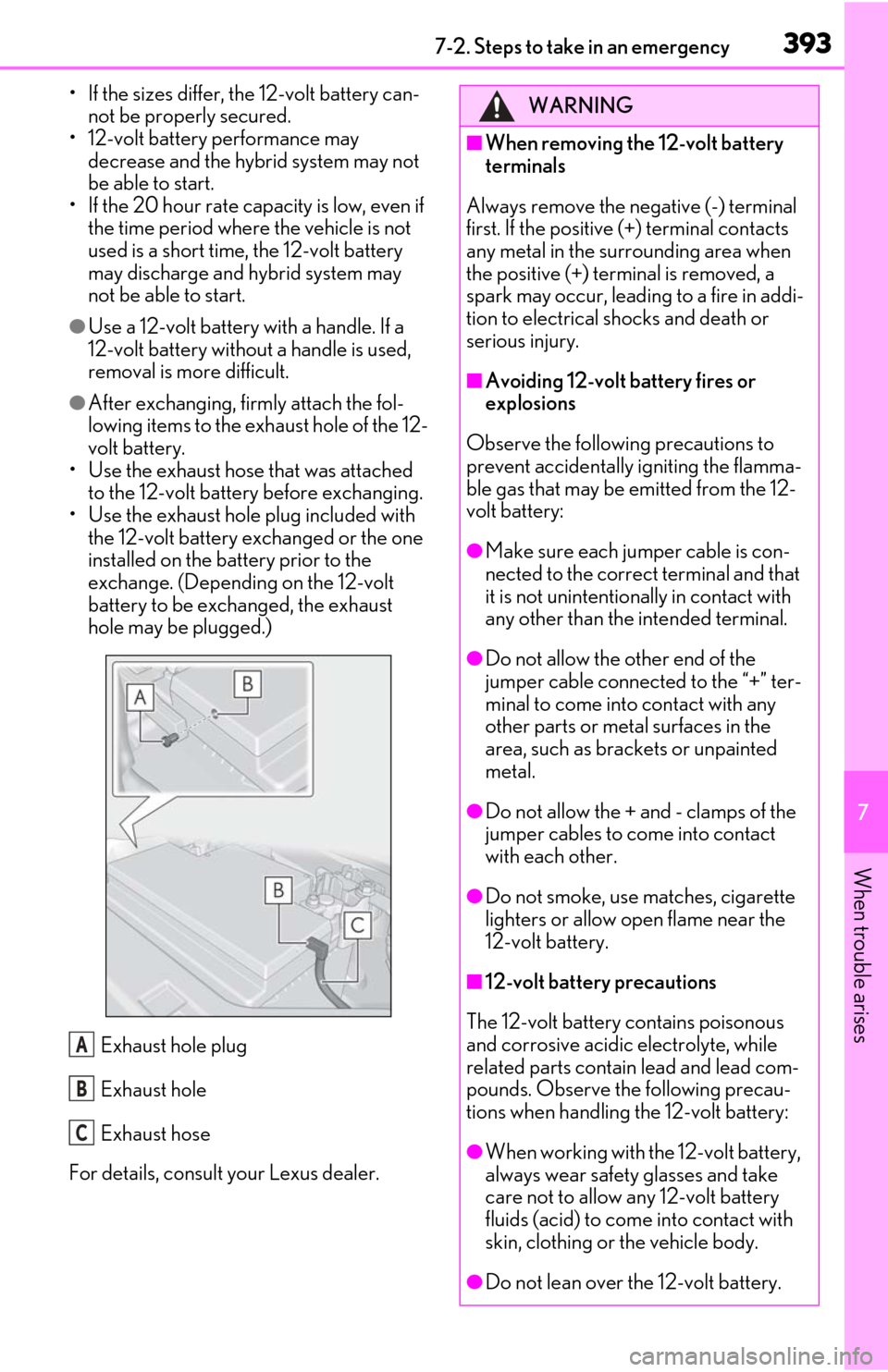
●After exchanging, firmly attach the fol-
lowing items to the exhaust hole of the 12-
volt battery.
• Use the exhaust hose that was attached
to the 12-volt battery before exchanging.
• Use the exhaust hole plug included with the 12-volt battery exchanged or the one
installed on the battery prior to the
exchange. (Depending on the 12-volt
battery to be exchanged, the exhaust
hole may be plugged.)
Exhaust hole plug
Exhaust hole
Exhaust hose
For details, consult your Lexus dealer.
A
B
C
WARNING
■When removing the 12-volt battery
terminals
Always remove the negative (-) terminal
first. If the positive (+) terminal contacts
any metal in the surrounding area when
the positive (+) terminal is removed, a
spark may occur, leading to a fire in addi-
tion to electrical shocks and death or
serious injury.
■Avoiding 12-volt battery fires or
explosions
Observe the following precautions to
prevent accidentally igniting the flamma-
ble gas that may be emitted from the 12-
volt battery:
●Make sure each jumper cable is con-
nected to the correct terminal and that
it is not unintentiona lly in contact with
any other than the intended terminal.
●Do not allow the other end of the
jumper cable connected to the “+” ter-
minal to come into contact with any
other parts or metal surfaces in the
area, such as brackets or unpainted
metal.
●Do not allow the + and - clamps of the
jumper cables to come into contact
with each other.
●Do not smoke, use matches, cigarette
lighters or allow open flame near the
12-volt battery.
■12-volt battery precautions
The 12-volt battery contains poisonous
and corrosive acidic electrolyte, while
related parts contain lead and lead com-
pounds. Observe the following precau-
tions when handling the 12-volt battery:
●When working with the 12-volt battery,
always wear safety glasses and take
care not to allow any 12-volt battery
fluids (acid) to come into contact with
skin, clothing or the vehicle body.
●Do not lean over the 12-volt battery.
Page 396 of 462
3947-2. Steps to take in an emergency
WARNING
●In the event that 12-volt battery fluid
comes into contact with the skin or
eyes, immediately wash the affected
area with water and seek medical
attention.
Place a wet sponge or cloth over the
affected area until medical attention
can be received.
●Always wash your hands after handling
the 12-volt battery support, terminals,
and other battery-related parts.
●Do not allow children near the 12-volt
battery.
■After recharging the 12-volt battery
Have the 12-volt battery inspected at
your Lexus dealer as soon as possible. If
the 12-volt battery is deteriorating, con-
tinued use may cause the 12-volt battery
to emit a malodorous gas, which may be
detrimental to the health of passengers.
■When exchanging the 12-volt battery
●When the vent plug and indicator are
close to the hold down clamp, the bat-
tery fluid (sulfuric acid) may leak.
●After exchanging, securely attach the
exhaust hose and exhaust hole plug to
the exhaust hole of the exchanged 12-
volt battery. If not properly installed,
gases (hydrogen) may leak into the
vehicle interior, and there is the possi-
ble danger of the gas igniting and
exploding.
NOTICE
■When handling jumper cables
When connecting the jumper cables,
ensure that they do not become entan-
gled in the cooling fan or engine drive
belt.
■To prevent damaging the vehicle
The exclusive jump starting terminal is to
be used when charging the 12-volt bat-
tery from another vehicle in an emer-
gency. It cannot be used to jump start
another vehicle.
Page 419 of 462
4178-1. Specifications
8
Vehicle specifications
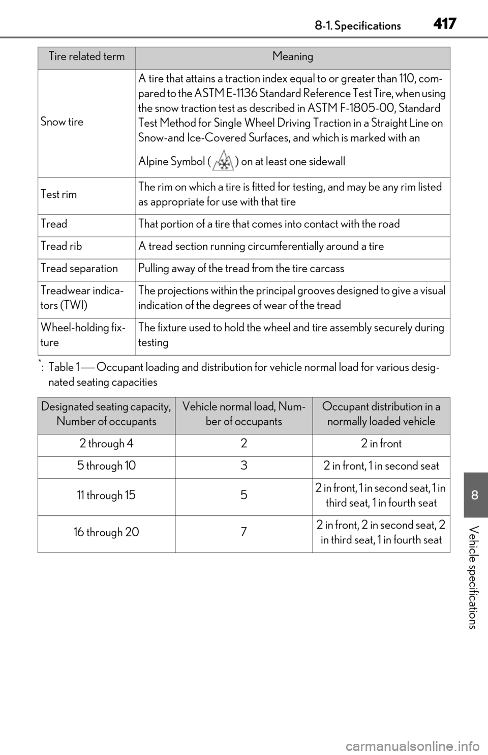
*:Table 1 Occupant loading and distribution for vehicle normal load for various desig-
nated seating capacities
Snow tire
A tire that attains a traction index equal to or greater than 110, com-
pared to the ASTM E-1136 Standard Reference Test Tire, when using
the snow traction test as described in ASTM F-1805-00, Standard
Test Method for Single Wheel Driving Traction in a Straight Line on
Snow-and Ice-Covered Surfaces, and which is marked with an
Alpine Symbol ( ) on at least one sidewall
Test rimThe rim on which a tire is fitted fo r testing, and may be any rim listed
as appropriate for use with that tire
TreadThat portion of a tire that comes into contact with the road
Tread ribA tread section running circumferentially around a tire
Tread separationPulling away of the tread from the tire carcass
Treadwear indica-
tors (TWI)The projections within th e principal grooves designed to give a visual
indication of the degree s of wear of the tread
Wheel-holding fix-
tureThe fixture used to hold the wheel and tire assembly securely during
testing
Designated seating capacity,
Number of occupantsVehicle normal load, Num- ber of occupantsOccupant distribution in a normally loaded vehicle
2 through 422 in front
5 through 1032 in front, 1 in second seat
11 through 1552 in front, 1 in second seat, 1 in
third seat, 1 in fourth seat
16 through 2072 in front, 2 in second seat, 2 in third seat, 1 in fourth seat
Tire related termMeaning
Page 423 of 462

4218-2. Customization
8
Vehicle specifications
■Smart access system with push-button start and wireless remote control
( P.99, 110)
■Smart access system with push-button start ( P.99, 110)
■Wireless remote control ( P.96, 99, 103)
FunctionDefault settingCustomized set-
ting
Operating signal (Buzzers)5OffOO1 to 7
Operation signal (Emergency
flashers)OnOffOO
Time elapsed before automatic
door lock function is activated if
door is not opened after being
unlocked
60 seconds
Off
OO30 seconds
120 seconds
Open door warning buzzerOnOffO
FunctionDefault settingCustomized set-ting
Smart access system with push-
button startOnOffO
Smart door unlockingDriver’s doorAll the doorsOO
Time elapsed before unlocking
all the door when gripping and
holding the driver’s door handle
2 seconds
Off
O1.5 seconds
2.5 seconds
Number of consecutive door
lock operations2 timesAs many as desiredO
FunctionDefault settingCustomized set-ting
Wireless remote controlOnOffO
Unlocking operation
Driver’s door
unlocked in one step, all doors
unlocked in two step
All doors unlocked in one stepOO
ABC
ABC
ABC
Page 434 of 462
4329-1. For owners
9-1.For owners
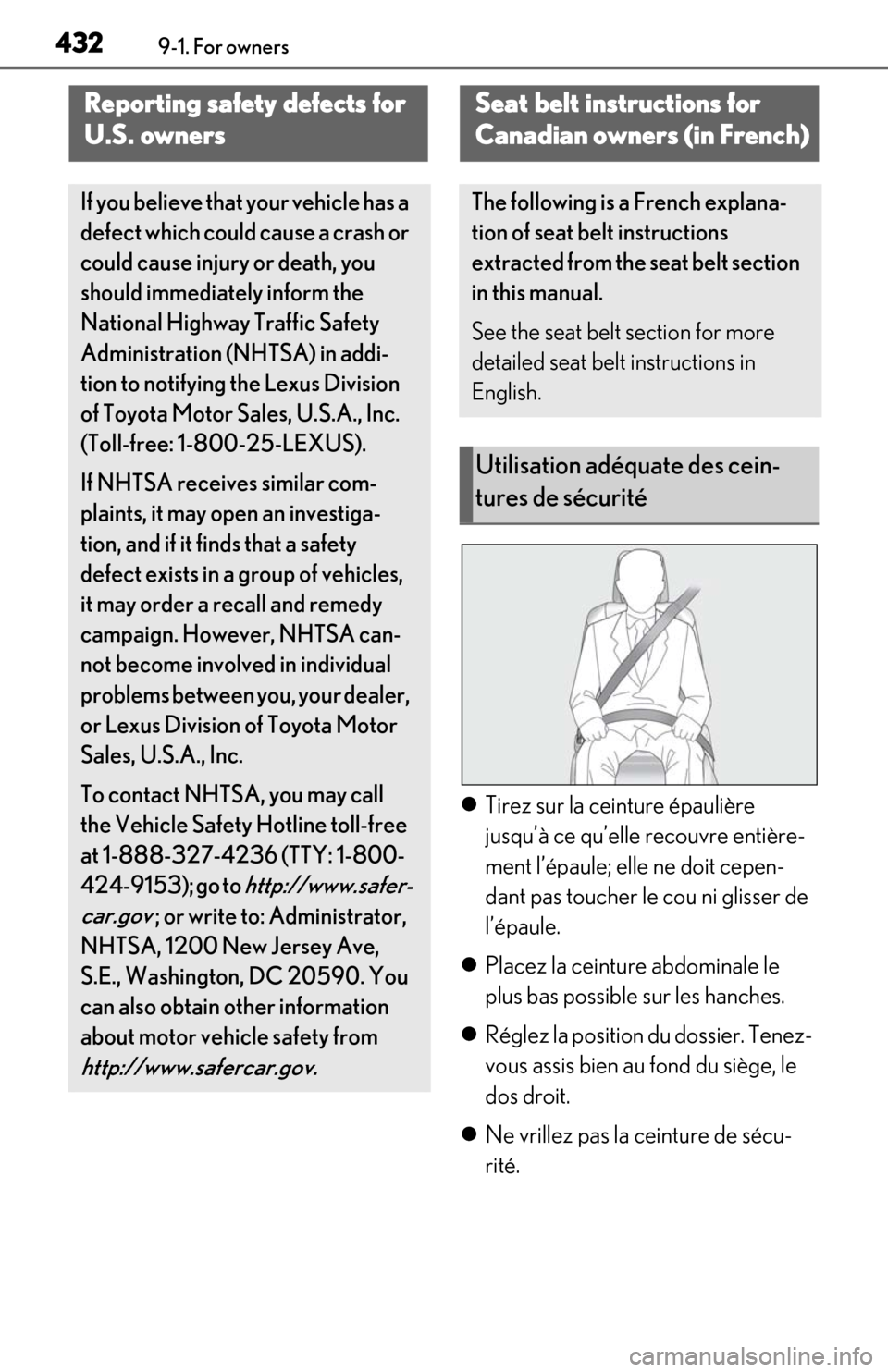
Tirez sur la ceinture épaulière
jusqu’à ce qu’elle recouvre entière-
ment l’épaule; elle ne doit cepen-
dant pas toucher le cou ni glisser de
l’épaule.
Placez la ceinture abdominale le
plus bas possible sur les hanches.
Réglez la position du dossier. Tenez-
vous assis bien au fond du siège, le
dos droit.
Ne vrillez pas la ceinture de sécu-
rité.
Reporting safety defects for
U.S. owners
If you believe that your vehicle has a
defect which could cause a crash or
could cause injury or death, you
should immediately inform the
National Highway Traffic Safety
Administration (NHTSA) in addi-
tion to notifying the Lexus Division
of Toyota Motor Sa les, U.S.A., Inc.
(Toll-free: 1-800-25-LEXUS).
If NHTSA receives similar com-
plaints, it may open an investiga-
tion, and if it finds that a safety
defect exists in a group of vehicles,
it may order a recall and remedy
campaign. However, NHTSA can-
not become involved in individual
problems between you, your dealer,
or Lexus Division of Toyota Motor
Sales, U.S.A., Inc.
To contact NHTS A, you may call
the Vehicle Safety Hotline toll-free
at 1-888-327-4236 (TTY: 1-800-
424-9153); go to
http://www.safer-
car.gov
; or write to: Administrator,
NHTSA, 1200 New Jersey Ave,
S.E., Washington, DC 20590. You
can also obtain other information
about motor vehicle safety from
http://www.safercar.gov.
Seat belt instructions for
Canadian owners (in French)
The following is a French explana-
tion of seat belt instructions
extracted from the seat belt section
in this manual.
See the seat belt section for more
detailed seat belt instructions in
English.
Utilisation adéquate des cein-
tures de sécurité
Page 435 of 462
4339-1. For owners
9
For owners
■Manipulation des ceintures de
sécurité
Avec un chiffon ou une éponge, net-
toyez à l’aide d’un savon doux et de
l’eau tiède. Vérifiez aussi les ceintures
régulièrement pour vous assurer
qu’elles ne présentent pas d’usure
excessive, d’effilochage ou de cou-
pures.
Entretien et soin
AVERTISSEMENT
■Dommages et usure de la ceinture de
sécurité
Vérifiez périodiquement le système de
ceintures de sécurité. Vérifiez qu’il n’y a
pas de coupures, d’effilochures ni de
pièces desserrées. N’utilisez pas une
ceinture de sécurité endommagée avant
qu’elle ne soit remp lacée. Les ceintures
de sécurité endommagées ne peuvent
pas protéger les occupants contre les
blessures graves, voire mortelles.
Page 437 of 462
4359-1. For owners
9
For owners
Coussins gonflables SRS en rideau
• Peuvent aider à protéger principalement la tête des occupants des sièges latéraux
• Peuvent aider à empêcher les occupants d’être éjectés du véhicule en cas de tonneaux
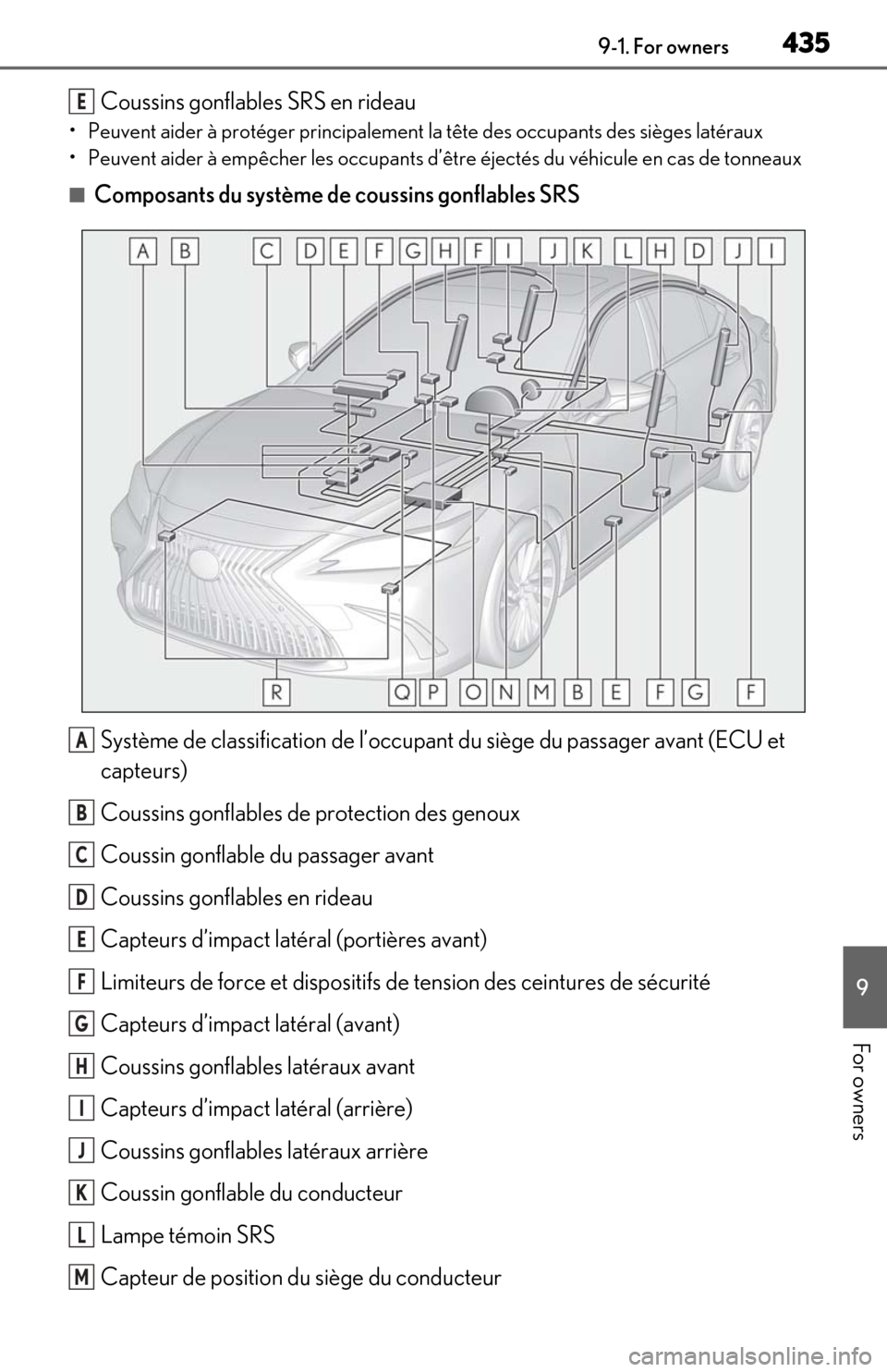
■Composants du système de coussins gonflables SRS
Système de classification de l’occupant du siège du passager avant (ECU et
capteurs)
Coussins gonflables de protection des genoux
Coussin gonflable du passager avant
Coussins gonflables en rideau
Capteurs d’impact latéral (portières avant)
Limiteurs de force et dispositifs de tension des ceintures de sécurit\
é
Capteurs d’impact latéral (avant)
Coussins gonflables latéraux avant
Capteurs d’impact latéral (arrière)
Coussins gonflables latéraux arrière
Coussin gonflable du conducteur
Lampe témoin SRS
Capteur de position du siège du conducteur
E
A
B
C
D
E
F
G
H
I
J
K
L
M
Page 438 of 462
4369-1. For owners
Contacteur de boucle de ceinture de sécurité du conducteur
Module de capteur de coussin gonflable
Voyants “AIR BAG ON” et “AIR BAG OFF”
Contacteur de boucle de ceinture de sécurité du passager avant
Capteurs d’impact avant
Votre véhicule est doté de COUSSINS GONFLABLES ÉVOLUÉS dont la con-
ception s’appuie sur les normes de sécurité des véhicules à moteur américains
(FMVSS208). Le module de capteur de coussin gonflable (ECU) contrôle le
déploiement des coussins gonflables en fonction des informations obtenues des
capteurs et d’autres éléments affichés dans le diagramme des\
composants du sys-
tème ci-dessus. Ces informations compre nnent des données relatives à la gravité
de l’accident et aux occupants. Au moment du déploiement des coussins gonfla-
bles, une réaction chimique se produit dans les gonfleurs de coussin gonflable et
les coussins gonflables se remplissent rapidement d’un gaz non toxique pour aider
à limiter le mouvement des occupants.N
O
P
Q
R
AVERTISSEMENT
■Précautions relatives aux coussins
gonflables SRS
Observez les précautions suivantes en
ce qui concerne les coussins gonflables
SRS.
Négliger de le faire pourrait occasionner
des blessures graves, voire mortelles.
●Le conducteur et tous les passagers du
véhicule doivent porter leur ceinture
de sécurité de la manière appropriée.
Les coussins gonflables SRS sont des
dispositifs supplémentaires qui doivent
être utilisés avec les ceintures de sécu-
rité.
Page 439 of 462

4379-1. For owners
9
For owners
AVERTISSEMENT
●Le coussin gonflable SRS du conduc-
teur se déploie avec une force con-
sidérable et peut occasionner des
blessures graves, voire mortelles,
notamment lorsque le conducteur se
trouve très près du coussin gonflable.
La National Highway Traffic Safety
Administration (NHTSA), aux États-
Unis, fait les recommandations
suivantes :
La zone à risque du coussin gonflable
du conducteur couvre 2 à 3 in.
(50 à 75 mm) de la zone de déploie-
ment du coussin gonflable. Pour
assurer une marge de sécurité suff-
isante, restez à 10 in. (250 mm) du
coussin gonflable. Cette distance est
mesurée depuis le centre du volant
jusqu’à votre sternum. Si maintenant
vous vous tenez assis à moins de 10 in.
(250 mm), vous pouvez changer votre
position de conduite de plusieurs
manières :
• Reculez votre siège à la position maxi-
male vous permettant d’atteindre
encore aisément les pédales.
• Inclinez légèrement le dossier du siège. Bien que les véhicules soient
conçus différemment, la plupart des
conducteurs peuvent maintenir une
distance de 10 in. (250 mm), même si
leur siège se trouve complètement
vers l’avant, simplement en inclinant un
peu le dossier du siège vers l’arrière. Si
la visibilité avant est moindre après
avoir incliné le dossier de votre siège,
utilisez un coussin ferme et non glis-
sant pour être assis plus haut ou rele-
vez le siège si cette option est
disponible sur votre véhicule.
• Si votre volant est réglable en hauteur, inclinez-le vers le bas. Cela vous per-
met d’orienter le coussin gonflable
vers votre buste plutôt que vers votre
tête et vers votre cou.
Le siège doit être réglé de la manière
recommandée ci-dessus par la NHTSA,
tout en gardant le contrôle des pédales
et du volant, ainsi que la vue sur les com-
mandes du tableau de bord.
●Si la rallonge de ceinture de sécurité a
été reliée à la boucle des ceintures de
sécurité des sièges avant sans avoir
aussi été attachée à la plaque de blo-
cage des ceintures de sécurité, les
coussins gonflables SRS avant con-
sidéreront que le conducteur et le pas-
sager avant portent tout de même leur
ceinture de sécurité même si les cein-
tures de sécurité ne sont pas
attachées. Les coussins gonflables
SRS avant peuvent alors ne pas s’acti-
ver correctement lors d’une collision,
ce qui pourrait occasionner des bless-
ures graves, voire mortelles, en cas de
collision. Assurez-vous de toujours
porter la ceinture de sécurité avec la
rallonge de ceinture de sécurité.
●Le coussin gonflable SRS du passager
avant se déploie également avec une
force considérable et peut occasion-
ner des blessures graves, voire mor-
telles, notamment lorsque le passager
avant se trouve très près du coussin
gonflable. Le siège du passager avant
doit se trouver le plus loin possible du
coussin gonflable et le dossier doit être
réglé de manière à ce que le passager
avant soit assis bien droit.