ignition Lexus GS F 2016 Owner's Manual
[x] Cancel search | Manufacturer: LEXUS, Model Year: 2016, Model line: GS F, Model: Lexus GS F 2016Pages: 628, PDF Size: 8.83 MB
Page 5 of 628
3
1
8 7
6
5
4
3
2
GS350_200t_GS F_OM_OM30E86U_(U)
9
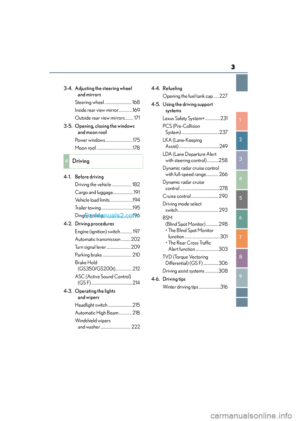
3-4. Adjusting the steering wheel and mirrors
Steering wheel ............................. 168
Inside rear view mirror...............169
Outside rear view mirrors......... 171
3-5. Opening, closing the windows and moon roof
Power windows............................. 175
Moon roof .......................................178
4-1. Before driving Driving the vehicle ..................... 182
Cargo and luggage...................... 191
Vehicle load limits ........................194
Trailer towing .................................195
Dinghy towing ...............................196
4-2. Driving procedures Engine (ignition) switch ............. 197
Automatic transmission .......... 202
Turn signal lever .......................... 209
Parking brake ............................... 210
Brake Hold (GS350/GS200t) ..................212
ASC (Active Sound Control) (GS F) ............................................214
4-3. Operating the lights and wipers
Headlight switch ..........................215
Automatic High Beam.............. 218
Windshield wipers and washer ................................ 222 4-4. Refueling
Opening the fuel tank cap ......227
4-5. Using the driving support systems
Lexus Safety System+ ................231
PCS (Pre-Collision System) ........................................237
LKA (Lane-Keeping Assist) ...........................................249
LDA (Lane Departure Alert with steering control) ............ 258
Dynamic radar cruise control with full-speed range............. 266
Dynamic radar cruise control ..........................................278
Cruise control ............................. 290
Driving mode select switch ........................................... 293
BSM (Blind Spot Monitor) ............. 298
•The Blind Spot Monitor function ..................................... 301
• The Rear Cross Traffic Alert function ........................ 303
TVD (Torque Vectoring Differential) (GS F) ................ 306
Driving assist systems ..............308
4-6. Driving tips Winter driving tips .......................316
4Driving
Page 74 of 628
721-2. Theft deterrent system
GS350_200t_GS F_OM_OM30E86U_(U)
Engine immobilizer system
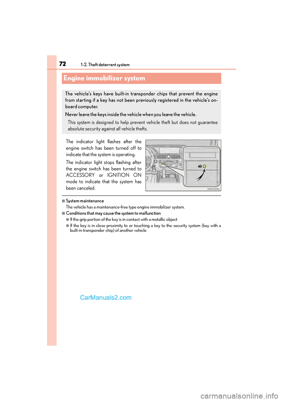
The indicator light flashes after the
engine switch has been turned off to
indicate that the system is operating.
The indicator light stops flashing after
the engine switch has been turned to
ACCESSORY or IGNITION ON
mode to indicate that the system has
been canceled.
■System maintenance
The vehicle has a maintenance-free type engine immobilizer system.
■Conditions that may cause the system to malfunction
●If the grip portion of the key is in contact with a metallic object
●If the key is in close proximity to or touching a key to the security system (key with a
built-in transponder chip) of another vehicle
The vehicle’s keys have built-in transponder chips that prevent the engine
from starting if a key has not been previously registered in the vehicle’s on-
board computer.
Never leave the keys inside the vehicle when you leave the vehicle.
This system is designed to help prevent vehicle theft but does not guarantee
absolute security against all vehicle thefts.
Page 76 of 628
741-2. Theft deterrent system
GS350_200t_GS F_OM_OM30E86U_(U)
Alarm
The alarm uses light and sound to give an alert when an intrusion is detected.
The alarm is triggered in the following situations when the alarm is set:
●A locked door or trunk is unlocked or opened in any way other than using the
entry function, wireless remote control or mechanical key. (The doors will lock
again automatically.)
●The hood is opened.
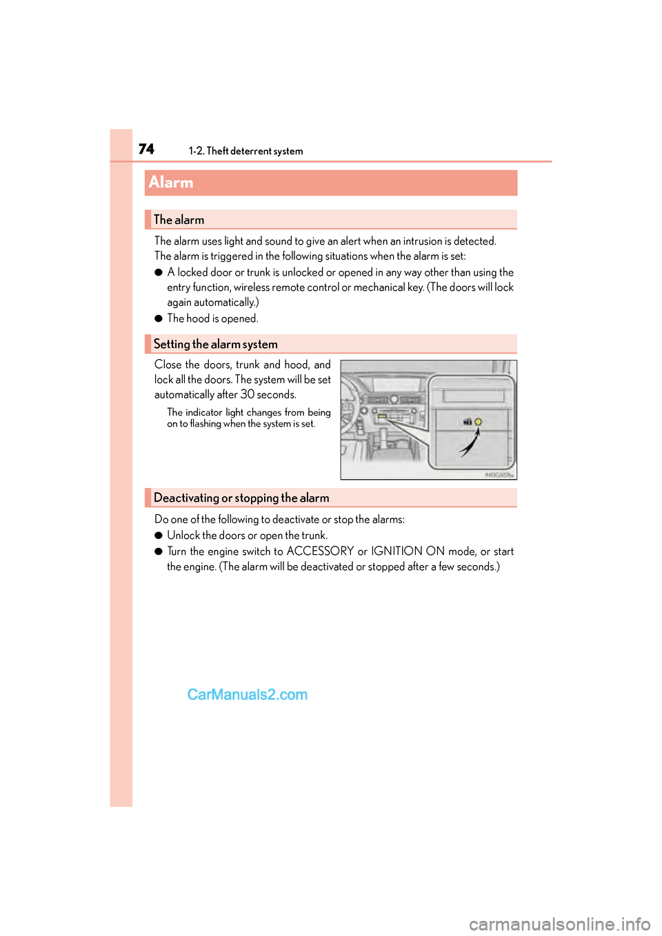
Close the doors, trunk and hood, and
lock all the doors. The system will be set
automatically after 30 seconds.
The indicator light changes from being
on to flashing when the system is set.
Do one of the following to deactivate or stop the alarms:
●Unlock the doors or open the trunk.
●Turn the engine switch to ACCESSORY or IGNITION ON mode, or start
the engine. (The alarm will be deactivated or stopped after a few seconds.)
The alarm
Setting the alarm system
Deactivating or stopping the alarm
Page 83 of 628
GS350_200t_GS F_OM_OM30E86U_(U)
812. Instrument cluster
2
Instrument cluster
*1: These lights turn on when the engine switch is turned to IGNITION ON mode toindicate that a system check is being performed. They will turn off after the engine is
started, or after a few seconds. There may be a malfunction in a system if a light does
not come on, or turn off. Have the vehicle inspected by your Lexus dealer.
*2: On some models
*3: The light flashes to indicate a malfunction.
*4: GS350/GS200t
*5:GS F
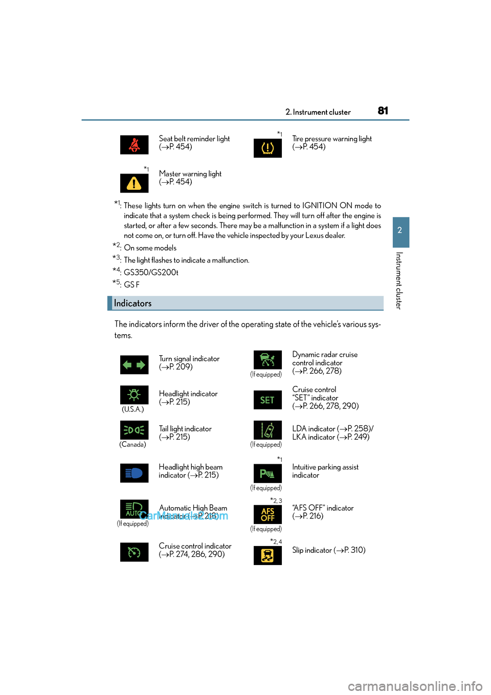
The indicators inform the driver of the operating state of the vehicle’s various sys-
tems.
Seat belt reminder light
( → P. 4 5 4 )*1Tire pressure warning light
(→ P. 4 5 4 )
*1Master warning light
(→ P. 4 5 4 )
Indicators
Turn signal indicator
(→ P. 2 0 9 )
(If equipped)
Dynamic radar cruise
control indicator
(→ P. 2 6 6 , 2 7 8 )
(U.S.A.)
Headlight indicator
(→ P. 2 1 5 ) Cruise control
“SET” indicator
(
→ P. 266, 278, 290)
(Canada)
Tail light indicator
(→ P. 2 1 5 )
(If equipped)
LDA indicator ( →P. 2 5 8 ) /
LKA indicator ( →P. 2 4 9 )
Headlight high beam
indicator ( →P. 2 1 5 )
*1
(If equipped)
Intuitive parking assist
indicator
(If equipped)
Automatic High Beam
indicator ( →P. 2 1 8 )*2, 3
(If equipped)
“AFS OFF” indicator
(→ P. 2 1 6 )
Cruise control indicator
( → P. 274, 286, 290)
*2, 4
Slip indicator ( →P. 3 1 0 )
Page 86 of 628
84
GS350_200t_GS F_OM_OM30E86U_(U)2. Instrument cluster
*1: Refer to the “NAVIGATION AND MULTIMEDIA SYSTEM OWNER’S MANUAL”.
*2: These lights turn on when the engine switch is turned to IGNITION ON mode to
indicate that a system check is being performed. They will turn off after the engine is
started, or after a few seconds. There may be a malfunction in a system if a light does
not come on, or turn off. Have the vehicle inspected by your Lexus dealer.
*3: GS350/GS200t
*4: The light flashes to indicate that the system is operating.
*5:GS F
*6: The light turns on when the system is turned off.
*7: In order to confirm operation, the BSM outside rear view mirror indicators illuminate in the following situations:
• When the engine switch is in IGNITION ON mode, the BSM function is enabled
on of the multi-information display
• When the BSM function is enabled on of the multi-information display, the
engine switch is turned to IGNITION ON mode.
If the system is functioning correctly, the BSM outside rear view mirror indicators will
turn off after a few seconds.
If the BSM outside rear view mirror indicators do not illuminate or do not turn off,
there may be a malfunction in the system.
If this occurs, have the vehicle inspected by your Lexus dealer.
*8: This light illuminates on the outside rear view mirrors.
*9: This light illuminates on the center panel.
*10: When the outside temperature is approximately 37 °F (3 °C) or lower, the indicator
will flash for approximately 10 seconds, then stay on.
Page 91 of 628
GS350_200t_GS F_OM_OM30E86U_(U)
892. Instrument cluster
2
Instrument cluster
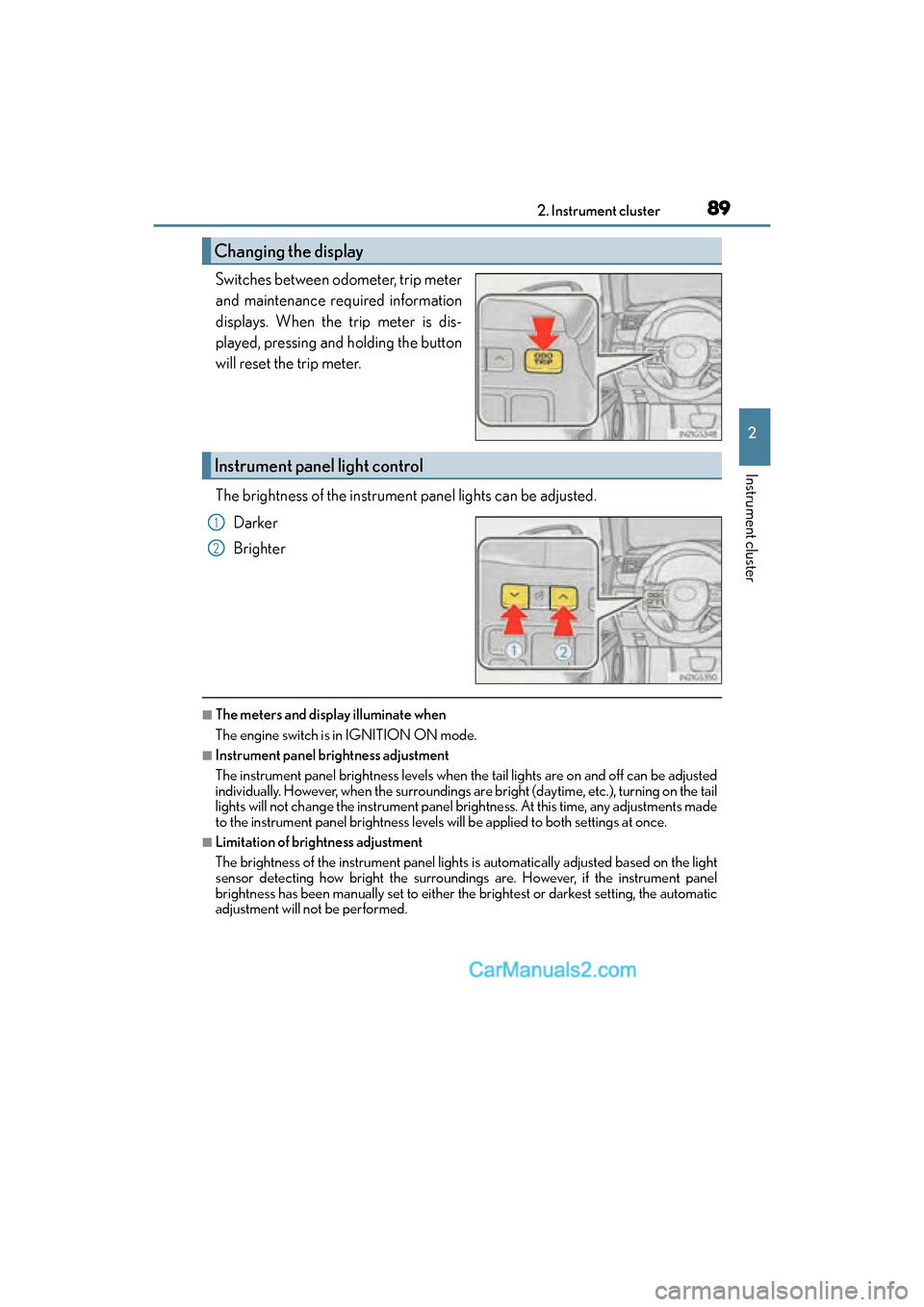
Switches between odometer, trip meter
and maintenance required information
displays. When the trip meter is dis-
played, pressing and holding the button
will reset the trip meter.
The brightness of the instrument panel lights can be adjusted.Darker
Brighter
■The meters and display illuminate when
The engine switch is in IGNITION ON mode.
■Instrument panel brightness adjustment
The instrument panel brightness levels when the tail lights are on and off can be adjusted
individually. However, when the surroundings ar e bright (daytime, etc.), turning on the tail
lights will not change the instrument panel brightness. At this time, any adjustments made
to the instrument panel brightness levels w ill be applied to both settings at once.
■Limitation of brightness adjustment
The brightness of the instrument panel lights is automatically adjusted based on the light
sensor detecting how bright the surroundings are. However, if the instrument panel
brightness has been manually set to either the brightest or darkest setting, the automatic
adjustment will not be performed.
Changing the display
Instrument panel light control
1
2
Page 99 of 628
GS350_200t_GS F_OM_OM30E86U_(U)
972. Instrument cluster
2
Instrument cluster
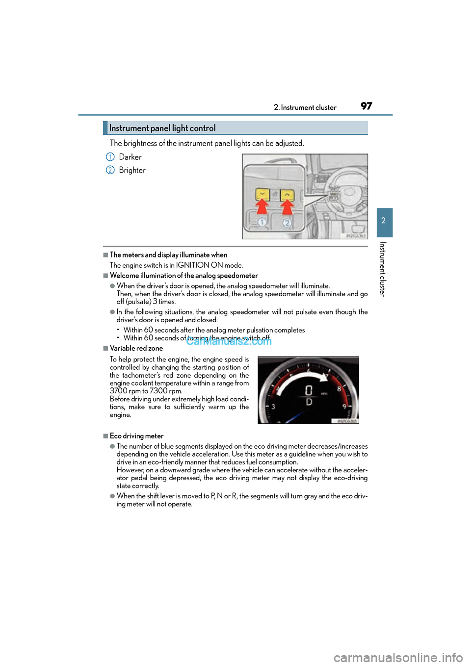
The brightness of the instrument panel lights can be adjusted.Darker
Brighter
■The meters and display illuminate when
The engine switch is in IGNITION ON mode.
■Welcome illumination of the analog speedometer
●When the driver’s door is opened, the analog speedometer will illuminate.
Then, when the driver’s door is closed, the analog speedometer will illuminate and go
off (pulsate) 3 times.
●In the following situations, the analog sp eedometer will not pulsate even though the
driver’s door is opened and closed:
• Within 60 seconds after the analog meter pulsation completes
• Within 60 seconds of turning the engine switch off
■Va r i a b l e r e d z o n e
■Eco driving meter
●The number of blue segments displayed on the eco driving meter decreases/increases
depending on the vehicle acceleration. Use th is meter as a guideline when you wish to
drive in an eco-friendly manner that reduces fuel consumption.
However, on a downward grade where the vehicle can accelerate without the acceler-
ator pedal being depressed, the eco driving meter may not display the eco-driving
state correctly.
●When the shift lever is moved to P, N or R, the segments will turn gray and the eco driv-
ing meter will not operate.
Instrument panel light control
1
2
To help protect the engine, the engine speed is
controlled by changing the starting position of
the tachometer’s red zone depending on the
engine coolant temperature within a range from
3700 rpm to 7300 rpm.
Before driving under extremely high load condi-
tions, make sure to sufficiently warm up the
engine.
Page 108 of 628
106
GS350_200t_GS F_OM_OM30E86U_(U)2. Instrument cluster
■G-force display
●The G-force values may not be zero even when the vehicle is parked, such as when it is
parked on an incline.
●Depending on the vehicle usage conditions, the brake fluid pressure display may not
reach its maximum reading even though the brake pedal is fully depressed.
●If a battery terminal is disconnected and reconnected, the steering amount display may
be disabled temporarily. After driving the vehi
cle for a while, the display will be enabled.
■System check display
After turning the engine switch to IGNITION ON mode, opening image is displayed
while system operation is checked. When the system check is complete, the normal
screen will return.
■Suspension of the settings display
In the following situations, the settings display using the meter control switches will be
suspended.
●When a warning message appears on the multi-information display
●When the vehicle begins to move
■Tire inflation pressure
●It may take a few minutes to display the tire inflation pressure after the engine switch is
turned to IGNITION ON mode. It may also take a few minutes to display the tire infla-
tion pressure after inflation pressure has been adjusted.
●“---” may be displayed if the tire information cannot be determined due to unfavorable
radio wave conditions.
●Tire inflation pressure changes with temperature. The displayed values may also be dif-
ferent from the values measured using a tire pressure gauge.
■When disconnecting and reconnecting battery terminals
The drive information will be reset.
■Liquid crystal display
→P. 9 0
WA R N I N G
■Caution for use while driving
●When operating the mult i-information display while drivin g, pay extra attention to the
safety of the area around the vehicle.
●Do not look continuously at the multi-information display while driving as you may fail
to see pedestrians, objects on the road, etc. ahead of the vehicle.
■Cautions during setting up the display
As the engine needs to be operating during setting up the display, ensure that the vehi-
cle is parked in a place with adequate ventilation. In a closed area such as a garage,
exhaust gases including harmful carbon monoxide (CO) may collect and enter the
vehicle. This may lead to death or a serious health hazard.
Page 120 of 628
118
GS350_200t_GS F_OM_OM30E86U_(U)2. Instrument cluster
■Start-up display
When the engine is started, the name of the vehicle is displayed on the multi-information
display.
While the start-up display is being displayed, the meter display cannot be changed even
if the drive mode is changed.
When the start-up display is finished, the meter display for
the currently selected mode will be displayed.
■Torque distribution display
Torque distribution may not be displayed correctly in some cases, such as when the vehi-
cle passes over road expansion joints.
■G-force display
●The G-force values may not be zero even when the vehicle is parked, such as when it is
parked on an incline.
●The steering amount, accelerator pedal input, and brake fluid pressure displays are dis-
abled until the engine has warmed up (the variable red zone of the tachometer has
retracted to 7300 rpm).
After the engine has warmed up, these displays will be enabled.
●Depending on the vehicle usage conditions, the brake fluid pressure display may not
reach its maximum reading even though the brake pedal is fully depressed.
●If a battery terminal is disconnected and reconnected, the steering amount display may
be disabled temporarily. After driving the vehi cle for a while, the display will be enabled.
■Suspension of the settings display
In the following situations, operation of the settings display will be temporarily sus-
pended.
●When a warning message appears on the multi-information display
●When the vehicle begins to move
■Tire inflation pressure
●It may take a few minutes to display the tire inflation pressure after the engine switch is
turned to IGNITION ON mode. It may also take a few minutes to display the tire infla-
tion pressure after inflation pressure has been adjusted.
●“---” may be displayed if the tire position information cannot be determined due to
unfavorable radio wave conditions.
●Tire inflation pressure changes with temperature. The displayed values may also be dif-
ferent from the values measured using a tire pressure gauge.
■When disconnecting and reconnecting battery terminals
The following information data will be reset:
●Lap timer: Measured lap times, history
●G-force: Record of the maximum G-forces
■Using the lap timer
If the engine is stopped while a lap is being timed, the lap timer will stop and the lap time
up to that point will be recorded.
■Liquid crystal display
→ P. 9 8
Page 128 of 628

126
GS350_200t_GS F_OM_OM30E86U_(U)2. Instrument cluster
■Head-up display
●The head-up display may seem dark and hard to see when viewed through sunglasses,
especially polarized sunglasses.
Adjust the brightness of the head-up
display or remove your sunglasses.
●When the head-up display is turned off, it will remain off even if the engine switch is
turned to IGNITION ON mode after the engine switch has been turned off.
●The startup image will be displayed on the head-up display after the engine switch has
been turned to IGNITION ON mode while the head-up display switch is set to on.
■Head-up rev indicator
●The head-up display is linked to the rev indicator in the meter.
●Whether or not to display the rev indicator in the head-up display, as well as display tim-
ing, can be changed through the settings for the rev indicator in the meter. ( →P. 1 1 7 )
■When the battery is disconnected
The customize settings of the head-up display will be reset.
■Head-up display automatic position adjustment
If the display position is recorded into me mory, the head-up display will be automatically
adjusted to the desired position. ( →P. 1 6 0 )
WA R N I N G
■Before using the head-up display
Check that the position and brightness of the head-up display image does not interfere
with safe driving. Incorrect adjustment of the image’s position or brightness may
obstruct the driver’s view and lead to an accident, resulting in death or serious injury.
NOTICE
■To prevent damage to components
●Do not touch the inside of the head-up display projector or thrust sharp edges or the
like into the projector.
Doing so could cause mechanical malfunctions.
●Do not place any drinks near the head-up dis-
play projector. If the projector gets wet, elec-
trical malfunctions may result.
●Do not place anything on or put stickers onto
the head-up display projector.
Doing so could interrupt head-up display
indications.