instrument cluster Lexus IS250C 2012 Instrument cluster / LEXUS 2012 IS250C,IS350C OWNERS MANUAL (OM53A62U)
[x] Cancel search | Manufacturer: LEXUS, Model Year: 2012, Model line: IS250C, Model: Lexus IS250C 2012Pages: 632, PDF Size: 6.77 MB
Page 3 of 632

1
2
3
4
5
6
7
3
2-1. Driving proceduresDriving the vehicle ........................ 138
Engine (ignition) switch .............. 148
Automatic transmission.............. 153
Manual transmission .................... 160
Turn signal lever ............................ 162
Parking brake ................................. 163
Horn.................................................... 165
2-2. Instrument cluster Gauges and meters ..................... 166
Indicators and warning lights.................................................. 172
Multi-information display........... 176
2-3. Operating the lights and windshield wipers
Headlight switch ............................. 181
Fog light switch .............................. 185
Windshield wipers and washer............................................. 187
Headlight cleaner switch ........... 194 2-4. Using other driving systems
Cruise control ................................ 195
Dynamic radar cruise control............................................. 199
Intuitive parking assist ................. 213
Driving assist systems.................. 219
Hill-start assist control ............... 225
PCS (Pre-Collision System).... 227
2-5. Driving information Cargo and luggage ..................... 234
Vehicle load limits ........................ 237
Winter driving tips ....................... 238
Trailer towing ................................. 242
Dinghy towing (vehicles with an automatic
transmission) ............................... 243
Dinghy towing (vehicles with a manual
transmission) ............................... 244
2When driving
Page 137 of 632

When driving2
137
2-1. Driving proceduresDriving the vehicle.................. 138
Engine (ignition) switch ......... 148
Automatic transmission ........ 153
Manual transmission .............. 160
Turn signal lever ....................... 162
Parking brake ........................... 163
Horn ............................................ 165
2-2. Instrument cluster Gauges and meters ................ 166
Indicators and warning lights ......................................... 172
Multi-information display ...... 176
2-3. Operating the lights and windshield wipers
Headlight switch....................... 181
Fog light switch ........................ 185
Windshield wipers and washer ..................................... 187
Headlight cleaner switch...... 194 2-4. Using other driving
systems
Cruise control.......................... 195
Dynamic radar cruise control ..................................... 199
Intuitive parking assist ........... 213
Driving assist systems ............ 219
Hill-start assist control ......... 225
PCS (Pre-Collision System) .................................. 227
2-5. Driving information Cargo and luggage ............... 234
Vehicle load limits .................. 237
Winter driving tips ................. 238
Trailer towing .......................... 242
Dinghy towing (vehicles with an
automatic transmission).... 243
Dinghy towing (vehicles with a manual
transmission) ........................ 244
Page 166 of 632

166
2-2. Instrument cluster
Gauges and meters
The units used on the speedometer and the tachometer gauge display may
differ depending on the model/type.
The following gauges, meters and display illuminate when the
“ENGINE START STOP” switch is in IGNITION ON mode.
Speedometer
Displays the vehicle speed.
Multi-information display
P. 1 76
Tachometer
Displays the engine speed in revolutions per minute.
Tacho indicator
When the set engine speed is reached, this ring-shaped indicators comes
on in yellow. The indicator comes on in red when the engine speed
reaches a dangerous range.
Engine coolant temperature gauge
Displays the engine coolant temperature.
Page 167 of 632

167
2-2. Instrument cluster
2
When driving
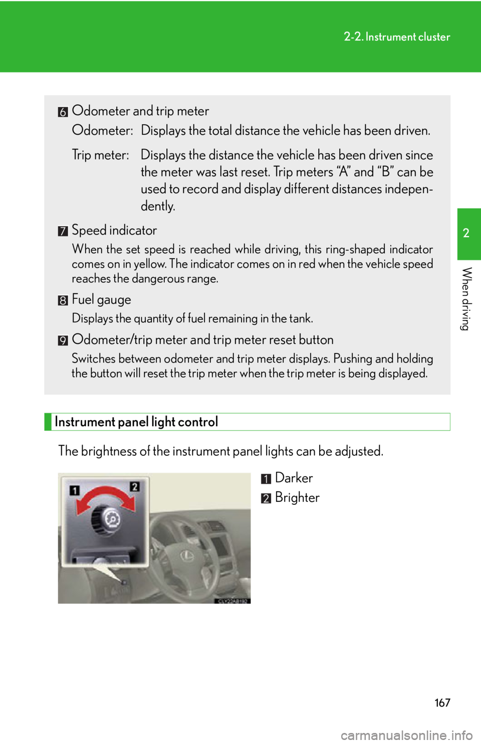
Instrument panel light controlThe brightness of the instrument panel lights can be adjusted. Darker
Brighter
Odometer and trip meter
Odometer: Displays the total distance the vehicle has been driven.
Trip meter: Displays the distance the vehicle has been driven since
the meter was last reset. Trip meters “A” and “B” can be
used to record and display different distances indepen-
dently.
Speed indicator
When the set speed is reached while driving, this ring-shaped indicator
comes on in yellow. The indicator comes on in red when the vehicle speed
reaches the dangerous range.
Fuel gauge
Displays the quantity of fuel remaining in the tank.
Odometer/trip meter and trip meter reset button
Switches between odometer and trip meter displays. Pushing and holding
the button will reset the trip meter when the trip meter is being displayed.
Page 168 of 632

168
2-2. Instrument cluster
Speed and tacho indicators■ Turning the indicator on/off
Bring up the satellite switch mode
on the multi-information display.
Press “”, “” or the “ON/OFF”
button.
Select the item whose setting is to
be changed.
Press “” or “” to display the item
whose setting is to be changed.
Change the settings.
Press “ON/OFF” button to change
the settings.
STEP1
STEP2
STEP3
Page 169 of 632

169
2-2. Instrument cluster
2
When driving
■Changing the indicator setting
The satellite switch can be used to change the set speed at which the
yellow speed or tacho ind icator ring comes on.
The setting can be made only when the “ENGINE START STOP”
switch is in IGNITION ON mode and the vehicle is stopped.
Push “
” or “” to select the speed or tach o indicator set mode. ( ) Turn
the speed or tacho indi cator to “OFF” and then “ON” by pushing the
“ON/OFF” button. ( )
After one second, the mode enters
the indicator setting mode.
The speedometer or tachometer
needle moves to the previously set
speed.
STEP1
Page 170 of 632

170
2-2. Instrument cluster
Push “” or “” within 6 seconds of the speedometer or tachometer nee-
dle moving to change the setting of the desired speed, then turn the indi-
cator mode to “ON” by pushing the “ON/OFF” button.
Pushing and holding the button chan ges values at a faster rate.
If the satellite switch is not operated for some time, the multi-information dis-
play returns to its previously displayed content.
The yellow indicator is displayed to indicate that the desired speed has
been set.
STEP2
Page 171 of 632

171
2-2. Instrument cluster
2
When driving
■Speed indicator display conditions and vehicle speed setting range
Vehicle speed setting range: Approximately 30 to 100 mph (approximately 50 to 160 km/h)
When the maximum speed is selected, the speed indicator comes on only in red.
■Tacho indicator display conditions and engine speed setting range
Engine rpm setting range: Approximately 2000 to 6500 rpm (r/min)
When the maximum rpm is selected, the tacho indicator comes on only in red.
■The brightness of the instrument panel lights
When the headlight switch is turned to on, the brightness will be reduced slightly
unless the control dial is turned fully clockwise.
NOTICE
■To prevent damage to the engine and its components
●Do not let the indicator needle of the tachometer enter the red zone, which indi-
cates the maximum engine speed.
●The engine may be overheating if the temperature gauge is in the red zone (H). In
this case, immediately stop the vehicle in a safe place, and check the engine after
it has cooled completely. ( P. 5 4 2 )
Page 172 of 632

172
2-2. Instrument cluster
Indicators and warning lights
The indicator and warning lights on the instrument cluster and center
panel inform the driver of the status of the vehicle’s various systems.
Instrument cluster
The units used on the speedometer and the tachometer gauge display may
differ depending on the model/type.
Center panel
Page 173 of 632

173
2-2. Instrument cluster
2
When driving
■Indicators
The indicators inform the driver of th e operating state of the vehi-
cle’s various systems.
Turn signal indicator
( P. 1 6 2 )
(vehicles with
an automatic
transmission)
“ECT SNOW” indicator
( P. 1 5 4 )
Headlight high beam indi-
cator ( P. 1 8 3 )
(vehicles with
a manual
transmission)
“ETCS SNOW” indicator
( P. 161)
(U.S.A.)
Headlight indicator
( P. 181)
(vehicles with
an automatic
transmission)
“ECT PWR” indicator
( P. 1 5 4 )
(Canada)
Tail light indicator
( P. 181) Cruise control indicator
( P. 195, 199)
Front fog light indicator
( P. 1 8 5 )
(if equipped)
Intuitive parking assist
indicator ( P. 2 1 3 )
(vehicles with an automatic trans-
mission)
Shift position and shift range indica-
tors ( P. 1 5 3 )
Slip indicator ( P. 220)
VSC off indicator
( P. 2 2 1 )
SRS airbag on-off indica-
tor ( P. 1 1 9 )
*1, 2
*1
*1