warning LEXUS IS350 2022 Owner's Guide
[x] Cancel search | Manufacturer: LEXUS, Model Year: 2022, Model line: IS350, Model: LEXUS IS350 2022Pages: 440, PDF Size: 22.72 MB
Page 53 of 440
511-2. Child safety
1
For safety and security
ufacturer’s operation manual
regarding the installation, using the
top tether strap to latch onto the
top tether strap anchor. (P.51)
6 After installing the child restraint
system, rock it back and forth to
ensure that it is installed securely.
( P.48)
■Laws and regulations pertaining to
anchors
The LATCH system conforms to
FMVSS225 or CMVSS210.2.
Child restraint systems conforming to
FMVSS213 or CMVSS213 specifications
can be used.
This vehicle is designed to conform to SAE
J1819.
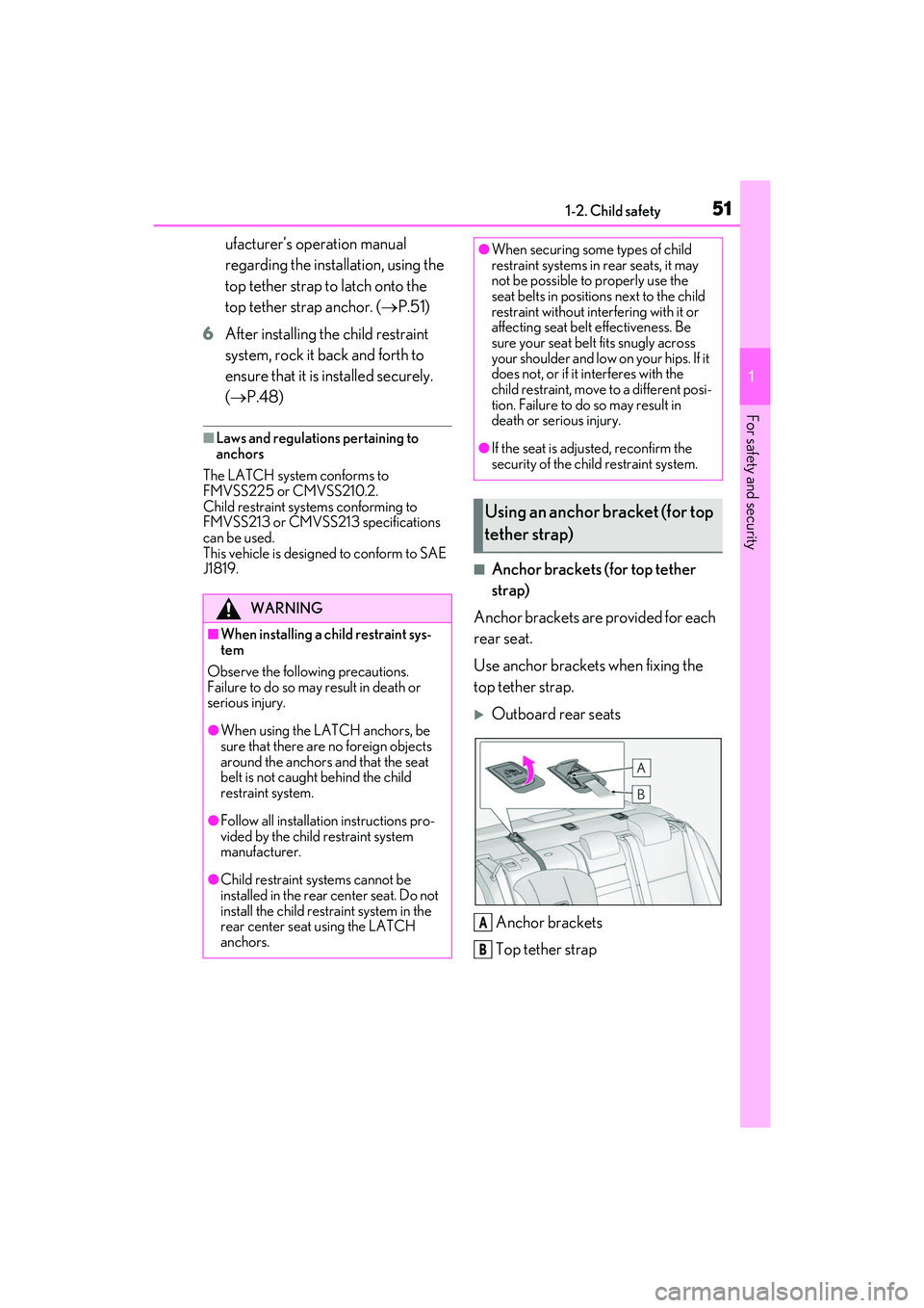
■Anchor brackets (for top tether
strap)
Anchor brackets are provided for each
rear seat.
Use anchor brackets when fixing the
top tether strap.
Outboard rear seats
Anchor brackets
Top tether strap
WARNING
■When installing a child restraint sys-
tem
Observe the following precautions.
Failure to do so may result in death or
serious injury.
●When using the LATCH anchors, be
sure that there are no foreign objects
around the anchors and that the seat
belt is not caught behind the child
restraint system.
●Follow all installation instructions pro-
vided by the child restraint system
manufacturer.
●Child restraint systems cannot be
installed in the rear center seat. Do not
install the child restraint system in the
rear center seat using the LATCH
anchors.
●When securing some types of child
restraint systems in rear seats, it may
not be possible to properly use the
seat belts in position s next to the child
restraint without interfering with it or
affecting seat belt effectiveness. Be
sure your seat belt fits snugly across
your shoulder and low on your hips. If it
does not, or if it interferes with the
child restraint, move to a different posi-
tion. Failure to do so may result in
death or serious injury.
●If the seat is adjusted, reconfirm the
security of the child restraint system.
Using an anchor bracket (for top
tether strap)
A
B
Page 54 of 440
521-2. Child safety
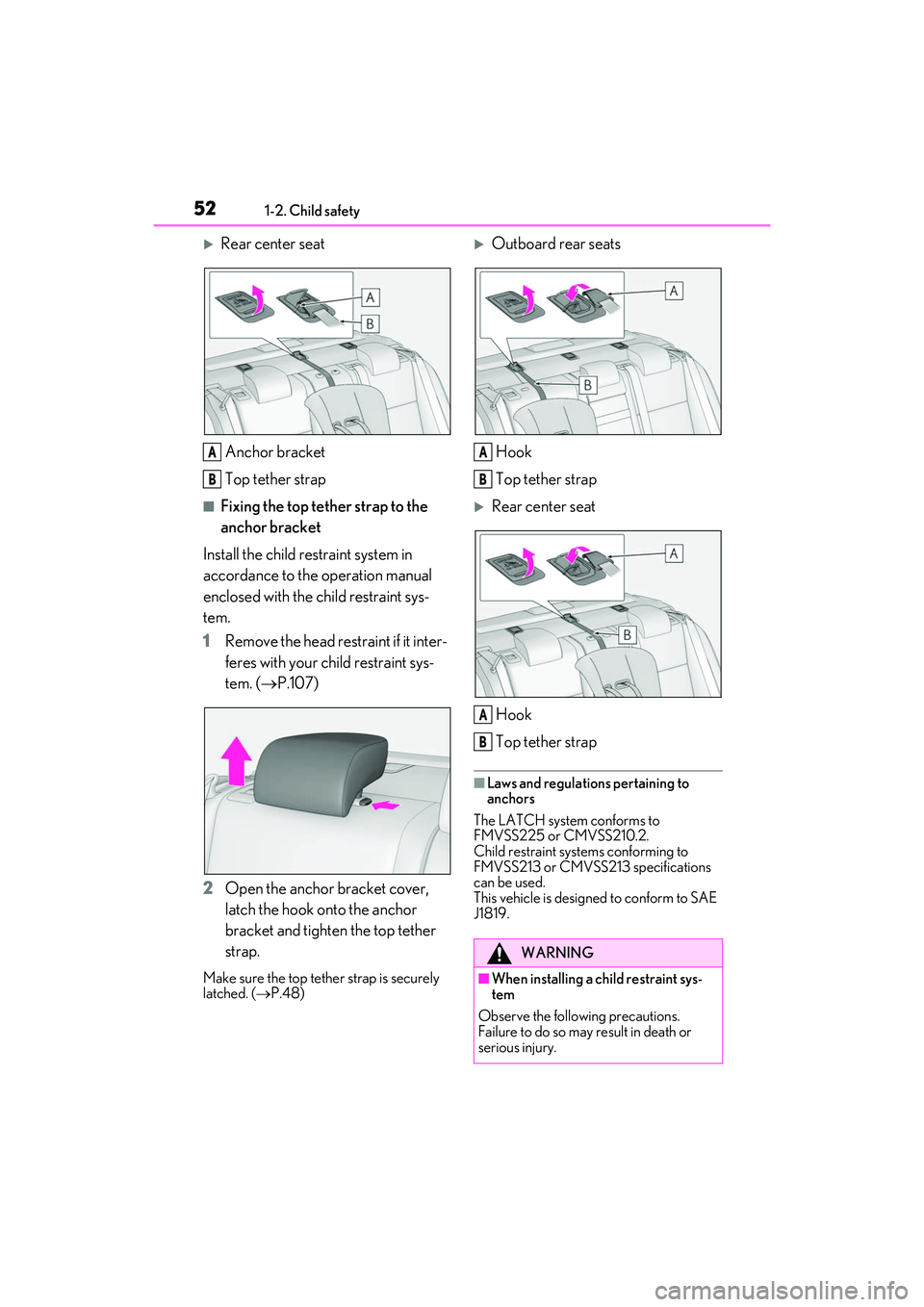
Rear center seatAnchor bracket
Top tether strap
■Fixing the top tether strap to the
anchor bracket
Install the child restraint system in
accordance to the operation manual
enclosed with the child restraint sys-
tem.
1 Remove the head restraint if it inter-
feres with your child restraint sys-
tem. ( P.107)
2 Open the anchor bracket cover,
latch the hook onto the anchor
bracket and tighten the top tether
strap.
Make sure the top tether strap is securely
latched. ( P.48)
Outboard rear seats
Hook
Top tether strap
Rear center seat
Hook
Top tether strap
■Laws and regulations pertaining to
anchors
The LATCH system conforms to
FMVSS225 or CMVSS210.2.
Child restraint systems conforming to
FMVSS213 or CMVSS213 specifications
can be used.
This vehicle is designed to conform to SAE
J1819.
A
B
WARNING
■When installing a child restraint sys-
tem
Observe the following precautions.
Failure to do so may result in death or
serious injury.
A
B
A
B
Page 55 of 440
531-2. Child safety
1
For safety and security
WARNING
●Firmly attach the top tether strap and
make sure that the belt is not twisted.
●Do not attach the top tether strap to
anything other than the anchor
bracket.
●Follow all installation instructions pro-
vided by the child restraint system
manufacturer.
●When installing the child restraint sys-
tem with the head restraint being
raised, after the head restraint has
been raised and then the anchor
bracket has been fixed, do not lower
the head restraint.
●If the seat is adju sted, reconfirm the
security of the child restraint system.
NOTICE
■Anchor brackets (for top tether
strap)
When not in use, make certain to close
the lid. If it remains open, the lid may be
damaged.
Page 65 of 440

63
2
2
Vehicle status information and indicators
Vehicle status informationand indicators
.2-1. Instrument cluster
Warning lights and indicators........................................................... 64
Gauges and meters .................... 69
Multi-information display.......... 75
Fuel consumption information ........................................................... 82
Page 66 of 440

642-1. Instrument cluster
2-1.Instrument cluster
For the purpose of explanation, the following illustrations display all warning lights
and indicators illuminated.
Except F SPORT models
F SPORT models
The location of warning lights and indicators may differ depending on the selected main
meter location.
Warning lights and indicators
The warning lights and indicators on th e instrument cluster, center panel and
outside rear view mirrors inform the driver of the status of the vehicle’s various
systems.
Warning lights and indicators displayed on the instrument cluster
Page 67 of 440
652-1. Instrument cluster
2
Vehicle status information and indicators
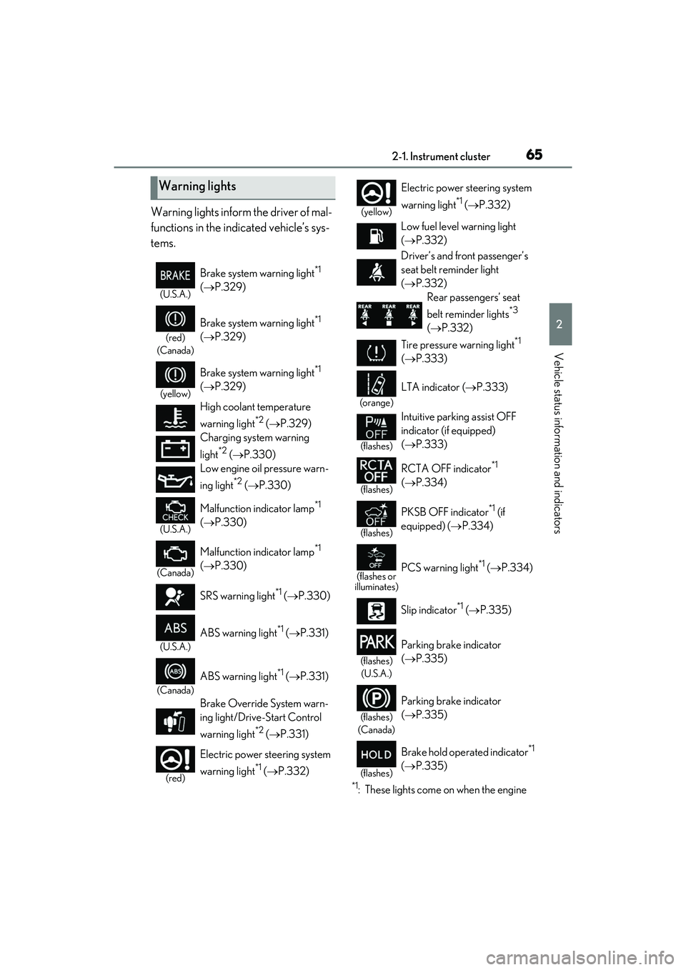
Warning lights inform the driver of mal-
functions in the indicated vehicle’s sys-
tems.
*1: These lights come on when the engine
Warning lights
(U.S.A.)
Brake system warning light*1
( P.329)
(red)
(Canada)
Brake system warning light*1
( P.329)
(yellow)
Brake system warning light*1
( P.329)
High coolant temperature
warning light
*2 ( P.329)
Charging system warning
light
*2 ( P.330)
Low engine oil pressure warn-
ing light
*2 ( P.330)
(U.S.A.)
Malfunction indicator lamp*1
( P.330)
(Canada)
Malfunction indicator lamp*1
( P.330)
SRS warning light
*1 ( P.330)
(U.S.A.)
ABS warning light*1 (P.331)
(Canada)
ABS warning light*1 (P.331)
Brake Override System warn-
ing light/Drive-Start Control
warning light
*2 ( P.331)
(red)
Electric power steering system
warning light
*1 ( P.332)
(yellow)
Electric power st eering system
warning light
*1 ( P.332)
Low fuel level warning light
( P.332)
Driver’s and front passenger’s
seat belt re minder light
( P.332)
Rear passengers’ seat
belt reminder lights
*3
( P.332)
Tire pressure warning light
*1
( P.333)
(orange)
LTA indicator ( P.333)
(flashes)
Intuitive parking assist OFF
indicator (if equipped)
( P.333)
(flashes)
RCTA OFF indicator*1
( P.334)
(flashes)
PKSB OFF indicator*1 (if
equipped) ( P.334)
(flashes or
illuminates)PCS warning light*1 ( P.334)
Slip indicator
*1 ( P.335)
(flashes)
(U.S.A.)
Parking brake indicator
( P.335)
(flashes)
(Canada)
Parking brake indicator
( P.335)
(flashes)
Brake hold operated indicator*1
( P.335)
Page 68 of 440

662-1. Instrument cluster
switch is turned to IGNITION ON
mode to indicate that a system check is
being performed. They will turn off after
the engine is started, or after a few sec-
onds. There may be a malfunction in a
system if the lights do not come on, or
turn off. Have the vehicle inspected by
your Lexus dealer.
*2: This light illuminates on the multi-infor- mation display.
*3: This light illuminates on the center panel.
The indicators inform the driver of the
operating state of the vehicle’s various
systems.
WARNING
■If a safety system warning light does
not come on
Should a safety system light such as the
ABS and SRS warning light not come on
when you start the engine, this could
mean that these systems are not available
to help protect you in an accident, which
could result in death or serious injury.
Have the vehicle inspected by your
Lexus dealer immediately if this occurs.
Indicators
Turn signal indicator ( P.138)
(U.S.A.)
Headlight indicator (P.145)
(Canada)
Tail light indicator ( P.145)
Headlight high beam indicator
( P.146)
Automatic High Beam indicator
( P.147)
PCS warning light*1, 2 ( P.168)
Cruise control indicator
( P.194)
Dynamic radar cruise control
indicator ( P.187)
Cruise control “SET” indicator
( P.187)
(white)
LTA indicator ( P.180)
(green)
LTA indicator ( P.165, 180)
(orange)
(flashes)LTA indicator ( P.180)
BSM outside rear view mirror
indicators
*3, 4 ( P.197, 210)
BSM OFF indicator
*1, 2
( P.197)
Intuitive parking assist OFF
indicator
*2(if equipped)
( P.204)
RCTA OFF indicator
*1, 2
( P.210)
PKSB OFF indicator
*1, 2 (if
equipped) ( P.217)
(flashes)
Slip indicator*1 ( P.230)
VSC OFF indicator
*1, 2
( P.230)
Smart access system with
push-button start indicator
*5
( P.130)
(U.S.A.)
Parking brake indicator
( P.139)
Page 71 of 440

692-1. Instrument cluster
2
Vehicle status information and indicators
■Locations of gauges and meters (except F SPORT models)
The units of measure may differ depending on the intended destination of the vehicle.
Engine coolant temperature gauge
Displays the engine coolant temperature
Tachometer
Displays the engine speed in revolutions per minute
Outside temperature
Displays the outside temperature within the range of -40°F (-40°C) to 122°F (50°C)
Multi-information display
Presents the driver with a variety of vehicle data ( P.75)
Displays warning messages if a malfunction occurs (P.338)
Clock
Time displayed is linked to the anal og clock on the center panel. (P.260)
Speedometer
Fuel gauge
Displays the quantity of fuel remaining in the tank
Shift position and gear position ( P.134)
Odometer and trip meter display ( P.74)
Gauges and meters
Meter display
A
B
C
D
E
F
G
H
I
Page 72 of 440

702-1. Instrument cluster
■Locations of gauges and meters (F SPORT models)
Main meter in center position (IS350 AWD/IS350/IS300 AWD/IS300)
The units of measure may differ depending on the intended destination of the vehicle.
Engine coolant temperature gauge
Displays the engine coolant temperature
Outside temperature
Displays the outside temperature within t he range of -40°F (-40°C) to 122°F (50°C)
Tachometer
Displays the engine speed in revolutions per minute
When sport mode is selected for the driving mode, the periphery of the tachometer will
change color and the scale of the tachometer will be emphasized.
Speedometer
Shift position and gear position ( P.134)
Multi-information display
Presents the driver with a variety of vehicle data ( P.75)
Displays warning messages if a malfunction occurs (P.338)
Clock
Time displayed is linked to the anal og clock on the center panel. (P.260)
Fuel gauge
Displays the quantity of fuel remaining in the tank
Odometer and trip meter display ( P.74)
A
B
C
D
E
F
G
H
I
Page 73 of 440
712-1. Instrument cluster
2
Vehicle status information and indicators
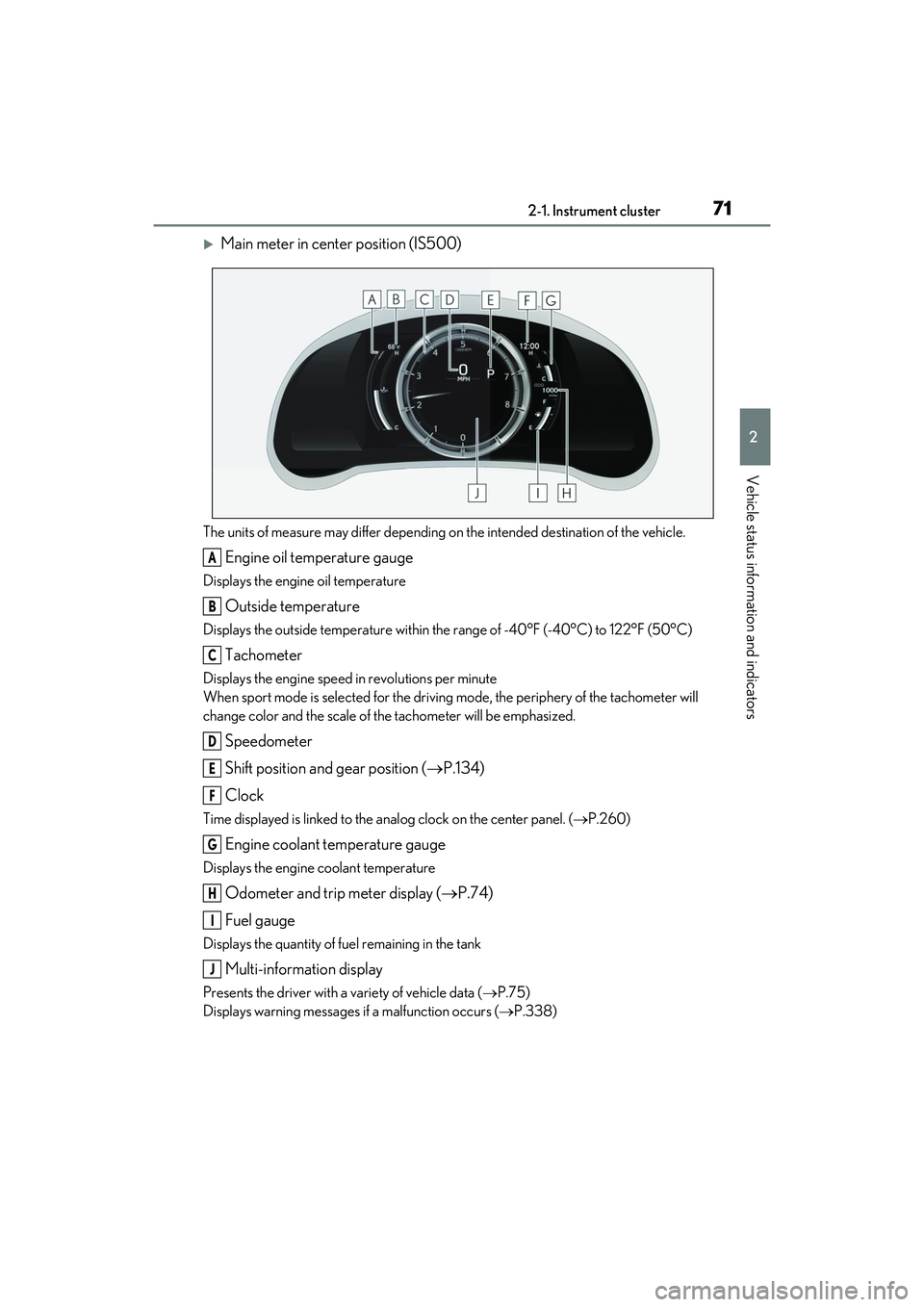
Main meter in center position (IS500)
The units of measure may differ depending on the intended destination of the vehicle.
Engine oil temperature gauge
Displays the engine oil temperature
Outside temperature
Displays the outside temperature within the range of -40°F (-40°C) to 122°F (50°C)
Tachometer
Displays the engine speed in revolutions per minute
When sport mode is selected for the driving mode, the periphery of the tachometer will
change color and the scale of the tachometer will be emphasized.
Speedometer
Shift position and gear position ( P.134)
Clock
Time displayed is linked to the anal og clock on the center panel. (P.260)
Engine coolant temperature gauge
Displays the engine coolant temperature
Odometer and trip meter display ( P.74)
Fuel gauge
Displays the quantity of fuel remaining in the tank
Multi-information display
Presents the driver with a variety of vehicle data ( P.75)
Displays warning messages if a malfunction occurs (P.338)
A
B
C
D
E
F
G
H
I
J