ESP lexus LFA 2012 Technical Information / LEXUS 2012 LFA: INSIDE THE LFA
[x] Cancel search | Manufacturer: LEXUS, Model Year: 2012, Model line: LFA, Model: Lexus LFA 2012Pages: 128, PDF Size: 5.91 MB
Page 58 of 128

56
Checking the engine
Components expected to operate at high speeds have been made as light and
precise as possible, realizing a superfast engine capable of revving from idle to 9,000
rpm in only 0.6 seconds.
In order to ensure adequate lubrication under high G-loads, a dry sump lubrication
system has been adopted.
The engine oil is cooled by a liquid-cooled oil cooler located in the valley between
each bank of cylinders and an air-cooled oil cooler housed within the front overhang.
In addition, two high-per formance radiators have been housed within the rear
overhang for an optimal front-rear weight balance.
A TFT LCD panel has been adopted to accurately transmit various information from
the engine to the driver. An analog-style digital tachometer displays engine speed
while other real-time engine information is displayed digitally for both superior visual
clarity and response.
An acrylic lens with a metal ring is positioned at the center of the meter to clearly
display the primary instruments and to create a three-dimensional appearance.
Page 61 of 128
59
Checking the engine
■
■Tachometer
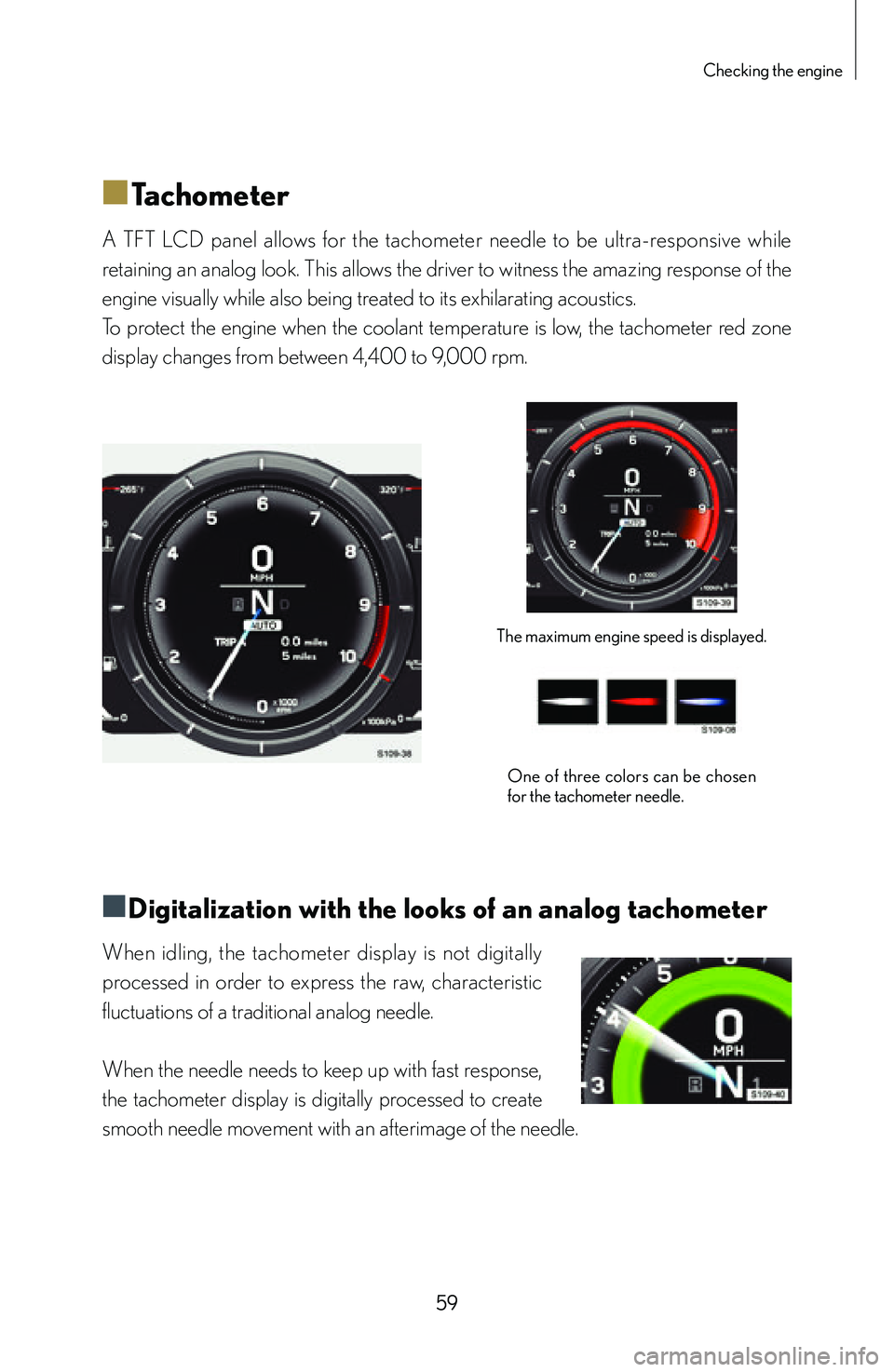
A TFT LCD panel allows for the tachometer needle to be ultra-responsive while
retaining an analog look. This allows the driver to witness the amazing response of the
engine visually while also being treated to its exhilarating acoustics.
To protect the engine when the coolant temperature is low, the tachometer red zone
display changes from between 4,400 to 9,000 rpm.
The maximum engine speed is displayed.
One of three colors can be chosen
for the tachometer needle.
■
■Digitalization with the looks of an analog tachometer
When idling, the tachometer display is not digitally
processed in order to express the raw, characteristic
fluctuations of a traditional analog needle.
When the needle needs to keep up with fast response,
the tachometer display is digitally processed to create
smooth needle movement with an afterimage of the needle.
Page 63 of 128

61
Checking the engine
■
■Engine oil temperature gauge
The engine oil temperature gauge displays the oil temperature from 100 to 320°F
(40 to 160°C). When the oil temperature exceeds 284°F (140°C), a buzzer will
sound and the bar display will blink in red and white to inform the driver that the
oil temperature is abnormally high and that the performance and lifespan of the
oil is severely compromised. Allowing the engine oil to cool and maintain a stable
temperature helps to stabilize its performance.
During high-speed driving: approximately 176
to 194°F (80 to 90°C)
[Outside air temperature approximately 68°F
(20°C)]Blinks when temperature exceeds
284°F (140°C)
An oil temperature sensor is installed near the oil filter to monitor the temperature
of the engine oil supplied by the oil pump. The ECU processes the engine oil
temperature from this sensor and informs the driver using the engine oil temperature
gauge.
Page 64 of 128

62
■
■Engine oil pressure gauge
The engine oil pressure gauge displays the engine oil pressure from 0 to 800
kPa. The rapid response of the TFT LCD panel allows for the fluctuations in engine
oil pressure that occur with engine speed to be displayed instantly. The engine oil
pressure is also affected by other factors such as engine oil type, temperature and
deterioration. If the engine oil pressure is too low, the master warning light comes on
and the “Engine oil pressure low” warning message is displayed. Checking the engine
oil pressure regularly aids understanding of the condition of the engine and engine oil.
During high-speed driving: approximately 400
to 800 kPa
(changes depending on driving conditions)
[Outside air temperature approximately 68°F
(20°C)]
When oil pressure is insufficient
An oil pressure sensor is installed near the oil filter.
The oil pressure measurements are processed by the ECU and displayed by the
engine oil pressure gauge.
Page 81 of 128
79
Maintaining the vehicle’s exterior
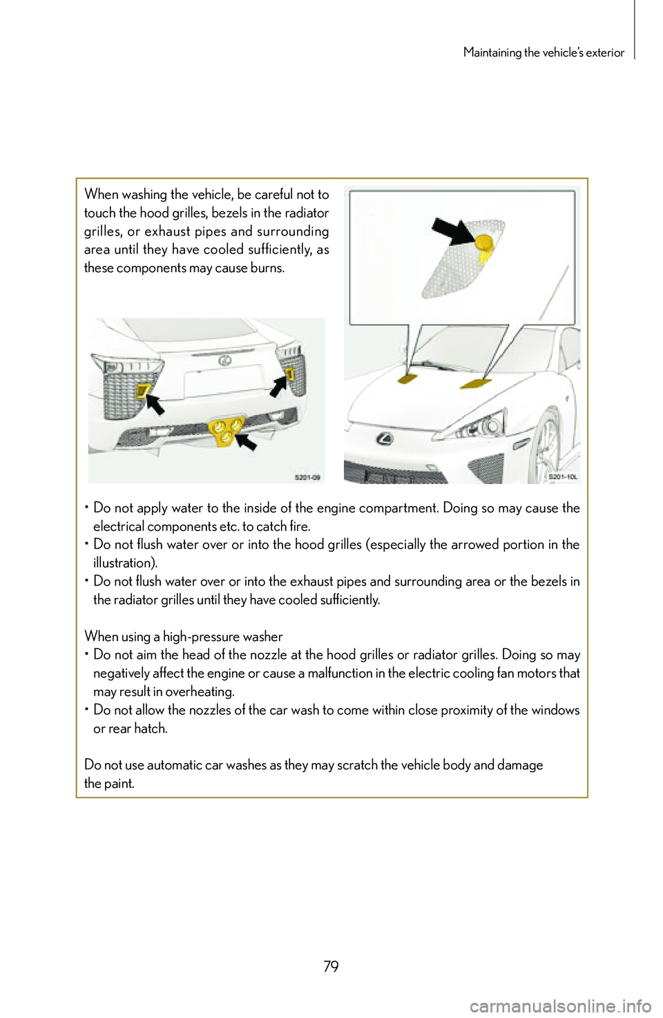
When washing the vehicle, be careful not to
touch the hood grilles, bezels in the radiator
grilles, or exhaust pipes and surrounding
area until they have cooled sufficiently, as
these components may cause burns.
• Do not apply water to the inside of the engine compartment. Doing so may cause the
electrical components etc. to catch fire.
• Do not flush water over or into the hood grilles (especially the arrowed portion in the
illustration).
• Do not flush water over or into the exhaust pipes and surrounding area or the bezels in
the radiator grilles until they have cooled sufficiently.
When using a high-pressure washer
• Do not aim the head of the nozzle at the hood grilles or radiator grilles. Doing so may
negatively affect the engine or cause a malfunction in the electric cooling fan motors that
may result in overheating.
• Do not allow the nozzles of the car wash to come within close proximity of the windows
or rear hatch.
Do not use automatic car washes as they may scratch the vehicle body and damage
the paint.
Page 88 of 128
86
■
■Maintaining the CFRP (Carbon Fiber Reinforced
Plastics) areas
Some interior components such as the instrument panel and rear hatch are made
from the same CFRP material as the main body shell. These exposed components
feature a deep and three-dimensional presence with a special clear coating.
Additionally, panels underneath the windows have a matte coating to prevent glare
and reflections.
■
■Daily maintenance
For cleaning, follow the procedure below:
1 Wipe dirty surfaces with a dampened soft cloth or synthetic chamois.
2 Wipe away any remaining moisture with a soft, dry cloth.
• Do not rub the matte coated surfaces strongly as doing so may damage the surface or
cause it to shine.
• Do not use wax, polish or polishing cleaners. Especially use caution around the
instrument panel, as improper care may cause the instrument panel to reflect off of the
windshield, obstructing the driver's front view.
Page 117 of 128
115
Index
Checking the oil level 69
Clock 67
Clutch 37
Clutch disc 37
Cold starting restrictions 17
Combination meter 57
Connecting an external battery
to start the engine 98
Control characteristics
depending on driving mode 23
Control pad 66
Coolant temperature 60
Coolant temperature gauge 60
Crankshaft 38
Creep phenomenon 37
DDark current (parasitic current) 93
Dead battery 94
Default shift speed setting 41
Departure angle 100
Diaphragm spring 37
Differential 39
Differential oil cooler 39
Digital display 56
Disabling the theft deterrent
system 102
Disabling the tilt sensor 102
Discharged battery 94
Disconnecting the negative (-)
battery terminal 99
Door mirror switches 9
Double wishbone front
suspension 47
Downshift 40
Driving mode 58
Driving mode selection 27
Driving mode selector switch 41
Driving mode selector switch
operation 23
Driving mode-linked variable
throttle response 33
Driving position 20
Driving position adjustment 10
Dry single-plate clutch 37
Dual shaft transmission 39
EECB (Electronically
Controlled Brake) 50
Emergency brake 9
Engine 56
Engine code 16
Engine coolant 60
Engine coolant temperature
gauge 60
Engine coolant temperature
sensor 60
Engine limiters 16
Engine oil pressure 62
Engine oil pressure gauge 62
Engine oil temperature gauge 61
Engine overspeed 70
Engine protection mechanisms 16
Page 118 of 128
116
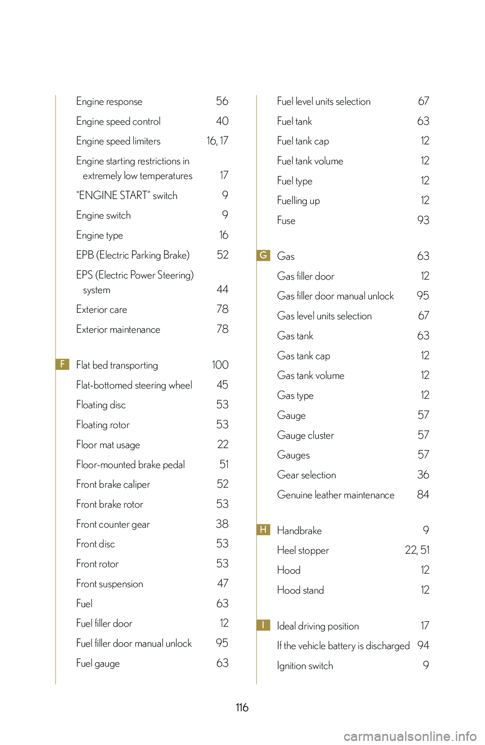
Engine response 56
Engine speed control 40
Engine speed limiters 16, 17
Engine starting restrictions in
extremely low temperatures 17
“ENGINE START” switch 9
Engine switch 9
Engine type 16
EPB (Electric Parking Brake) 52
EPS (Electric Power Steering)
system 44
Exterior care 78
Exterior maintenance 78
FFlat bed transporting 100
Flat-bottomed steering wheel 45
Floating disc 53
Floating rotor 53
Floor mat usage 22
Floor-mounted brake pedal 51
Front brake caliper 52
Front brake rotor 53
Front counter gear 38
Front disc 53
Front rotor 53
Front suspension 47
Fuel 63
Fuel filler door 12
Fuel filler door manual unlock 95
Fuel gauge 63
Fuel level units selection 67
Fuel tank 63
Fuel tank cap 12
Fuel tank volume 12
Fuel type 12
Fuelling up 12
Fuse 93
GGas 63
Gas filler door 12
Gas filler door manual unlock 95
Gas level units selection 67
Gas tank 63
Gas tank cap 12
Gas tank volume 12
Gas type 12
Gauge 57
Gauge cluster 57
Gauges 57
Gear selection 36
Genuine leather maintenance 84
HHandbrake 9
Heel stopper 22, 51
Hood 12
Hood stand 12
IIdeal driving position 17
If the vehicle battery is discharged 94
Ignition switch 9
Page 121 of 128
119
Index
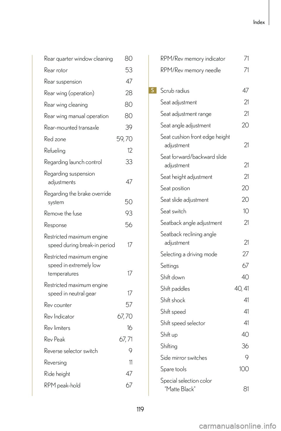
Rear quarter window cleaning 80
Rear rotor 53
Rear suspension 47
Rear wing (operation) 28
Rear wing cleaning 80
Rear wing manual operation 80
Rear-mounted transaxle 39
Red zone 59, 70
Refueling 12
Regarding launch control 33
Regarding suspension
adjustments 47
Regarding the brake override
system 50
Remove the fuse 93
Response 56
Restricted maximum engine
speed during break-in period 17
Restricted maximum engine
speed in extremely low
temperatures 17
Restricted maximum engine
speed in neutral gear 17
Rev counter 57
Rev Indicator 67 , 70
Rev limiters 16
Rev Peak 67 , 71
Reverse selector switch 9
Reversing 11
Ride height 47
RPM peak-hold 67
RPM/Rev memory indicator 71
RPM/Rev memory needle 71
SScrub radius 47
Seat adjustment 21
Seat adjustment range 21
Seat angle adjustment 20
Seat cushion front edge height
adjustment 21
Seat forward/backward slide
adjustment 21
Seat height adjustment 21
Seat position 20
Seat slide adjustment 20
Seat switch 10
Seatback angle adjustment 21
Seatback reclining angle
adjustment 21
Selecting a driving mode 27
Settings 67
Shift down 40
Shift paddles 40, 4 1
Shift shock 41
Shift speed 41
Shift speed selector 41
Shift up 40
Shifting 36
Side mirror switches 9
Spare tools 100
Special selection color
“Matte Black” 81
Page 122 of 128
120
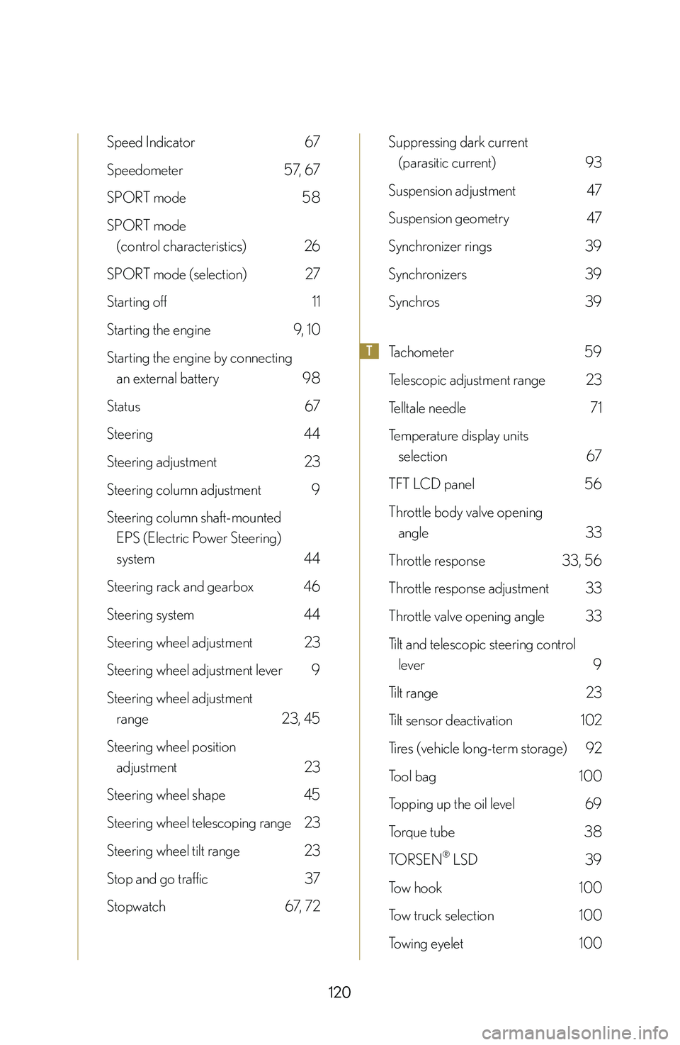
Speed Indicator 67
Speedometer 57, 67
SPORT mode 58
SPORT mode
(control characteristics) 26
SPORT mode (selection) 27
Starting off 11
Starting the engine 9, 1 0
Starting the engine by connecting
an external battery 98
Status 67
Steering 44
Steering adjustment 23
Steering column adjustment 9
Steering column shaft-mounted
EPS (Electric Power Steering)
system 44
Steering rack and gearbox 46
Steering system 44
Steering wheel adjustment 23
Steering wheel adjustment lever 9
Steering wheel adjustment
range 23, 45
Steering wheel position
adjustment 23
Steering wheel shape 45
Steering wheel telescoping range 23
Steering wheel tilt range 23
Stop and go traffic 37
Stopwatch 67 , 72
Suppressing dark current
(parasitic current) 93
Suspension adjustment 47
Suspension geometry 47
Synchronizer rings 39
Synchronizers 39
Synchros 39
TTachometer 59
Telescopic adjustment range 23
Telltale needle 71
Temperature display units
selection 67
TFT LCD panel 56
Throttle body valve opening
angle 33
Throttle response 33, 56
Throttle response adjustment 33
Throttle valve opening angle 33
Tilt and telescopic steering control
lever 9
Tilt range 23
Tilt sensor deactivation 102
Tires (vehicle long-term storage) 92
Tool bag 100
Topping up the oil level 69
Torque tube 38
TORSEN® LSD 39
Tow hook 100
Tow truck selection 100
Towing eyelet 100