engine lexus LFA 2012 Technical Information / LEXUS 2012 LFA: INSIDE THE LFA
[x] Cancel search | Manufacturer: LEXUS, Model Year: 2012, Model line: LFA, Model: Lexus LFA 2012Pages: 128, PDF Size: 5.91 MB
Page 38 of 128
36
Shifting
With regards to the drivetrain, the steering wheel-mounted paddle shift switches
command the automated dry single-plate clutch and rear-mounted ASG (Automated
Sequential Gearbox) transaxle. This fully automated configuration allows the driver to
upshift (+) or downshift (-) while keeping both hands on the steering wheel.
When the driver initiates a gear change using the paddle shift switches, the ASG
computer automatically controls and coordinates clutch engagement, engine speed,
torque transfer and gear select and shift operations.
The engine-mounted dr y single-plate clutch and rear-mounted transaxle are
connected via torque tube to provide the direct feel of a manual gearbox.
The ECU manages gear changes to provide intuitive response to the driver ’s
a c c e l e r a t i o n d e m a n d s . D o i n g s o a l l o w s g e a r c h a n g e s t o b e c a r r i e d o u t
instantaneously, providing a nearly uninterrupted flow of power. The engine speed
is computer controlled on upshifts and downshifts in order to ensure smooth clutch
engagement.
Naturally, shifting can be accomplished manually via the paddle shift switches.
However, shifting can also be performed automatically in AUTO mode. Switching to a
different driving mode using the driving mode selector switch or operating the paddle
shift switches will resume manual operation.
When in a manually shifted driving mode, the shift speeds may be tailored to the
driver’s preferences. Using the shift speed selector, the shift speed can be adjusted in
7 stages to a minimum shift time of approximately 0.15 seconds.
Page 39 of 128
37
Shifting
■
■Dry single-plate clutch
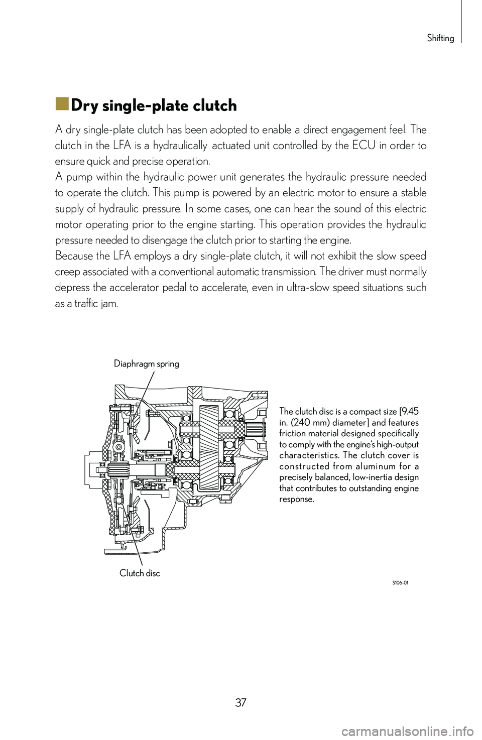
A dry single-plate clutch has been adopted to enable a direct engagement feel. The
clutch in the LFA is a hydraulically
actuated unit controlled by the ECU in order to
ensure quick and precise operation.
A pump within the hydraulic power unit generates the hydraulic pressure needed
to operate the clutch. This pump is powered by an electric motor to ensure a stable
supply of hydraulic pressure. In some cases, one can hear the sound of this electric
motor operating prior to the engine starting. This operation provides the hydraulic
pressure needed to disengage the clutch prior to starting the engine.
Because the LFA employs a dry single-plate clutch, it will not exhibit the slow speed
creep associated with a conventional automatic transmission. The driver must normally
depress the accelerator pedal to accelerate, even in ultra-slow speed situations such
as a traffic jam.
Diaphragm spring
Clutch disc The clutch disc is a compact size [9.45
in. (240 mm) diameter] and features
friction material designed specifically
to comply with the engine’s high-output
characteristics. The clutch cover is
c o n s t r u c t e d f r o m a l u m i n u m f o r a
precisely balanced, low-inertia design
that contributes to outstanding engine
response.
Page 40 of 128
38
■
■Torque tube
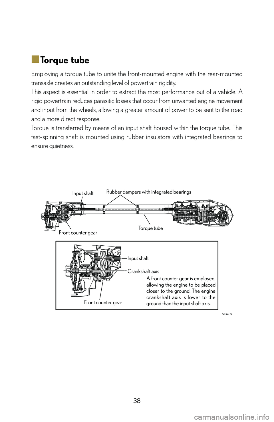
Employing a torque tube to unite the front-mounted engine with the rear-mounted
transaxle creates an outstanding level of powertrain rigidity.
This aspect is essential in order to extract the most performance out of a vehicle. A
rigid powertrain reduces parasitic losses that occur from unwanted engine movement
and input from the wheels, allowing a greater amount of power to be sent to the road
and a more direct response.
Torque is transferred by means of an input shaft housed within the torque tube. This
fast-spinning shaft is mounted using rubber insulators with integrated bearings to
ensure quietness.
Torque tube
Rubber dampers with integrated bearings
Input shaft
Front counter gear Input shaft
A front counter gear is employed,
allowing the engine to be placed
closer to the ground. The engine
crankshaf t axis is lower to the
ground than the input shaft axis.
Crankshaft axis
Front counter gear
Page 41 of 128
39
Shifting
■
■Rear transaxle
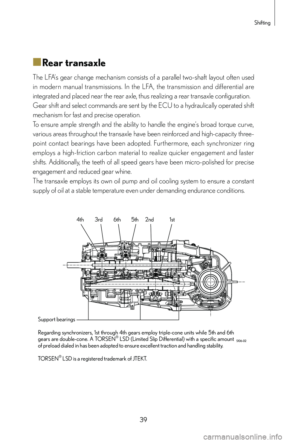
The LFA’s gear change mechanism consists of a parallel two-shaft layout often used
in modern manual transmissions. In the LFA, the transmission and differential are
integrated and placed near the rear axle, thus realizing a rear transaxle configuration.
Gear shift and select commands are sent by the ECU to a hydraulically operated shift
mechanism for fast and precise operation.
To ensure ample strength and the ability to handle the engine’s broad torque curve,
various areas throughout the transaxle have been reinforced and high-capacity three-
point contact bearings have been adopted. Furthermore, each synchronizer ring
employs a high-friction carbon material to realize quicker engagement and faster
shifts. Additionally, the teeth of all speed gears have been micro-polished for precise
engagement and reduced gear whine.
The transaxle employs its own oil pump and oil cooling system to ensure a constant
supply of oil at a stable temperature even under demanding endurance conditions.
3rd 6th 5th 2nd 1st
Support bearings
Regarding synchronizers, 1st through 4th gears employ triple-cone units while 5th and 6th
gears are double-cone. A TORSEN
® LSD (Limited Slip Differential) with a specific amount
of preload dialed in has been adopted to ensure excellent traction and handling stability.
TORSEN
® LSD is a registered trademark of JTEKT. 4th
Page 42 of 128
40
■
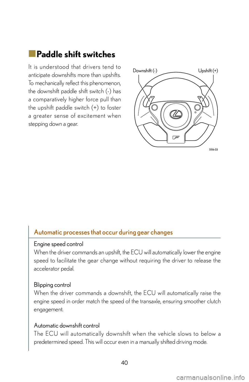
■Paddle shift switches
I t i s u n d e rs t o o d t h a t d r i ve rs t e n d t o
anticipate downshifts more than upshifts.
To mechanically reflect this phenomenon,
the downshift paddle shift switch (-) has
a comparatively higher force pull than
the upshift paddle switch (+) to foster
a g re a t e r s e n s e o f exc i t e m e n t w h e n
stepping down a gear.
Automatic processes that occur during gear changes
Engine speed control
When the driver commands an upshift, the ECU will automatically lower the engine
speed to facilitate the gear change without requiring the driver to release the
accelerator pedal.
Blipping control
When the driver commands a downshift, the ECU will automatically raise the
engine speed in order match the speed of the transaxle, ensuring smoother clutch
engagement.
Automatic downshift control
The ECU will au tomatically downshif t when the vehicle slows to below a
predetermined speed. This will occur even in a manually shifted driving mode.
Downshift (-) Upshift (+)
Page 52 of 128

50
Braking
The LFA is equipped with an ECB (Electronically Controlled Brake) system.
When the brake pedal is depressed, information on how much force is being used to
depress the pedal and the amount it is depressed is sent to the ECB computer. This
computer takes into account the vehicle’s overall condition using inputs from various
sensors and distributes the optimal amount of brake force to each individual wheel.
The ECB system uses an electric pump to generate hydraulic pressure, thereby
providing braking power without relying on engine vacuum. The use of this
technology ensures a consistent supply of effective braking power.
However, the detail behind the LFA brake system does not end with the ECB system.
Monoblock calipers and CCM (Carbon Ceramic Material) discs are just a few of the
other components that give the LFA its generous braking power. Furthermore, large
brake ducts have been proactively integrated in order to feed the brakes fresh, cold
air to keep them working at their optimum temperature for consistent performance.
Regarding the brake override system:
If the driver depresses the brake and accelerator pedals at the same time or if
the ECU judges that both acceleration and braking commands are being issued,
braking will be prioritized. The system will ignore the signal from the accelerator
pedal, close all throttle valves and provide the appropriate amount of braking force
demanded by the driver’s braking effort.
Page 58 of 128

56
Checking the engine
Components expected to operate at high speeds have been made as light and
precise as possible, realizing a superfast engine capable of revving from idle to 9,000
rpm in only 0.6 seconds.
In order to ensure adequate lubrication under high G-loads, a dry sump lubrication
system has been adopted.
The engine oil is cooled by a liquid-cooled oil cooler located in the valley between
each bank of cylinders and an air-cooled oil cooler housed within the front overhang.
In addition, two high-per formance radiators have been housed within the rear
overhang for an optimal front-rear weight balance.
A TFT LCD panel has been adopted to accurately transmit various information from
the engine to the driver. An analog-style digital tachometer displays engine speed
while other real-time engine information is displayed digitally for both superior visual
clarity and response.
An acrylic lens with a metal ring is positioned at the center of the meter to clearly
display the primary instruments and to create a three-dimensional appearance.
Page 59 of 128
57
Checking the engine
■
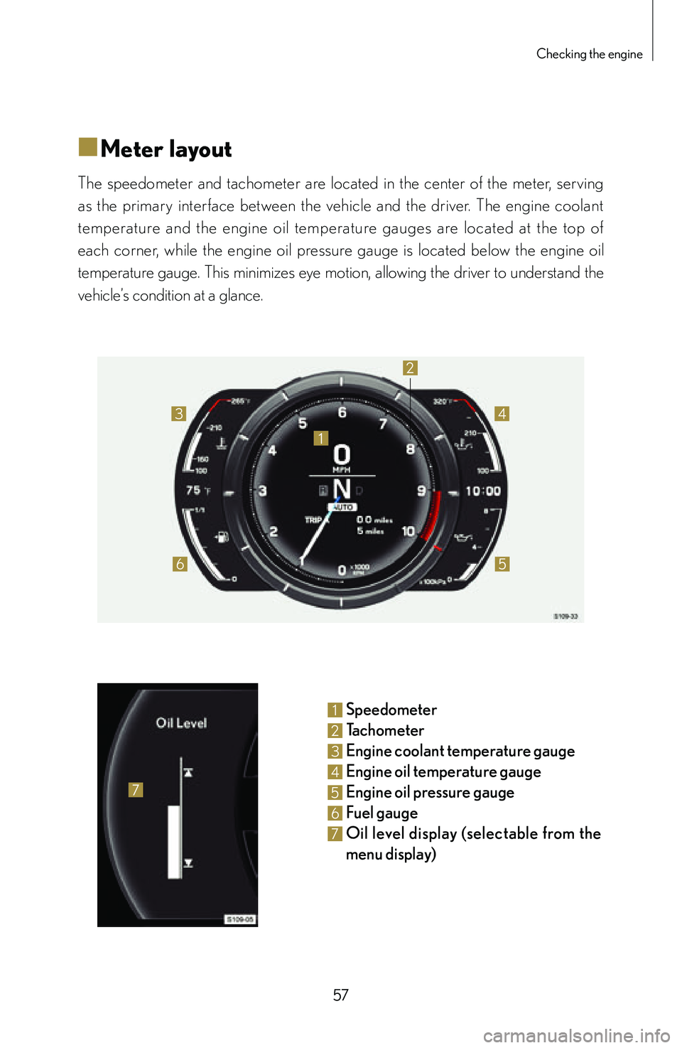
■Meter layout
The speedometer and tachometer are located in the center of the meter, serving
as the primary interface between the vehicle and the driver. The engine coolant
temperature and the engine oil temperature gauges are located at the top of
each corner, while the engine oil pressure gauge is located below the engine oil
temperature gauge. This minimizes eye motion, allowing the driver to understand the
vehicle’s condition at a glance.
1
2
3
65
4
7
1 Speedometer
2 Tachometer
3 Engine coolant temperature gauge
4 Engine oil temperature gauge
5 Engine oil pressure gauge
6 Fuel gauge
7 Oil level display (s electable fr om th e
menu display)
Page 60 of 128
58
■
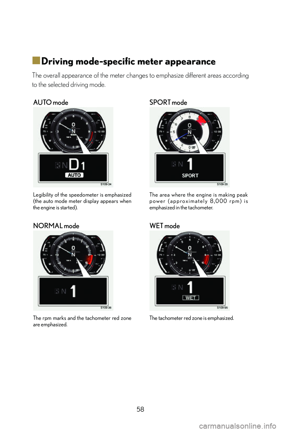
■Driving mode-specific meter appearance
The overall appearance of the meter changes to emphasize different areas according
to the selected driving mode.
AUTO mode
Legibility of the speedometer is emphasized
(the auto mode meter display appears when
the engine is started).
SPORT mode
The area where the engine is making peak
p o w e r ( a p p r o x i m a t e l y 8 , 0 0 0 r p m ) i s
emphasized in the tachometer.
NORMAL mode
The rpm marks and the tachometer red zone
are emphasized.
WET mode
The tachometer red zone is emphasized.
Page 61 of 128
59
Checking the engine
■
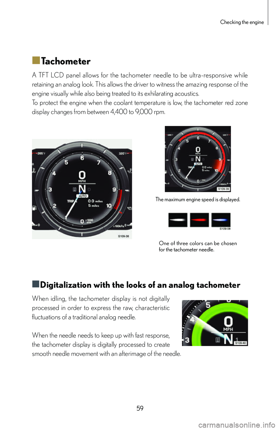
■Tachometer
A TFT LCD panel allows for the tachometer needle to be ultra-responsive while
retaining an analog look. This allows the driver to witness the amazing response of the
engine visually while also being treated to its exhilarating acoustics.
To protect the engine when the coolant temperature is low, the tachometer red zone
display changes from between 4,400 to 9,000 rpm.
The maximum engine speed is displayed.
One of three colors can be chosen
for the tachometer needle.
■
■Digitalization with the looks of an analog tachometer
When idling, the tachometer display is not digitally
processed in order to express the raw, characteristic
fluctuations of a traditional analog needle.
When the needle needs to keep up with fast response,
the tachometer display is digitally processed to create
smooth needle movement with an afterimage of the needle.