sensor lexus LFA 2012 Technical Information / LEXUS 2012 LFA: INSIDE THE LFA
[x] Cancel search | Manufacturer: LEXUS, Model Year: 2012, Model line: LFA, Model: Lexus LFA 2012Pages: 128, PDF Size: 5.91 MB
Page 31 of 128
29
Operating the driving mode selector switch
■
■VDIM
The LFA employs VDIM (Vehicle Dynamics Integrated Management), a dynamic
control program that integrates braking and drive torque control to help ensure
overall vehicle stability and secure handling. VDIM also features vertical acceleration
and roll rate sensors, added exclusively for the LFA. The addition of these sensors
increases the precision and response of road camber estimation on banked roads,
such as “The Carousel” at the Nürburgring, to determine the vehicle’s performance
limits. This prevents excessive intervention on banked roads.
The LFA’s VDIM system allows for two individual control modes selected by the driver
using the driving mode selector switch.
When in SPORT mode, VDIM control is modified in order to enhance driving
pleasure and the driver’s confidence in the vehicle.
When not in SPORT mode, VDIM returns to NORMAL mode, designed to intervene
seamlessly as the vehicle reaches its performance limits, thereby realizing smoother
driving dynamics.
This helps ensure both overall vehicle stability and secure handling.
Page 34 of 128
32
When the driver depresses the accelerator pedal, a signal is sent to the ECU where
it is interpreted and used to control the throttle valve angle. This is all performed
electronically without a conventional cable linkage.
The throttle valves are opened and closed by a pair of electric motors, one for each
bank of cylinders. There are a total of 10 individual throttle valves, one for each
cylinder. This configuration minimizes the amount of air between each combustion
chamber and its corresponding independent throttle valve, promoting instantaneous
throttle action for outstanding engine response.
Furthermore, this drive-by-wire technology is able to tailor specific throttle valve
angle strategies to each available driving mode. Depending on which driving mode
is selected, depressing the accelerator pedal the same amount will result in a different
throttle valve angle. This variable control results in engine characteristics better suited
to the driver’s intentions and driving conditions.
■
■Accelerator pedal mechanism
A f l o o r- m o u n t e d a c c e l e r a t o r p e d a l
allows the fulcrum to be moved closer to
the floor and the driver's heel. Depressing
the pedal actuates a rod, which moves
through a sensor. The pedal has a 1.48 in.
(37.7 mm) stroke and the sensor is able
to precisely detect movement down to
0.03 in. (0.8 mm) in order to provide a
more direct feel.
Pedal stroke
Fulcrum
Accelerator pedal (Position sensor judgment)
Pedal
released Pedal
fully
depressed 0 1.48 (37.7)
Pedal stroke [in. (mm)]
Accelerating
Page 52 of 128

50
Braking
The LFA is equipped with an ECB (Electronically Controlled Brake) system.
When the brake pedal is depressed, information on how much force is being used to
depress the pedal and the amount it is depressed is sent to the ECB computer. This
computer takes into account the vehicle’s overall condition using inputs from various
sensors and distributes the optimal amount of brake force to each individual wheel.
The ECB system uses an electric pump to generate hydraulic pressure, thereby
providing braking power without relying on engine vacuum. The use of this
technology ensures a consistent supply of effective braking power.
However, the detail behind the LFA brake system does not end with the ECB system.
Monoblock calipers and CCM (Carbon Ceramic Material) discs are just a few of the
other components that give the LFA its generous braking power. Furthermore, large
brake ducts have been proactively integrated in order to feed the brakes fresh, cold
air to keep them working at their optimum temperature for consistent performance.
Regarding the brake override system:
If the driver depresses the brake and accelerator pedals at the same time or if
the ECU judges that both acceleration and braking commands are being issued,
braking will be prioritized. The system will ignore the signal from the accelerator
pedal, close all throttle valves and provide the appropriate amount of braking force
demanded by the driver’s braking effort.
Page 62 of 128
60
■
■Engine coolant temperature gauge
The engine coolant temperature gauge displays the coolant temperature between
100 and 265°F (40 and 130°C). When the coolant temperature exceeds 244°F
(118°C), a buzzer will sound and the bar display will blink in red and white to inform
the driver of abnormally high coolant temperatures.
During high-speed driving: approximately 176
to 194°F (80 to 90°C)
Idling: approximately 203°F (95°C)
[Outside air temperature approximately 68°F
(20°C)]Blinks when temperature exceeds
244°F (118°C)
Each bank of cylinders has its own engine coolant temperature sensor. The ECU
calculates the engine coolant temperature from both of these sensors and informs the
driver using the engine coolant temperature gauge.
Page 63 of 128

61
Checking the engine
■
■Engine oil temperature gauge
The engine oil temperature gauge displays the oil temperature from 100 to 320°F
(40 to 160°C). When the oil temperature exceeds 284°F (140°C), a buzzer will
sound and the bar display will blink in red and white to inform the driver that the
oil temperature is abnormally high and that the performance and lifespan of the
oil is severely compromised. Allowing the engine oil to cool and maintain a stable
temperature helps to stabilize its performance.
During high-speed driving: approximately 176
to 194°F (80 to 90°C)
[Outside air temperature approximately 68°F
(20°C)]Blinks when temperature exceeds
284°F (140°C)
An oil temperature sensor is installed near the oil filter to monitor the temperature
of the engine oil supplied by the oil pump. The ECU processes the engine oil
temperature from this sensor and informs the driver using the engine oil temperature
gauge.
Page 64 of 128

62
■
■Engine oil pressure gauge
The engine oil pressure gauge displays the engine oil pressure from 0 to 800
kPa. The rapid response of the TFT LCD panel allows for the fluctuations in engine
oil pressure that occur with engine speed to be displayed instantly. The engine oil
pressure is also affected by other factors such as engine oil type, temperature and
deterioration. If the engine oil pressure is too low, the master warning light comes on
and the “Engine oil pressure low” warning message is displayed. Checking the engine
oil pressure regularly aids understanding of the condition of the engine and engine oil.
During high-speed driving: approximately 400
to 800 kPa
(changes depending on driving conditions)
[Outside air temperature approximately 68°F
(20°C)]
When oil pressure is insufficient
An oil pressure sensor is installed near the oil filter.
The oil pressure measurements are processed by the ECU and displayed by the
engine oil pressure gauge.
Page 65 of 128

63
Checking the engine
■
■Fuel gauge
The fuel gauge displays the amount of fuel remaining on a scale of 0 to 1/1. The
saddle-shaped fuel tank consists of a main tank compartment and a sub-tank
compartment. When the fuel level drops to approximately 2.9 gal. (11 L, 2.4 Imp. gal.)
between both compartments, the bar display will blink in amber to inform the driver
that the remaining fuel level is low. In this state, the remaining amount of fuel is directed
into the main tank compartment in order to ensure a stable supply of fuel to the engine
even under high cornering G-loads.
S109-14Main tank
compartment Sub-tank compartment
Fuel
Remaining fuel directed to main tank
compartment
Blinks when remaining fuel drops to approx. 2.9 gal. (11 L, 2.4 Imp. gal.)
The main tank compar tment and sub-tank compar tment each have their own
individual sender gauges to monitor the fuel levels. The ECU calculates the total
amount of fuel remaining from both of these sensors and informs the driver using
the fuel gauge. The ECU digitally processes the fuel level data in order to display a
clear and accurate fuel level even when the fuel level fluctuates under high cornering
G-loads.
Page 70 of 128

68
■
■Oil level
An oil level sensor is installed in the oil tank to measure the amount of oil present. The
reading from this sensor is displayed to the driver. This allows the engine oil level to
be checked simply by operating the control pad, without needing to get out of the
vehicle.
■
■Measurement
1 Select “Status”2 Select “Oil Level”
3 Displays
measur
ement result
Measurement is possible when the following
conditions are met:
1. Engine oil temperature: Between 203 and
230 °F (95 and 110°C)
2. Engine speed: Between 900 and 1, 100 rpm
3. Vehicle status: Stationary and idling
4. Vehicle level: Allowable inclination of 4 degrees
or less.
Example of display when
conditions are not met
Page 104 of 128
102
7 Select Neutral, engage the parking
brake, and turn the ignition switch to
the “LOCK” position.
8 When the LFA is completely loaded
onto the transport vehicle, secure it
with tire belts and chocks.
Be careful not to damage the tires with the
edge of the chocks.
Disabling the tilt sensor
If the tilt sensor is left on when loading the LFA onto a transport vehicle, the auto
alarm may activate.
1 Stop the engine and remove the
key.
2 Press the tilt sensor cancel switch
located inside the glove box.
3 While the indicator is flashing faster
than normal, close all the doors and
lock the vehicle using the wireless
remote control.
Page 117 of 128
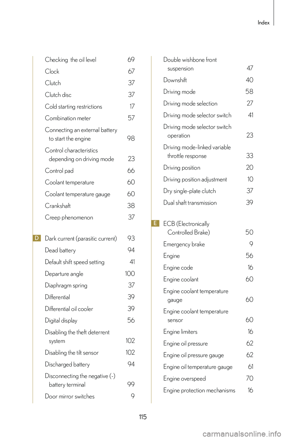
115
Index
Checking the oil level 69
Clock 67
Clutch 37
Clutch disc 37
Cold starting restrictions 17
Combination meter 57
Connecting an external battery
to start the engine 98
Control characteristics
depending on driving mode 23
Control pad 66
Coolant temperature 60
Coolant temperature gauge 60
Crankshaft 38
Creep phenomenon 37
DDark current (parasitic current) 93
Dead battery 94
Default shift speed setting 41
Departure angle 100
Diaphragm spring 37
Differential 39
Differential oil cooler 39
Digital display 56
Disabling the theft deterrent
system 102
Disabling the tilt sensor 102
Discharged battery 94
Disconnecting the negative (-)
battery terminal 99
Door mirror switches 9
Double wishbone front
suspension 47
Downshift 40
Driving mode 58
Driving mode selection 27
Driving mode selector switch 41
Driving mode selector switch
operation 23
Driving mode-linked variable
throttle response 33
Driving position 20
Driving position adjustment 10
Dry single-plate clutch 37
Dual shaft transmission 39
EECB (Electronically
Controlled Brake) 50
Emergency brake 9
Engine 56
Engine code 16
Engine coolant 60
Engine coolant temperature
gauge 60
Engine coolant temperature
sensor 60
Engine limiters 16
Engine oil pressure 62
Engine oil pressure gauge 62
Engine oil temperature gauge 61
Engine overspeed 70
Engine protection mechanisms 16