ESP LEXUS LS500H 2020 Repair Manual
[x] Cancel search | Manufacturer: LEXUS, Model Year: 2020, Model line: LS500H, Model: LEXUS LS500H 2020Pages: 516, PDF Size: 10.38 MB
Page 430 of 516

4287-2. Steps to take in an emergency
WARNING
As an added safety feature, your vehicle
has been equipped with a tire pressure
monitoring system (TPMS-tire pressure
warning system) that illuminates a low
tire pressure telltale (tire pressure warn-
ing light) when one or more of your tires
is significantly under-inflated. Accord-
ingly, when the low tire pressure telltale
(tire pressure warnin g light) illuminates,
you should stop and check your tires as
soon as possible, and inflate them to the
proper pressure. Driving on a signifi-
cantly under-inflated tire causes the tire
to overheat and can lead to tire failure.
Under-inflation also reduces fuel effi-
ciency and tire tread life, and may affect
the vehicle’s handling and stopping abil-
ity.
Please note that the TPMS (tire pressure
warning system) is not a substitute for
proper tire maintenance, and it is the
driver’s responsibility to maintain correct
tire pressure, even if under-inflation has
not reached the level to trigger illumina-
tion of the TPMS low tire pressure telltale
(tire pressure warning light).
Your vehicle has also been equipped with
a TPMS (tire pressure warning system)
malfunction indicator to indicate when
the system is not operating properly. The
TPMS (tire pressure warning system)
malfunction indicator is combined with
the low tire pressure telltale (tire pres-
sure warning light). When the system
detects a malfunction, the telltale will
flash for approximately one minute and
then remain continuously illuminated.
This sequence will continue upon subse-
quent vehicle start-ups as long as the
malfunction exists. When the malfunction
indicator is illuminated, the system may
not be able to detect or signal low tire
pressure as intended.TPMS (tire pressure warning system)
malfunctions may occur for a variety of
reasons, including the installation of
replacement or alternate tires or wheels
on the vehicle that prevent the TPMS
(tire pressure warning system) from func-
tioning properly. Always check the
TPMS (tire pressure warning system)
malfunction telltale after replacing one
or more tires or wheels on your vehicle to
ensure that the replacement or alternate
tires and wheels allow the TPMS (tire
pressure warning system) to continue to
function properly.
NOTICE
■To ensure the tire pressure warning
system operates properly
Do not install tires with different specifi-
cations or makers, as the tire pressure
warning system may not operate prop-
erly.
Page 434 of 516

4327-2. Steps to take in an emergency
becomes available again.
■If “Front Camera Unavailable” or “Front
Camera Unavailable See Owner's
Manual” is displayed
The following systems may be suspended
until the problem shown in the message is
resolved. ( P.197, 203, 425)
●PCS (Pre-Collision system)
●LTA (Lane Tracing Assist)
●Dynamic radar cruise control with
full-speed range
●RSA (Road Sign Assist) (if equipped)
●AHB (Automatic High Beam)
■If “Maintenance Required Soon” is dis-
played
Indicates that all maintenance according to
the driven distance on the maintenance
schedule
* should be performed soon.
Comes on approximately 4500 miles
(7200 km) after the message has been
reset. If necessary, perform maintenance.
Please reset the message after the mainte-
nance is performed. ( P.368)
*: Refer to the separa te “Scheduled Main-
tenance” or “Owner’s Manual Supple-
ment” for the maintenance interval
applicable to your vehicle.
■If “Maintenance Required Visit Your
Dealer” is displayed
Indicates that all maintenance is required to
correspond to the driven distance on the
maintenance schedule
*.
Comes on approximately 5000 miles
(8000 km) after the message has been
reset. (The indicator will not work properly
unless the message ha s been reset.) Per-
form the necessary maintenance. Please
reset the message after the maintenance is
performed. ( P.368)
*: Refer to the separa te “Scheduled Main-
tenance” or “Owner’s Manual Supple-
ment” for the maintenance interval
applicable to your vehicle.
■If “Oil Maintenance Required Soon” is
displayed
Indicates that the engine oil should be
scheduled to be changed.
Check the engine oil an d change it if neces-
sary. After changing th e engine oil, make
sure to reset the message. ( P.381)
■If “Oil Maintenance Required” is dis-
played
Indicates that the engine oil should be
changed.
Check and change the en gine oil, and oil fil-
ter by your Lexus dealer. After changing the
engine oil, make sure to reset the message.
( P.381)
■If “Shift System Malfunction Driving
Unavailable” is displayed
There is a malfunction in the shift control
system. Have the vehicle inspected by your
Lexus dealer immediately.
■If a message that indicates the need for
the shift lever operation is displayed
To prevent the shift le ver from being oper-
ated incorrectly or the vehicle from moving
unexpectedly, a message that requires shift-
ing the shift position may be displayed on
the multi-information display. In that case,
follow the instruction of the message and
shift the shift position.
■If a message that indicates the need for
visiting your Lexus dealer is displayed
The system or part shown on the
multi-information display is malfunctioning.
Have the vehicle inspected by your Lexus
dealer immediately.
■If a message that indicates the need for
referring to Owner’ s Manual is dis-
played
●If any of the following messages are
shown on the multi-information display,
follow the instructions.
• “Engine Coolant Temp High” ( P.444)
•“Battery Low” ( P.439)
• “Transmission Fluid Temp High” ( P.169)
●If any of the following messages are
shown on the multi-info rmation display, it
may indicate a malf unction. Have the
vehicle inspected by your Lexus dealer
Page 444 of 516
4427-2. Steps to take in an emergency
as in heavy traffic.
■When the battery is removed or dis-
charged
●Information stored in the ECU is cleared.
When the battery is depleted, have the
vehicle inspected at your Lexus dealer.
●Some systems may require initialization.
( P.484)
■When removing the battery terminals
When the battery terminals are removed,
the information stored in the ECU is
cleared. Before removi ng the battery termi-
nals, contact your Lexus dealer.
■Charging the battery
The electricity stored in the battery will dis-
charge gradually even when the vehicle is
not in use, due to natural discharge and the
draining effects of certain electrical appli-
ances. If the vehicle is left for a long time,
the battery may discharge, and the engine
may be unable to start. (The battery
recharges automatically during driving.)
■When recharging or replacing the bat-
tery
●In some cases, it may not be possible to
unlock the doors using the smart access
system with push-button start when the
battery is discharged. Use the wireless
remote control or the mechanical key to
lock or unlock the doors.
●The engine may not start on the first
attempt after the battery has recharged
but will start normally after the second
attempt. This is not a malfunction.
●The engine switch mode is memorized by
the vehicle. When the battery is recon-
nected, the system will return to the
mode it was in before the battery was dis-
charged. Before di sconnecting the bat-
tery, turn the engine switch off.
If you are unsure what mode the engine
switch was in befo re the battery dis-
charged, be especially careful when
reconnecting the battery.
■When replacing the battery
●Use a Central Degassing type battery
(European Regulations).
●Use a battery with the same case size as the previous battery and an equivalent
20 hour rate capacity (20HR) or greater.
• If the sizes differ, the battery cannot be
properly secured.
• If the 20 hour rate capacity is low, even if the time period where the vehicle is not
used is a short time, the battery may dis-
charge and the engine may not be able to
start.
●Use a battery with a handle. If a battery
without a handle is used, removal is more
difficult.
●After replacing, firm ly attach the follow-
ing items to the exhaust hole of the bat-
tery.
• Use the exhaust hose that was attached
to the battery before replacing and con-
firm that it is firmly connected to the hole
section of the vehicle.
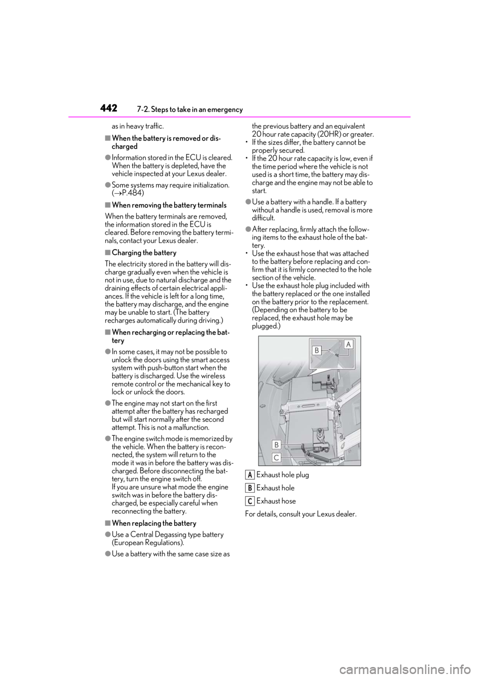
• Use the exhaust hole plug included with the battery replaced or the one installed
on the battery prior to the replacement.
(Depending on the battery to be
replaced, the exhaust hole may be
plugged.)
Exhaust hole plug
Exhaust hole
Exhaust hose
For details, consult your Lexus dealer.
A
B
C
Page 448 of 516
4467-2. Steps to take in an emergency
1Remove the engine compartment
cover.
2
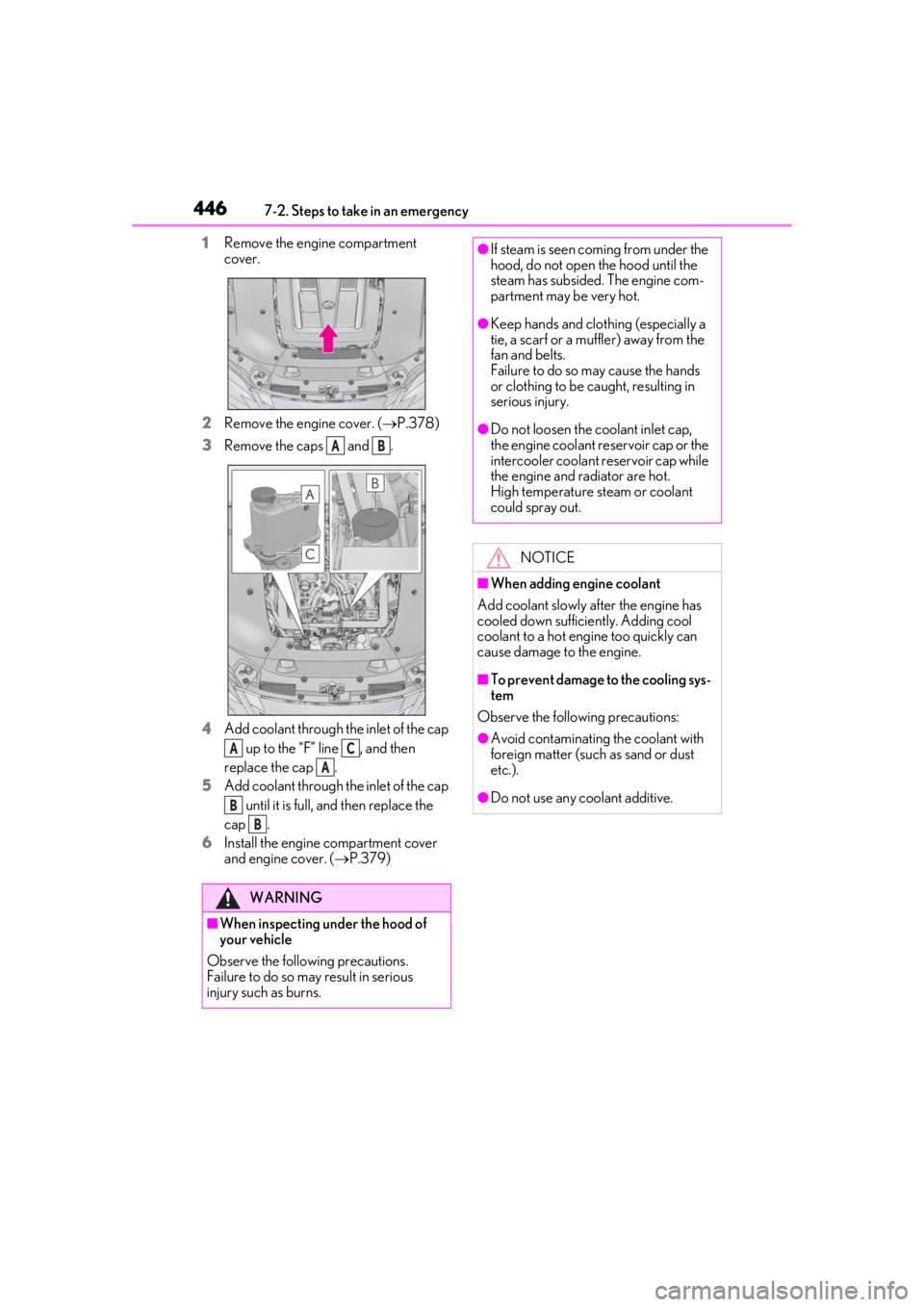
Remove the engine cover. ( P.378)
3
Remove the caps and .
4
Add coolant through the inlet of the cap up to the “F” line , and then
replace the cap .
5
Add coolant through the inlet of the cap
until it is full, and then replace the
cap .
6
Install the engine compartment cover
and engine cover. ( P.379)
WARNING
■When inspecting under the hood of
your vehicle
Observe the following precautions.
Failure to do so may result in serious
injury such as burns.
AB
AC
A
B
B
●If steam is seen coming from under the
hood, do not open the hood until the
steam has subsided. The engine com-
partment may be very hot.
●Keep hands and clothing (especially a
tie, a scarf or a muffler) away from the
fan and belts.
Failure to do so may cause the hands
or clothing to be caught, resulting in
serious injury.
●Do not loosen the coolant inlet cap,
the engine coolant reservoir cap or the
intercooler coolant reservoir cap while
the engine and radiator are hot.
High temperature steam or coolant
could spray out.
NOTICE
■When adding engine coolant
Add coolant slowly after the engine has
cooled down sufficiently. Adding cool
coolant to a hot engine too quickly can
cause damage to the engine.
■To prevent damage to the cooling sys-
tem
Observe the following precautions:
●Avoid contaminating the coolant with
foreign matter (such as sand or dust
etc.).
●Do not use any coolant additive.
Page 466 of 516
4648-1. Specifications
■Traction AA, A, B, C
The traction grades, from highest to
lowest, are AA, A, B and C, and they
represent the tire’s ability to stop on
wet pavement as measured under con-
trolled conditions on specified govern-
ment test surfaces of asphalt and
concrete.
A tire marked C may have poor traction
performance.
Warning: The traction grade assigned to
this tire is based on braking (straight
ahead) traction tests and does not include
cornering (turning) traction.
■Temperature A, B, C
The temperature grades are A (the
highest), B, and C, representing the
tire’s resistance to the generation of
heat and its ability to dissipate heat when tested under controlled condi-
tions on a specified indoor laboratory
test wheel.
Sustained high temperature can cause the
material of the tire to degenerate and
reduce tire life, and excessive temperature
can lead to sudd
en tire failure.
Grade C corresponds to a level of perfor-
mance which all passenger car tires must
meet under the Fede ral Motor Vehicle
Safety Standard No. 109.
Grades B and A represent higher levels of
performance on the laboratory test wheel
than the minimum required by law.
Warning: The temperature grades of a tire
assume that it is properly inflated and not
overloaded.
Excessive speed, unde rinflation, or exces-
sive loading, either separately or in combi-
nation, can cause heat buildup and
possible tire failure.
Glossary of tire terminology
Tire related termMeaning
Cold tire inflation pressure
Tire pressure when the vehicle has been parked for
three hours or more, or has not been driven more
than 1 mile or 1.5 km under that condition
Maximum inflation pressureThe maximum cold inflated pressure to which a tire
may be inflated, shown on the sidewall of the tire
Recommended inflation pressureCold tire inflation pressure recommended by a
manufacturer
Accessory weight
The combined weight (in excess of those standard
items which may be replaced) of automatic trans-
mission, power steering, power brakes, power win-
dows, power seats, radio and heater, to the extent
that these items are available as factory-installed
equipment (whether installed or not)
Page 468 of 516
4668-1. Specifications
Vehicle normal load on the tire
The load on an individual tire that is determined by
distributing to each axle its share of curb weight,
accessory weight, and normal occupant weight
(distributed in accor dance with Table 1
* below), and
dividing by two
Weather sideThe surface area of the rim not covered by the
inflated tire
Bead
The part of the tire that is made of steel wires,
wrapped or reinforced by ply cords and that is
shaped to fit the rim
Bead separationA breakdown of the bond between components in
the bead
Bias ply tire
A pneumatic tire in which the ply cords that extend
to the beads are laid at alternate angles substan-
tially less than 90 degrees to the centerline of the
tread
CarcassThe tire structure, except tread and sidewall rubber
which, when inflated, bears the load
ChunkingThe breaking away of pieces of the tread or sidewall
CordThe strands forming the plies in the tire
Cord separationThe parting of cords from adjacent rubber com-
pounds
CrackingAny parting within the tread, sidewall, or innerliner
of the tire extending to cord material
CT
A pneumatic tire with an inverted flange tire and rim
system in which the rim is designed with rim flanges
pointed radially inward and the tire is designed to fit
on the underside of the rim in a manner that
encloses the rim flanges inside the air cavity of the
tire
Extra load tire
A tire designed to operat e at higher loads and at
higher inflation pressures than the corresponding
standard tire
GrooveThe space between two adjacent tread ribs
InnerlinerThe layer(s) forming the in side surface of a tubeless
tire that contains the inflating medium within the tire
Tire related termMeaning
Page 470 of 516
4688-1. Specifications
Pneumatic tire
A mechanical device made of rubber, chemicals,
fabric and steel or other materials, that, when
mounted on an automotive wheel, provides the
traction and contains the gas or fluid that sustains
the load
Radial ply tire
A pneumatic tire in which the ply cords that extend
to the beads are laid at substantially 90 degrees to
the centerline of the tread
Reinforced tire
A tire designed to operat e at higher loads and at
higher inflation pressures than the corresponding
standard tire
Section width
The linear distance between the exteriors of the
sidewalls of an inflated tire, excluding elevations
due to labeling, decoration, or protective bands
SidewallThat portion of a tire between the tread and bead
Sidewall separationThe parting of the rubber compound from the cord
material in the sidewall
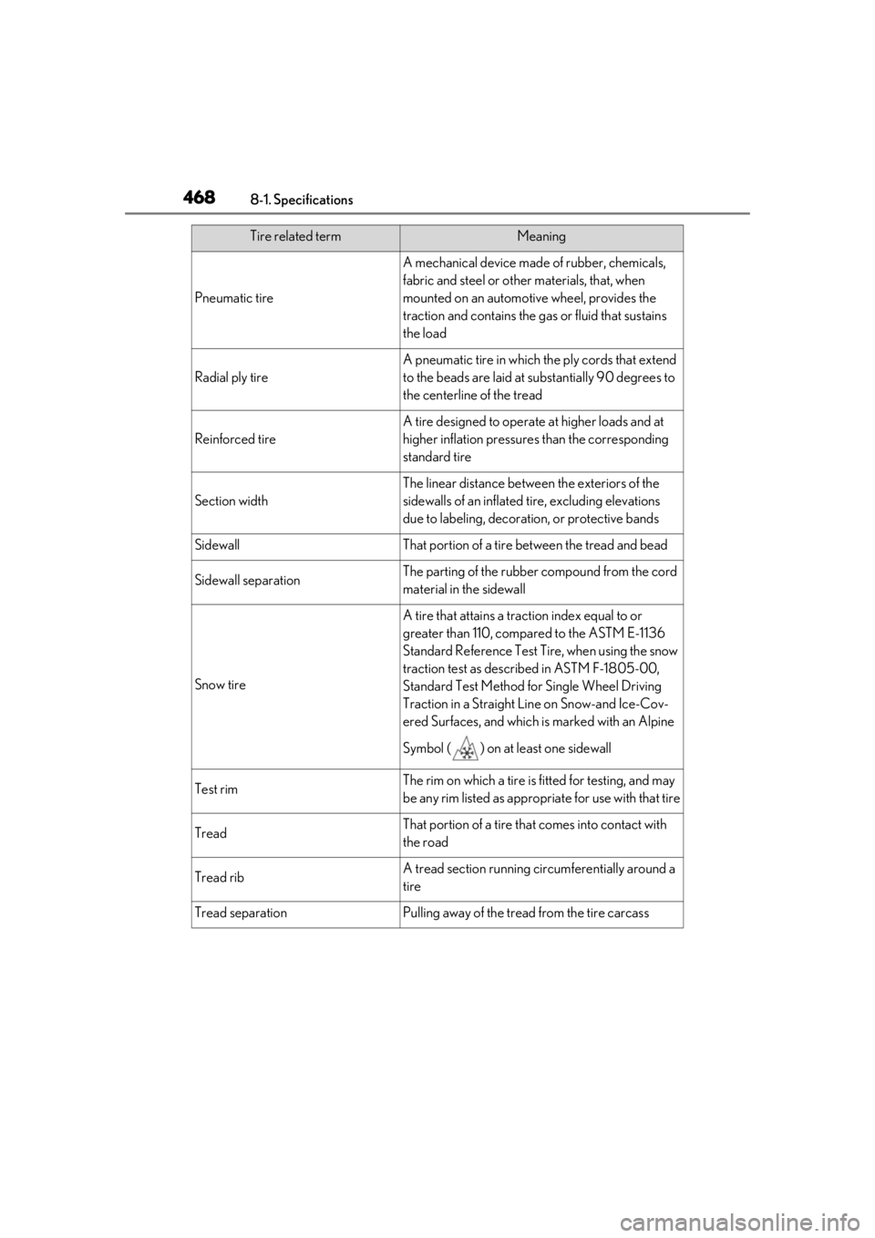
Snow tire
A tire that attains a traction index equal to or
greater than 110, compared to the ASTM E-1136
Standard Referenc e Test Tire, when using the snow
traction test as described in ASTM F-1805-00,
Standard Test Method fo r Single Wheel Driving
Traction in a Straight Line on Snow-and Ice-Cov-
ered Surfaces, and which is marked with an Alpine
Symbol ( ) on at least one sidewall
Test rimThe rim on which a tire is fitted for testing, and may
be any rim listed as appropriate for use with that tire
TreadThat portion of a tire that comes into contact with
the road
Tread ribA tread section running ci rcumferentially around a
tire
Tread separationPulling away of the tread from the tire carcass
Tire related termMeaning
Page 473 of 516
4718-2. Customization
8
Vehicle specifications
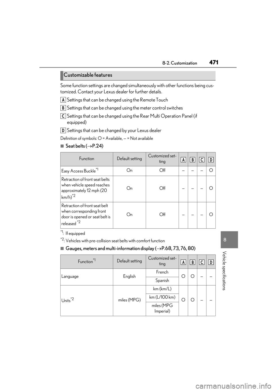
Some function settings are changed simultaneously with other functions being cus-
tomized. Contact your Lexus dealer for further details.
Settings that can be changed using the Remote Touch
Settings that can be changed using the meter control switches
Settings that can be changed using the Rear Multi Operation Panel (if
equipped)
Settings that can be changed by your Lexus dealer
Definition of symbols: O = Available, — = Not available
■Seat belts ( P.24)
*1: If equipped
*2: Vehicles with pre-collision se at belts with comfort function
■Gauges, meters and multi-information display ( P.68, 73, 76, 80)
Customizable features
FunctionDefault settingCustomized set-
ting
Easy Access Buckle*1OnOff———O
Retraction of front seat belts
when vehicle speed reaches
approximately 12 mph (20
km/h)
*2
OnOff———O
Retraction of front seat belt
when corresponding front
door is opened or seat belt is
released
*2
OnOff———O
Function*1Default settingCustomized set-ting
LanguageEnglishFrenchOO——Spanish
Units*2miles (MPG)
km (km/L)
OO——km (L/100 km)
miles (MPG Imperial)
A
B
C
D
ABCD
ABCD
Page 492 of 516
4909-1. For owners
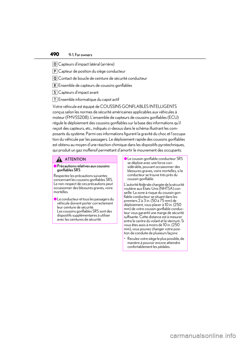
Capteurs d'impact latéral (arrière)
Capteur de position du siège conducteur
Contact de boucle de ceinture de sécurité conducteur
Ensemble de capteurs de coussins gonflables
Capteurs d'impact avant
Ensemble informatique du capot actif
Votre véhicule est équipé de CO USSINS GONFLABLES INTELLIGENTS
conçus selon les normes de sécurité américaines applicables aux véhicules à
moteur (FMVSS208). L'ensemble de cap teurs de coussins gonflables (ECU)
régule le déploiement des coussins gonflables sur la base des informations qu'il
reçoit des capteurs, etc., indiqués ci-dessus dans le schéma illustrant les com-
posants du système. Parmi ces informations figurent la gravité du choc et l'occupa-
tion du véhicule par les passagers. Le déploiement rapide des coussins gonflables
est obtenu au moyen d'une réaction chimique dans les dispositifs pyrotechniques,
qui produit un gaz inoffensif permettant d'amortir le mouvement des occupants.O
P
Q
R
S
T
ATTENTION
■Précautions relatives aux coussins
gonflables SRS
Respectez les précautions suivantes
concernant les coussins gonflables SRS.
Le non-respect de ces précautions peut
occasionner des blessures graves, voire
mortelles.
●Le conducteur et tous les passagers du
véhicule doivent porter correctement
leur ceinture de sécurité.
Les coussins gonflables SRS sont des
dispositifs supplémentaires à utiliser
avec les ceinture s de sécurité.
●Le coussin gonflable conducteur SRS
se déploie avec une force con-
sidérable, pouvant occasionner des
blessures graves, voire mortelles, si le
conducteur se trouve très près du
coussin gonflable.
L'autorité fédérale ch argée de la sécurité
routière aux États-Unis (NHTSA) con-
seille: La zone à risque du coussin gon-
flable conducteur se situant dans les
premiers 2 à 3 in. (50 à 75 mm) de
déploiement, vous placer à 10 in. (250
mm) de votre coussin gonflable conduc-
teur vous garantit une marge de sécurité
suffisante. Cette distance est à mesurer
entre le centre du vola nt et le sternum. Si
vous êtes assis à moins de 10 in. (250
mm), vous pouvez changer votre posi-
tion de conduite de plusieurs façons:
• Reculez votre siège le plus possible, de manière à pouvoir encore atteindre
confortablement les pédales.
Page 495 of 516
4939-1. For owners
9
For owners
ATTENTION
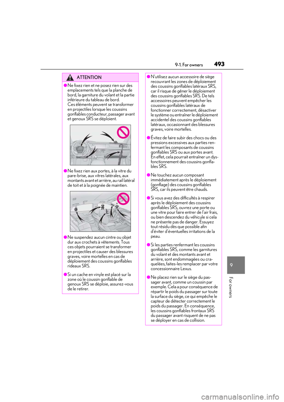
●Ne fixez rien et ne posez rien sur des
emplacements tels que la planche de
bord, la garniture du volant et la partie
inférieure du tableau de bord.
Ces éléments peuvent se transformer
en projectiles lorsque les coussins
gonflables conducteur, passager avant
et genoux SRS se déploient.
●Ne fixez rien aux portes, à la vitre du
pare-brise, aux vitres latérales, aux
montants avant et arrière, au rail latéral
de toit et à la poignée de maintien.
●Ne suspendez aucun cintre ou objet
dur aux crochets à vêtements. Tous
ces objets pourraient se transformer
en projectiles et causer des blessures
graves, voire mortelles en cas de
déploiement des coussins gonflables
rideaux SRS.
●Si un cache en vinyle est placé sur la
zone où le coussin gonflable de
genoux SRS se déploie, assurez-vous
de le retirer.
●N'utilisez aucun accessoire de siège
recouvrant les zones de déploiement
des coussins gonflables latéraux SRS,
car il risque de gêner le déploiement
des coussins gonflables SRS. De tels
accessoires peuvent empêcher les
coussins gonflables latéraux de
fonctionner correctement, désactiver
le système ou entraîner le déploiement
accidentel des coussins gonflables
latéraux, occasionna nt des blessures
graves, voire mortelles.
●Évitez de faire subir des chocs ou des
pressions excessives aux parties ren-
fermant les composants de coussins
gonflables SRS ou aux portes avant.
En effet, cela pourra it entraîner un dys-
fonctionnement des coussins gonfla-
bles SRS.
●Ne touchez aucun composant
immédiatement après le déploiement
(gonflage) des coussins gonflables
SRS, car ils peuvent être chauds.
●Si vous avez des di fficultés à respirer
après le déploiement des coussins
gonflables SRS, ouvrez une porte ou
une vitre pour faire entrer de l'air frais,
ou bien descendez du véhicule si cela
ne présente pas de danger. Essuyez
tout résidu dès que possible afin
d'éviter d'éventuelle s irritations de la
peau.
●Si les parties renfermant les coussins
gonflables SRS, comme les garnitures
du volant et des montants avant et
arrière, sont endommagées ou cra-
quelées, faites-les remplacer par votre
concessionnaire Lexus.
●Ne placez rien sur le siège du pas-
sager avant, comme un coussin par
exemple. Cela a pour conséquence de
répartir le poids du passager sur toute
la surface du siège, ce qui empêche le
capteur de détecter correctement le
poids du passager. En conséquence,
les coussins gonflables frontaux SRS
du passager avant risquent de ne pas
se déployer en cas de collision.