ECU LEXUS RC F 2016 Repair Manual
[x] Cancel search | Manufacturer: LEXUS, Model Year: 2016, Model line: RC F, Model: LEXUS RC F 2016Pages: 700, PDF Size: 14.12 MB
Page 453 of 700
4536-4. Using the other interior features
6
Interior features
RC350_RC300_RC200t_RC F_U (OM24671U)
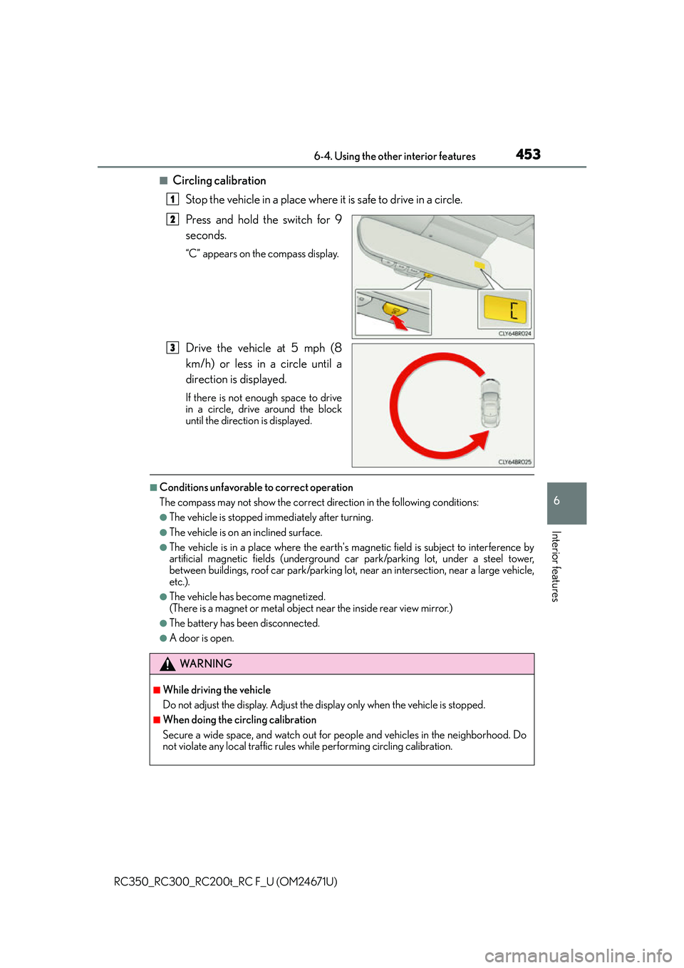
■Circling calibrationStop the vehicle in a place where it is safe to drive in a circle.
Press and hold the switch for 9
seconds.
“C” appears on the compass display.
Drive the vehicle at 5 mph (8
km/h) or less in a circle until a
direction is displayed.
If there is not enough space to drive
in a circle, drive around the block
until the direction is displayed.
■Conditions unfavorable to correct operation
The compass may not show the correct direction in the following conditions:
●The vehicle is stopped immediately after turning.
●The vehicle is on an inclined surface.
●The vehicle is in a place where the earth's ma gnetic field is subject to interference by
artificial magnetic fields (underground car park/parking lot, under a steel tower,
between buildings, roof car park/parking lot, near an intersection, near a large vehicle,
etc.).
●The vehicle has become magnetized.
(There is a magnet or metal object near the inside rear view mirror.)
●The battery has been disconnected.
●A door is open.
1
2
3
WA R N I N G
■While driving the vehicle
Do not adjust the display. Adjust the di splay only when the vehicle is stopped.
■When doing the circling calibration
Secure a wide space, and watch out for people and vehicles in the neighborhood. Do
not violate any local traffic rules while performing circling calibration.
Page 455 of 700

4556-4. Using the other interior features
6
Interior features
RC350_RC300_RC200t_RC F_U (OM24671U)
“SOS” button
LED light indicators
Microphone
LEXUS Enform Safety Connect
: If equipped
Safety Connect is a subscription-based telematics service that uses Global
Positioning System (GPS) data and embe dded cellular technology to provide
safety and security features to subscribers. Safety Connect is supported by
Lexus’ designated response center, wh ich operates 24 hours per day, 7 days
per week.
Safety Connect service is available by su bscription on select, telematics hard-
ware-equipped vehicles.
By using the Safety Connect service, yo u are agreeing to be bound by the
Telematics Subscription Service Agreement and its Terms and Conditions, as
in effect and amended from time to time, a current copy of which is available
at Lexus.com. All use of the Safety Connect service is subject to such then-
applicable Terms and Conditions.
System components
1
2
3
Page 476 of 700
4767-2. Maintenance
RC350_RC300_RC200t_RC F_U (OM24671U)
Vehicle interior
ItemsCheck points
Accelerator pedal• The accelerator pedal should move smoothly (with- out uneven pedal effort or catching).
Automatic transmission
“Park” mechanism• When parked on a slope and the shift lever is in P, isthe vehicle securely stopped?
Brake pedal
• Does the brake pedal move smoothly?
• Does the brake pedal have appropriate clearance
from the floor? ( P. 6 2 9 )
• Does the brake pedal have the correct amount of
free play? ( P. 6 2 9 )
Brakes
• The vehicle should not pull to one side when the
brakes are applied.
• The brakes should work effectively.
• The brake pedal should not feel spongy.
• The brake pedal should not get too close to the floor when the brakes are applied.
Head restraints
(RC350/RC300/
RC200t)• Do the head restraints move smoothly and locksecurely?
Indicators/buzzers• Do the indicators and buzzers function properly?
Lights• Do all the lights come on?
Parking brake• Does the parking brake pedal move smoothly?
• When parked on a slope and the parking brake is on,
is the vehicle securely stopped?
Seat belts•Do the seat belt s operate smoothly?
• The seat belts should not be damaged.
Seats• Do the seat controls operate properly?
Steering wheel
• Does the steering wheel rotate smoothly?
• Does the steering wheel have the correct amount of free play?
• There should not be an y strange sounds coming
from the steering wheel.
Page 530 of 700

5307-3. Do-it-yourself maintenance
RC350_RC300_RC200t_RC F_U (OM24671U)
WA R N I N G
■Replacing light bulbs
●Turn off the lights. Do not attempt to replace the bulb immediately after turning off the
lights.
The bulbs become very hot and may cause burns.
●Do not touch the glass portion of the light bulb with bare hands. When it is unavoid-
able to hold the glass portion, use and ho ld with a clean dry cloth to avoid getting
moisture and oils on the bulb.
Also, if the bulb is scratched or dropped, it may blow out or crack.
●Fully install light bulbs and any parts used to secure them. Failure to do so may result
in heat damage, fire, or water entering the headlight unit. This may damage the head-
lights or cause condensation to build up on the lens.
■To prevent damage or fire
●Make sure bulbs are fully seated and locked.
●Check the wattage of the bulb before installin g to prevent heat damage.
Page 533 of 700
5338-1. Essential information
8
When trouble arises
RC350_RC300_RC200t_RC F_U (OM24671U)
Steadily step on the brake pedal with both feet and firmly depress it.
Do not pump the brake pedal repeatedly as this will increase the effort required to
slow the vehicle.
Shift the shift lever to N.
If the shift lever is shifted to N
After slowing down, stop the vehicle in a safe place by the road.
Stop the engine.
If the shift lever cannot be shifted to N
Keep depressing the brake pedal with both feet to reduce vehicle speed as
much as possible.
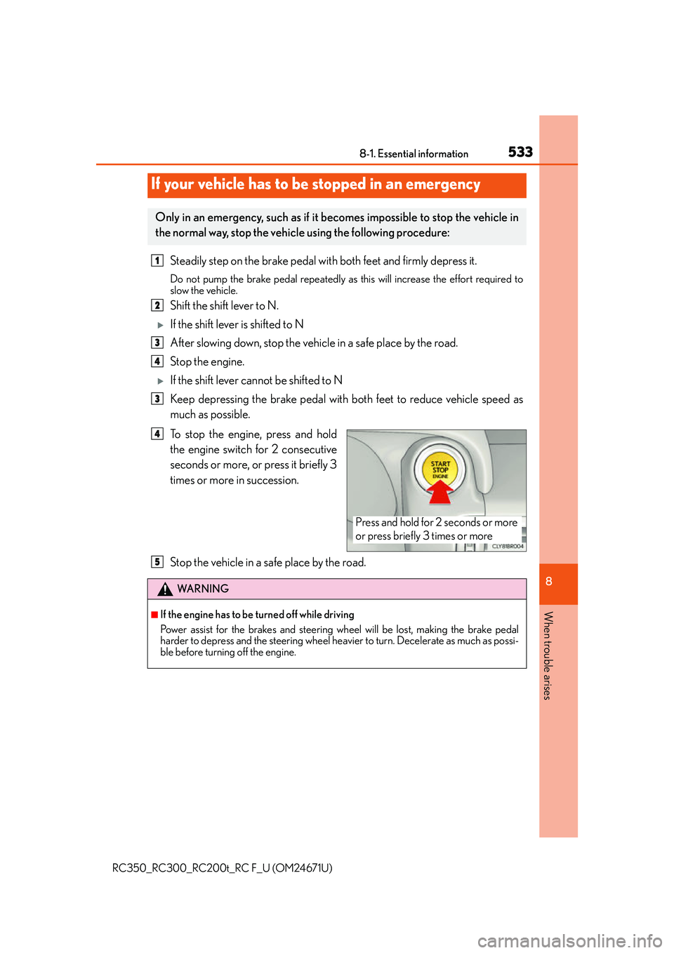
To stop the engine, press and hold
the engine switch for 2 consecutive
seconds or more, or press it briefly 3
times or more in succession.
Stop the vehicle in a safe place by the road.
If your vehicle has to be stopped in an emergency
Only in an emergency, such as if it becomes impossible to stop the vehicle in
the normal way, stop the vehicle using the following procedure:
1
2
3
4
3
Press and hold for 2 seconds or more
or press briefly 3 times or more
4
WA R N I N G
■If the engine has to be turned off while driving
Power assist for the brakes and steering wheel will be lost, making the brake pedal
harder to depress and the steering wheel heavier to turn. Decelerate as much as possi-
ble before turning off the engine.
5
Page 536 of 700
5368-2. Steps to take in an emergency
RC350_RC300_RC200t_RC F_U (OM24671U)
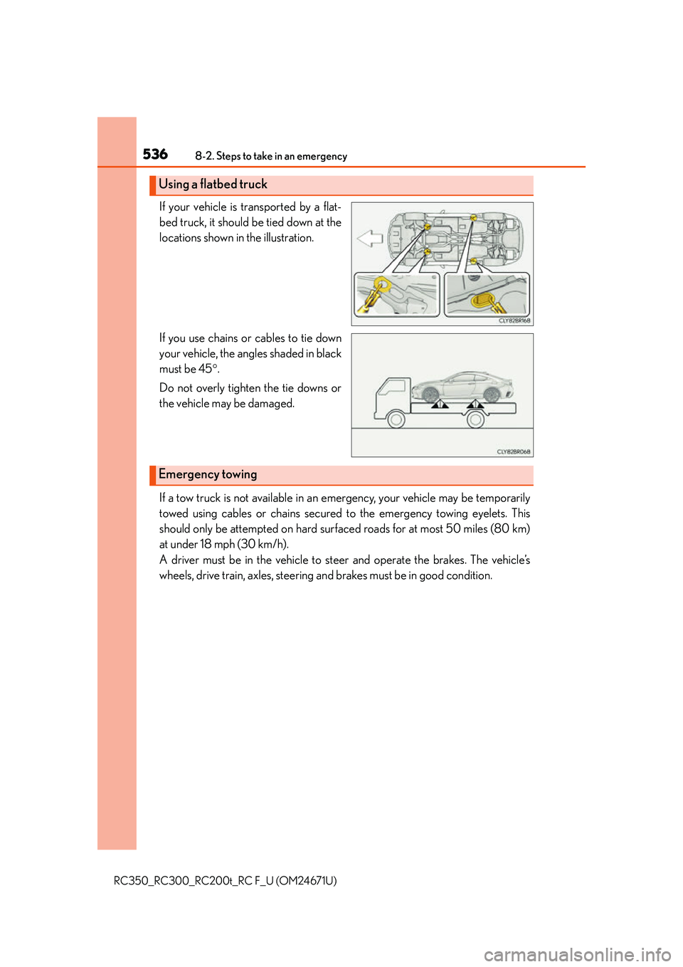
If your vehicle is transported by a flat-
bed truck, it should be tied down at the
locations shown in the illustration.
If you use chains or cables to tie down
your vehicle, the angles shaded in black
must be 45.
Do not overly tighten the tie downs or
the vehicle may be damaged.
If a tow truck is not available in an emergency, your vehicle may be temporarily
towed using cables or chains secured to the emergency towing eyelets. This
should only be attempted on hard surf aced roads for at most 50 miles (80 km)
at under 18 mph (30 km/h).
A driver must be in the vehicle to steer and operate the brakes. The vehicle’s
wheels, drive train, axles, steering an d brakes must be in good condition.
Using a flatbed truck
Emergency towing
Page 538 of 700

5388-2. Steps to take in an emergency
RC350_RC300_RC200t_RC F_U (OM24671U)
Insert the towing eyelet into the hole
and tighten partially by hand.
Tighten down the towing eyelet
securely using a wheel nut wrench
or hard metal bar.
Securely attach cables or chains to the towing eyelet.
Take care not to damage the vehicle body.
Enter the vehicle being towed and start the engine.
If the engine does not start, turn the engine switch to IGNITION ON mode.
Shift the shift lever to N and release the parking brake.
When the shift lever cannot be shifted: P. 5 9 9
■While towing
If the engine is not running, the power assist for the brakes and steering will not function,
making steering and br aking more difficult.
■Wheel nut wrench
Wheel nut wrench is installed in trunk. ( P. 571, 585)
3
4
5
6
7
Page 540 of 700
5408-2. Steps to take in an emergency
RC350_RC300_RC200t_RC F_U (OM24671U)
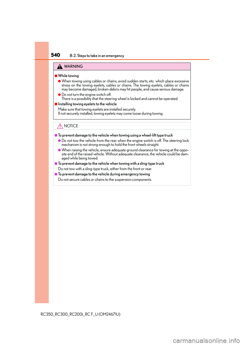
WA R N I N G
■While towing
●When towing using cables or chains, avoid sudden starts, etc. which place excessive
stress on the towing eyelets, cables or chains. The towing eyelets, cables or chains
may become damaged, broken debris may hit people, and cause serious damage.
●Do not turn the engine switch off.
There is a possibility that the steering wheel is locked and cannot be operated.
■Installing towing eyelets to the vehicle
Make sure that towing eyelets are installed securely.
If not securely installed, towing eyelets may come loose during towing.
NOTICE
■To prevent damage to the vehicle when towing using a wheel-lift type truck
●Do not tow the vehicle from the rear when the engine switch is off. The steering lock
mechanism is not strong enough to hold the front wheels straight.
●When raising the vehicle, ensure adequate ground clearance for towing at the oppo-
site end of the raised vehicle. Without adequate clearance, the vehicle could be dam-
aged while being towed.
■To prevent damage to the vehicle when towing with a sling-type truck
Do not tow with a sling-type truck, either from the front or rear.
■To prevent damage to the vehicle during emergency towing
Do not secure cables or chains to the suspension components.
Page 546 of 700
5468-2. Steps to take in an emergency
RC350_RC300_RC200t_RC F_U (OM24671U)
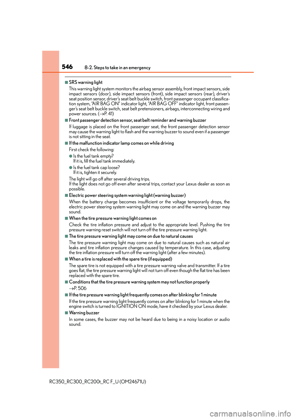
■SRS warning light
This warning light system monitors the airbag sensor assembly, front impact sensors, side
impact sensors (door), side impact sensors (f ront), side impact sensors (rear), driver’s
seat position sensor, driver’s seat belt buck le switch, front passenger occupant classifica-
tion system, “AIR BAG ON” indicator light, “A IR BAG OFF” indicator light, front passen-
ger’s seat belt buckle switch, seat belt pretensioners, airbags, interconnecting wiring and
power sources. ( P. 41)
■Front passenger detection sensor, seat belt reminder and warning buzzer
If luggage is placed on the front passenger seat, the front passenger detection sensor
may cause the warning light to flash and the wa rning buzzer to sound even if a passenger
is not sitting in the seat.
■If the malfunction indicator lamp comes on while driving
First check the following:
●Is the fuel tank empty?
If it is, fill the fuel tank immediately.
●Is the fuel tank cap loose?
If it is, tighten it securely.
The light will go off after several driving trips.
If the light does not go off even after severa l trips, contact your Lexus dealer as soon as
possible.
■Electric power steering system warning light (warning buzzer)
When the battery charge becomes insufficie nt or the voltage temporarily drops, the
electric power steering system warning light may come on and the warning buzzer may
sound.
■When the tire pressure warning light comes on
Check the tire inflation pressure and adjust to the appropriate level. Pushing the tire
pressure warning reset switch will not tu rn off the tire pressure warning light.
■The tire pressure warning light may come on due to natural causes
The tire pressure warning light may come on due to natural causes such as natural air
leaks and tire inflation pressure changes caused by temperature. In this case, adjusting
the tire inflation pressure will turn off the warning light (after a few minutes).
■When a tire is replaced with the spare tire (if equipped)
The spare tire is not equipped with a tire pr essure warning valve and transmitter. If a tire
goes flat, the tire pressure warning light will no t turn off even though the flat tire has been
replaced with the spare tire.
■Conditions that the tire pressure warning system may not function properly
P. 5 0 6
■If the tire pressure warning light frequently comes on after blinking for 1 minute
If the tire pressure warning light frequently comes on after blinking for 1 minute when the
engine switch is turned to IGNITION ON mo de, have it checked by your Lexus dealer.
■Warning buzzer
In some cases, the buzzer may not be heard due to being in a noisy location or audio
sound.
Page 568 of 700

5688-2. Steps to take in an emergency
RC350_RC300_RC200t_RC F_U (OM24671U)
Once
• When the doors were unlockedwith the mechanical key and then
the engine switch was pressed,
the electronic key could not be
detected in the vehicle.
• The electronic key could not be detected in the vehicle even after
the engine switch was pressed
two consecutive times.
Touch the electronic key to the
engine switch while depressing
the brake pedal.
Once
During an engine starting proce-
dure in the event that the electronic
key was not functioning properly
( P. 602), the engine switch was
touched with the electronic key.
Press the engine switch within
10 seconds of the buzzer sound-
ing.
Indicates that:
• With the engine switch off, the
doors were unlocked and then the
driver's door was opened and
closed
• The engine switch was turned to ACCESSORY mode without
starting the engine
• The shift lever was shifted to P or N from another shift position with
the engine switch in IGNITION
ON mode.
Press the engine switch while
depressing the brake pedal.
The engine switch has been turned
off with the shift lever in a position
other than P or N.
Shift the shift lever to P.
Interior
buzzerExteriorbuzzerWa r n i n g m e s s a g eDetails/Actions
(Flashes)
(Flashes)