turn signal LEXUS RC300 2021 User Guide
[x] Cancel search | Manufacturer: LEXUS, Model Year: 2021, Model line: RC300, Model: LEXUS RC300 2021Pages: 400, PDF Size: 7.9 MB
Page 172 of 400
1724-5. Using the driving support systems
Lane departure alert function is operating.
Operation display of steering
wheel operation support
Indicates that steering wheel assistance of
the steering control function is operating.
Lane departure alert function dis-
play
Displayed when the mu lti-information dis-
play is switched to the driving assist system
information screen.
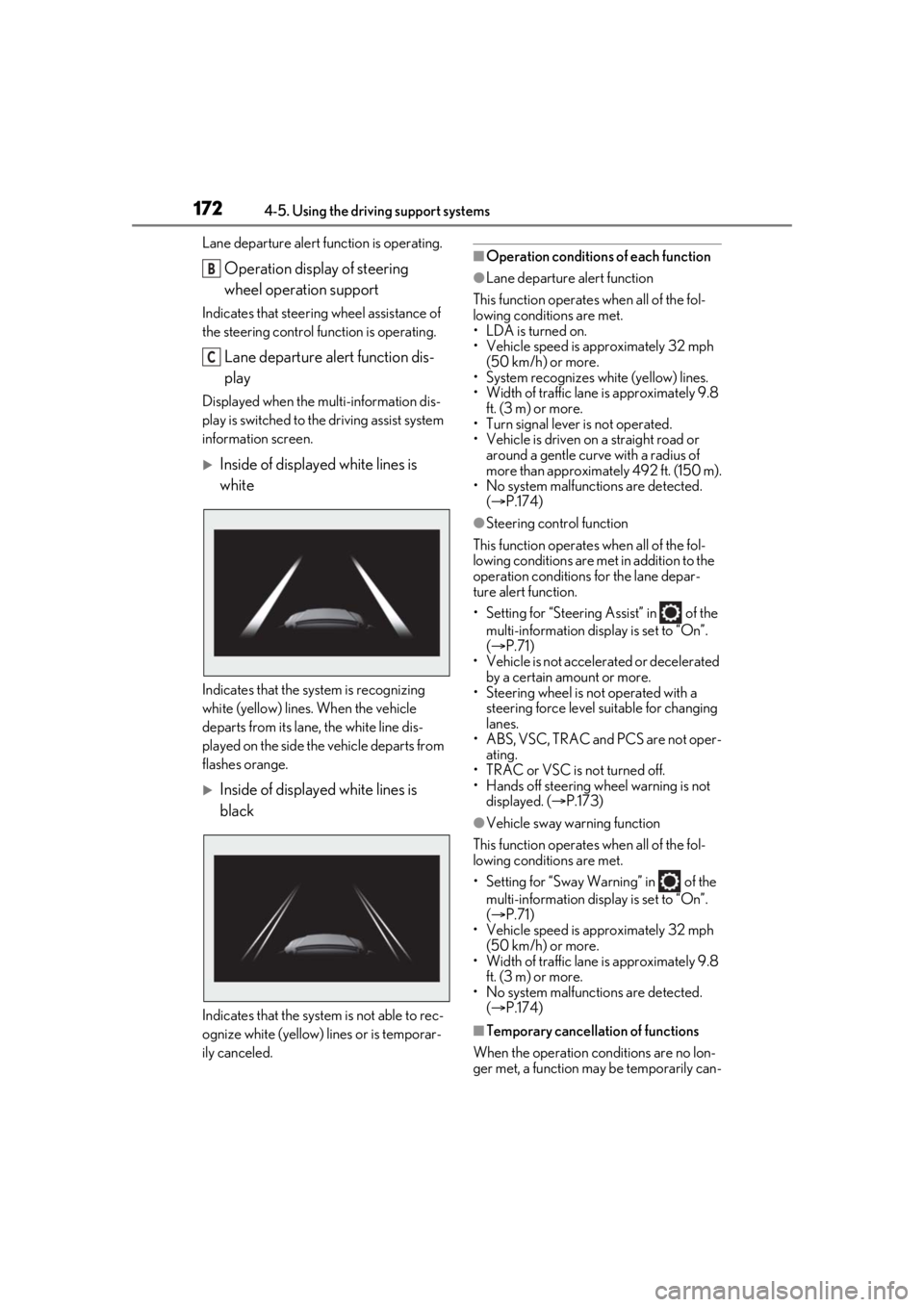
Inside of displayed white lines is
white
Indicates that the system is recognizing
white (yellow) lines. When the vehicle
departs from its lane , the white line dis-
played on the side the vehicle departs from
flashes orange.
Inside of displayed white lines is
black
Indicates that the system is not able to rec-
ognize white (yellow) lines or is temporar-
ily canceled.
■Operation conditions of each function
●Lane departure alert function
This function operates when all of the fol-
lowing conditions are met.
• LDA is turned on.
• Vehicle speed is approximately 32 mph (50 km/h) or more.
• System recognizes white (yellow) lines.
• Width of traffic lane is approximately 9.8 ft. (3 m) or more.
• Turn signal lever is not operated.
• Vehicle is driven on a straight road or around a gentle curve with a radius of
more than approximately 492 ft. (150 m).
• No system malfunctions are detected.
( P.174)
●Steering control function
This function operates when all of the fol-
lowing conditions are met in addition to the
operation conditions for the lane depar-
ture alert function.
• Setting for “Steering Assist” in of the multi-information display is set to “On”.
( P.71)
• Vehicle is not acceler ated or decelerated
by a certain amount or more.
• Steering wheel is not operated with a steering force level su itable for changing
lanes.
• ABS, VSC, TRAC and PCS are not oper- ating.
• TRAC or VSC is not turned off.
• Hands off steering wheel warning is not displayed. ( P.173)
●Vehicle sway warning function
This function operates when all of the fol-
lowing conditions are met.
• Setting for “Sway Warning” in of the multi-information display is set to “On”.
( P.71)
• Vehicle speed is approximately 32 mph
(50 km/h) or more.
• Width of traffic lane is approximately 9.8 ft. (3 m) or more.
• No system malfunctions are detected. ( P.174)
■Temporary cancellation of functions
When the operation conditions are no lon-
ger met, a function may be temporarily can-
B
C
Page 191 of 400
1914-5. Using the driving support systems
4
Driving
*:If equipped
The Blind Spot Monitor is a system that
has 2 functions:
The BSM (Blind Spot Monitor) func-
tion
Assists the driver in making a deci-
sion when changing lanes
The RCTA (Rear Cross Traffic Alert)
function
Assists the driver when backing up
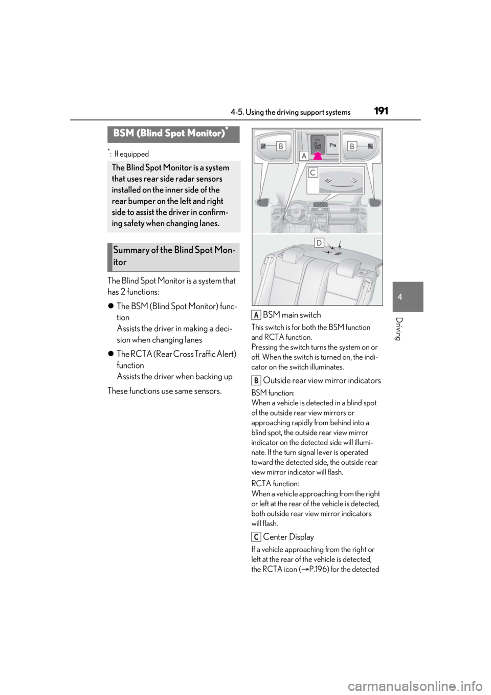
These functions use same sensors. BSM main switch
This switch is for both the BSM function
and RCTA function.
Pressing the switch turns the system on or
off. When the switch is turned on, the indi-
cator on the switch illuminates.
Outside rear view mirror indicators
BSM function:
When a vehicle is dete
cted in a blind spot
of the outside rear view mirrors or
approaching rapidly from behind into a
blind spot, the outside rear view mirror
indicator on the detected side will illumi-
nate. If the turn signal lever is operated
toward the detected side, the outside rear
view mirror indicator will flash.
RCTA function:
When a vehicle approaching from the right
or left at the rear of the vehicle is detected,
both outside rear view mirror indicators
will flash.
Center Display
If a vehicle approaching from the right or
left at the rear of th e vehicle is detected,
the RCTA icon ( P.196) for the detected
BSM (Blind Spot Monitor)*
The Blind Spot Monitor is a system
that uses rear side radar sensors
installed on the inner side of the
rear bumper on the left and right
side to assist the driver in confirm-
ing safety when changing lanes.
Summary of the Blind Spot Mon-
itor
A
B
C
Page 268 of 400
2686-3. Do-it-yourself maintenance
information will not be updated.
If this accidentally occurs, either turn the
engine switch to off and then to IGNITION
ON mode, or initialize the system after
checking that the tire pressure is properly
adjusted.
Your vehicle is equipped with a tire
pressure warning system that uses tire
pressure warning valves and transmit-
ters to detect low tire inflation pressure
before serious problems arise.
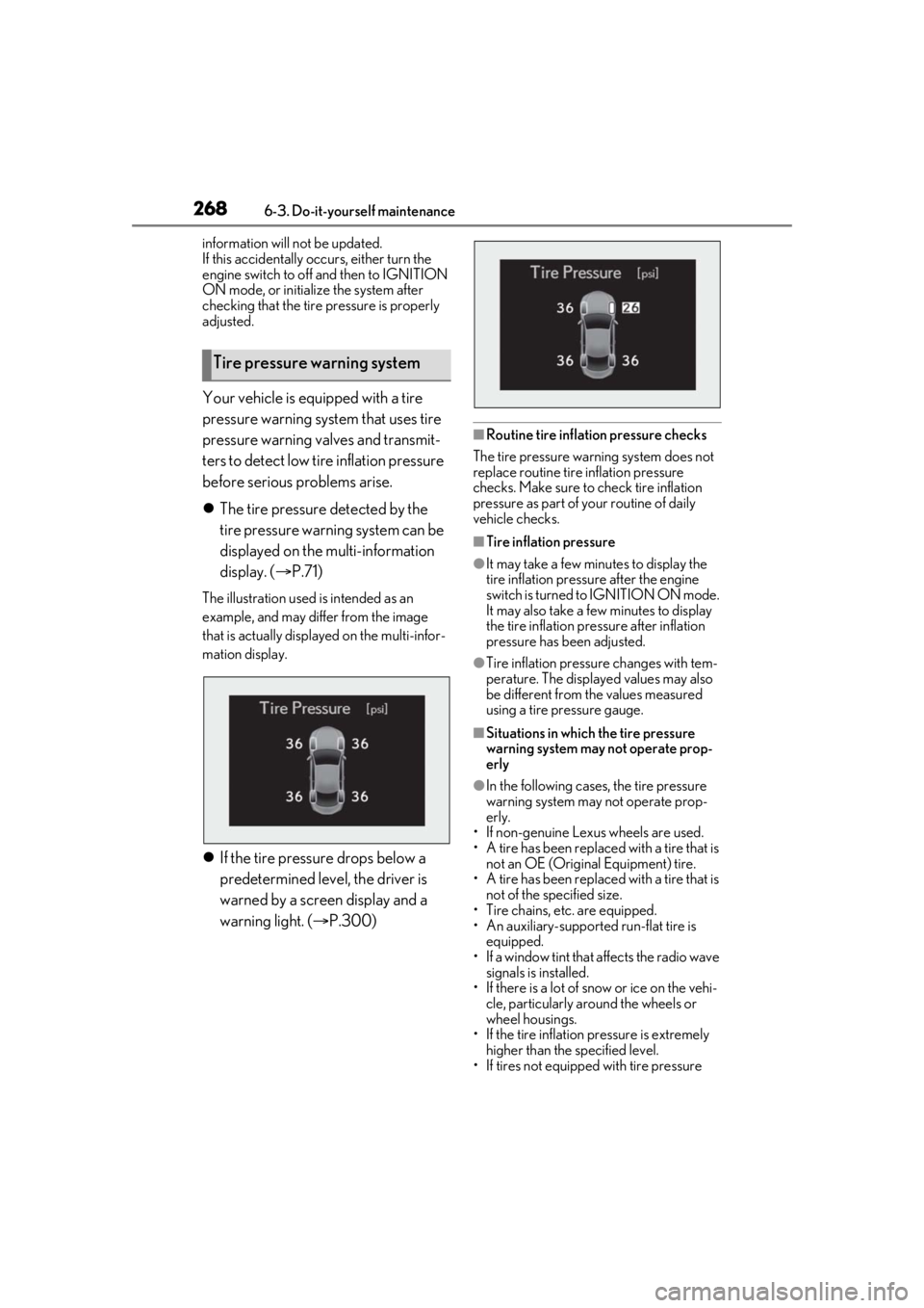
The tire pressure detected by the
tire pressure warning system can be
displayed on the multi-information
display. ( P.71)
The illustration used is intended as an
example, and may differ from the image
that is actually displayed on the multi-infor-
mation display.
If the tire pressure drops below a
predetermined level, the driver is
warned by a screen display and a
warning light. ( P.300)
■Routine tire inflation pressure checks
The tire pressure warning system does not
replace routine tire inflation pressure
checks. Make sure to check tire inflation
pressure as part of your routine of daily
vehicle checks.
■Tire inflation pressure
●It may take a few minutes to display the
tire inflation pressu re after the engine
switch is turned to IGNITION ON mode.
It may also take a few minutes to display
the tire inflation pressure after inflation
pressure has b een adjusted.
●Tire inflation pressure changes with tem-
perature. The displaye d values may also
be different from the values measured
using a tire pressure gauge.
■Situations in which the tire pressure
warning system may not operate prop-
erly
●In the following cases, the tire pressure
warning system may not operate prop-
erly.
• If non-genuine Lexus wheels are used.
• A tire has been replaced with a tire that is
not an OE (Original Equipment) tire.
• A tire has been replaced with a tire that is
not of the specified size.
• Tire chains, etc. are equipped.
• An auxiliary-supported run-flat tire is equipped.
• If a window tint that affects the radio wave signals is installed.
• If there is a lot of snow or ice on the vehi-
cle, particularly around the wheels or
wheel housings.
• If the tire inflation pressure is extremely
higher than the specified level.
• If tires not equipped with tire pressure
Tire pressure warning system
Page 281 of 400
2816-3. Do-it-yourself maintenance
6
Maintenance and care
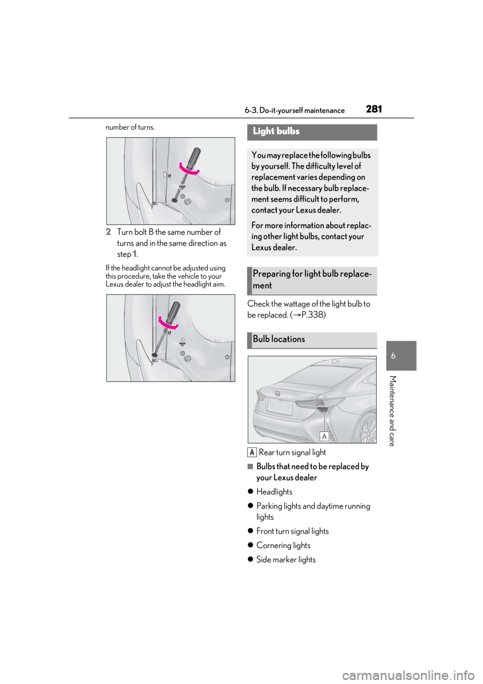
number of turns.
2Turn bolt B the same number of
turns and in the same direction as
step 1.
If the headlight cannot be adjusted using
this procedure, take the vehicle to your
Lexus dealer to adjust the headlight aim.
Check the wattage of the light bulb to
be replaced. ( P.338)
Rear turn signal light
■Bulbs that need to be replaced by
your Lexus dealer
Headlights
Parking lights and daytime running
lights
Front turn signal lights
Cornering lights
Side marker lights
Light bulbs
You may replace the following bulbs
by yourself. The difficulty level of
replacement varies depending on
the bulb. If necessary bulb replace-
ment seems difficult to perform,
contact your Lexus dealer.
For more information about replac-
ing other light bulbs, contact your
Lexus dealer.
Preparing for light bulb replace-
ment
Bulb locations
A
Page 282 of 400
2826-3. Do-it-yourself maintenance
Side turn signal lights
Stop/tail lights
Back-up light
High mounted stoplight
License plate lights
■LED light bulbs
The lights other than the rear turn signal
lights each consist of a number of LEDs. If
any of the LEDs burn out, take your vehicle
to your Lexus dealer to have the light
replaced.
■Condensation build-up on the inside of
the lens
Temporary condensation build-up on the
inside of the headlight lens does not indi-
cate a malfunction. Contact your Lexus
dealer for more information in the following
situations:
●Large drops of water ha ve built up on the
inside of the lens.
●Water has built up inside the headlight.
■When replacing light bulbs
P.280
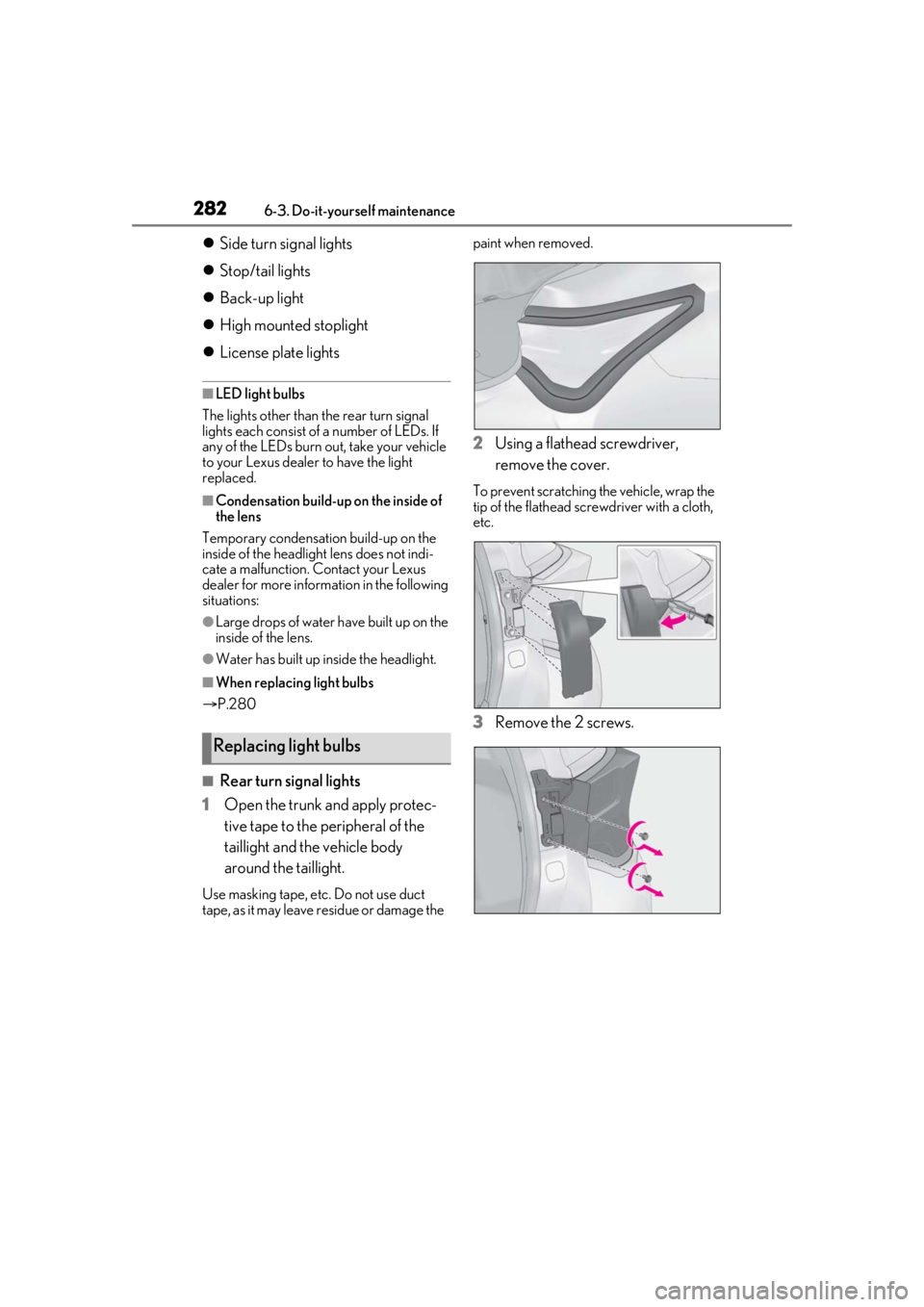
■Rear turn signal lights
1 Open the trunk and apply protec-
tive tape to the peripheral of the
taillight and the vehicle body
around the taillight.
Use masking tape, etc. Do not use duct
tape, as it may leave residue or damage the paint when removed.
2
Using a flathead screwdriver,
remove the cover.
To prevent scratching the vehicle, wrap the
tip of the flathead scre wdriver with a cloth,
etc.
3 Remove the 2 screws.
Replacing light bulbs
Page 283 of 400
2836-3. Do-it-yourself maintenance
6
Maintenance and care
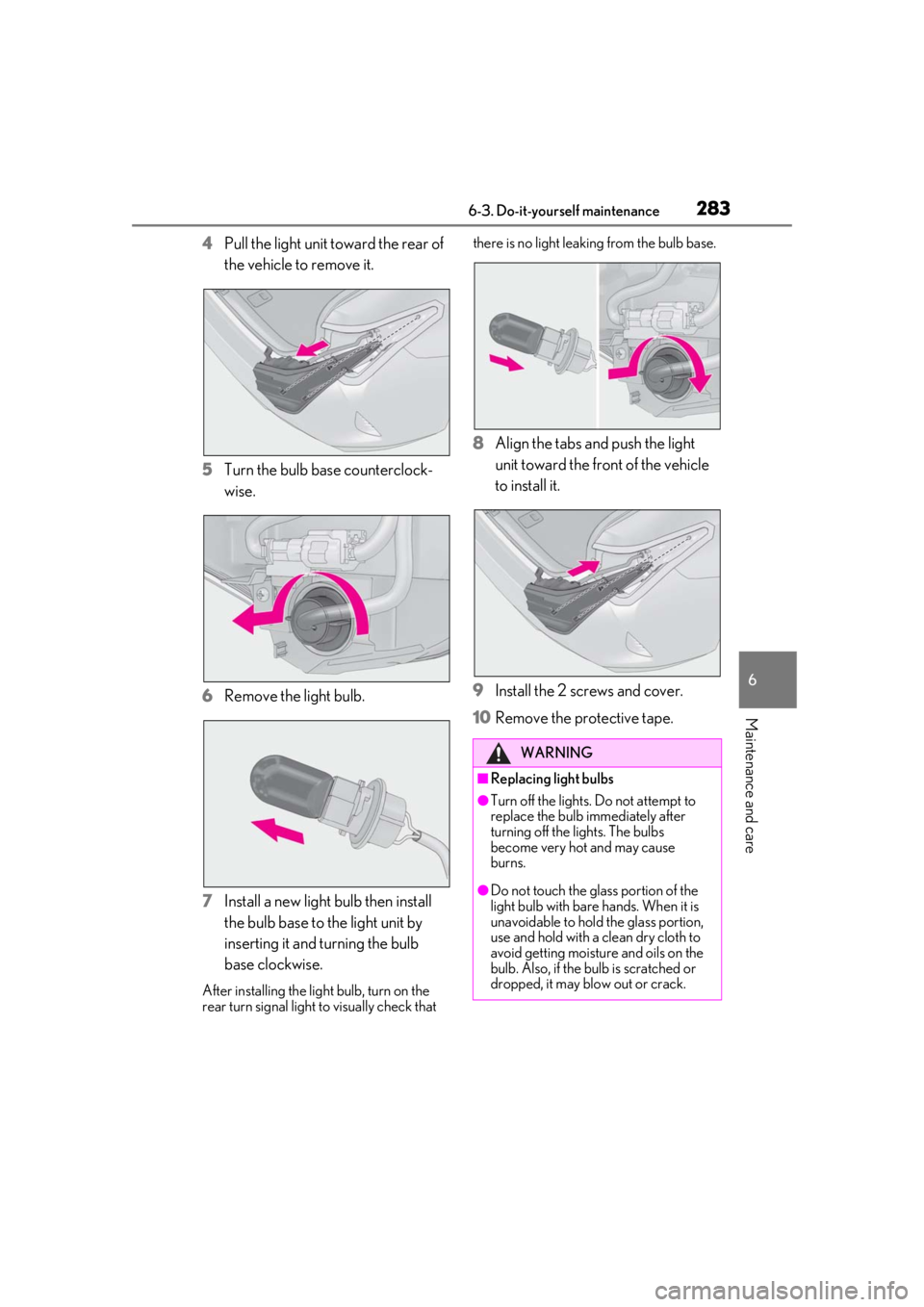
4Pull the light unit toward the rear of
the vehicle to remove it.
5 Turn the bulb base counterclock-
wise.
6 Remove the light bulb.
7 Install a new light bulb then install
the bulb base to the light unit by
inserting it and turning the bulb
base clockwise.
After installing the light bulb, turn on the
rear turn signal light to visually check that there is no light leaking from the bulb base.
8
Align the tabs and push the light
unit toward the front of the vehicle
to install it.
9 Install the 2 screws and cover.
10 Remove the protective tape.
WARNING
■Replacing light bulbs
●Turn off the lights. Do not attempt to
replace the bulb immediately after
turning off the lights. The bulbs
become very hot and may cause
burns.
●Do not touch the glass portion of the
light bulb with bare hands. When it is
unavoidable to hold the glass portion,
use and hold with a clean dry cloth to
avoid getting moisture and oils on the
bulb. Also, if the bu lb is scratched or
dropped, it may blow out or crack.
Page 286 of 400
2867-1. Essential information
7-1.Essential information
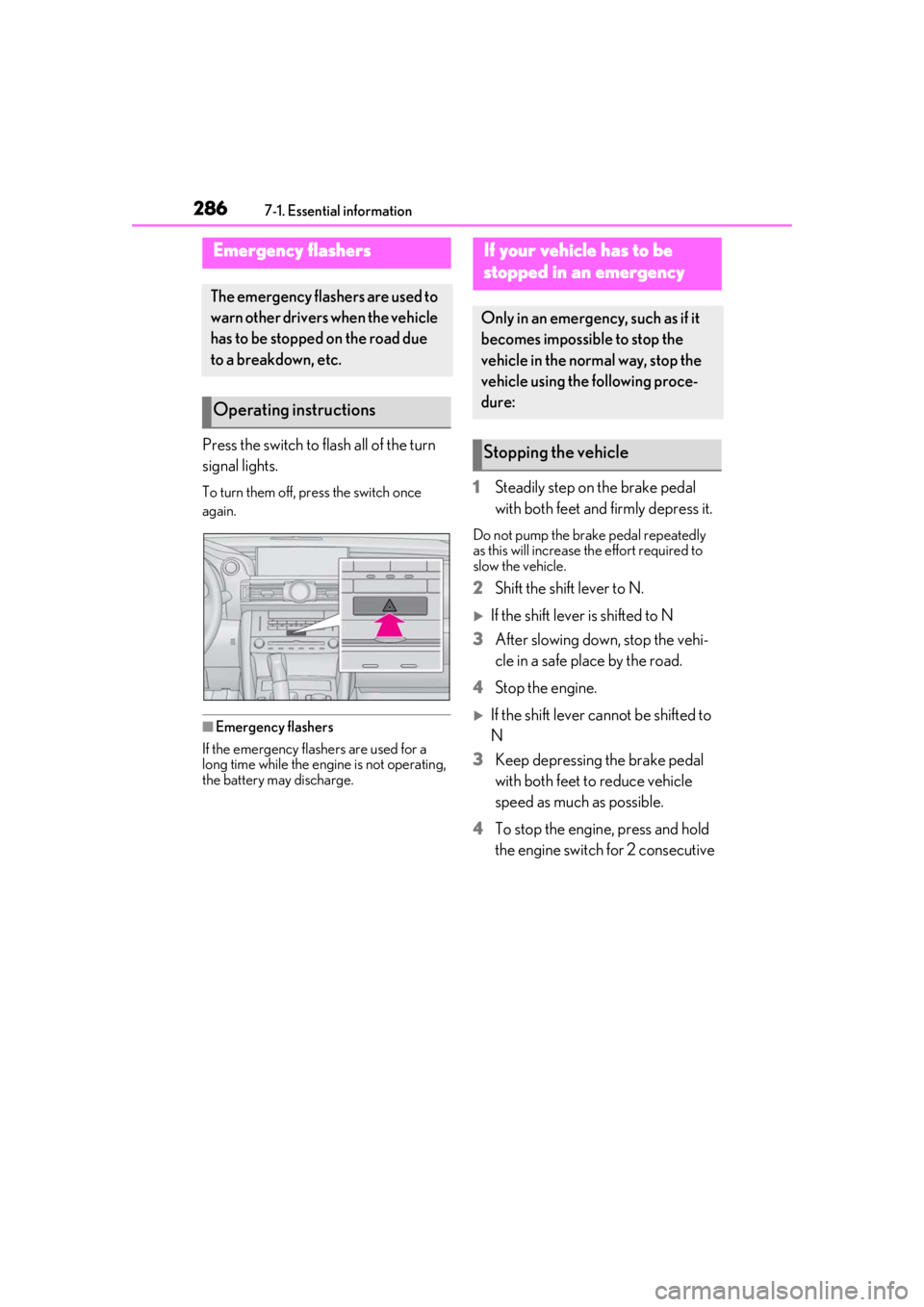
Press the switch to flash all of the turn
signal lights.
To turn them off, press the switch once
again.
■Emergency flashers
If the emergency flashers are used for a
long time while the engine is not operating,
the battery may discharge.
1 Steadily step on the brake pedal
with both feet and firmly depress it.
Do not pump the brake pedal repeatedly
as this will increase the effort required to
slow the vehicle.
2Shift the shift lever to N.
If the shift lever is shifted to N
3 After slowing down, stop the vehi-
cle in a safe place by the road.
4 Stop the engine.
If the shift lever cannot be shifted to
N
3 Keep depressing the brake pedal
with both feet to reduce vehicle
speed as much as possible.
4 To stop the engine, press and hold
the engine switch for 2 consecutive
Emergency flashers
The emergency flashers are used to
warn other drivers when the vehicle
has to be stopped on the road due
to a breakdown, etc.
Operating instructions
If your vehicle has to be
stopped in an emergency
Only in an emergency, such as if it
becomes impossible to stop the
vehicle in the normal way, stop the
vehicle using the following proce-
dure:
Stopping the vehicle
Page 338 of 400
3388-1. Specifications
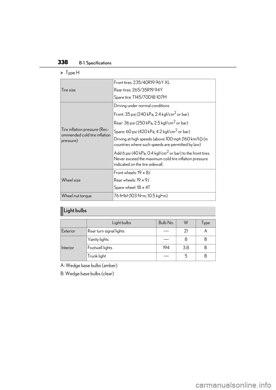
Type H
A: Wedge base bulbs (amber)
B: Wedge base bulbs (clear)
Tire size
Front tires: 235/40R19 96Y XL
Rear tires: 265/35R19 94Y
Spare tire: T145/70D18 107M
Tire inflation pressure (Rec-
ommended cold tire inflation
pressure)
Driving under normal conditions
Front: 35 psi (240 kPa, 2.4 kgf/cm
2 or bar)
Rear: 36 psi (250 kPa, 2.5 kgf/cm
2 or bar)
Spare: 60 psi (420 kPa, 4.2 kgf/cm
2 or bar)
Driving at high speeds (above 100 mph [160 km/h]) (in
countries where such speeds are permitted by law)
Add 6 psi (40 kPa, 0.4 kgf/cm
2 or bar) to the front tires.
Never exceed the maximum cold tire inflation pressure
indicated on the tire sidewall.
Wheel size
Front wheels: 19 8J
Rear wheels: 19 9J
Spare wheel: 18 4T
Wheel nut torque76 ft•lbf (103 N•m, 10.5 kgf•m)
Light bulbs
Light bulbsBulb No.WType
ExteriorRear turn signal lights21A
Interior
Vanity lights8B
Footwell lights1943.8B
Trunk light5B
Page 356 of 400
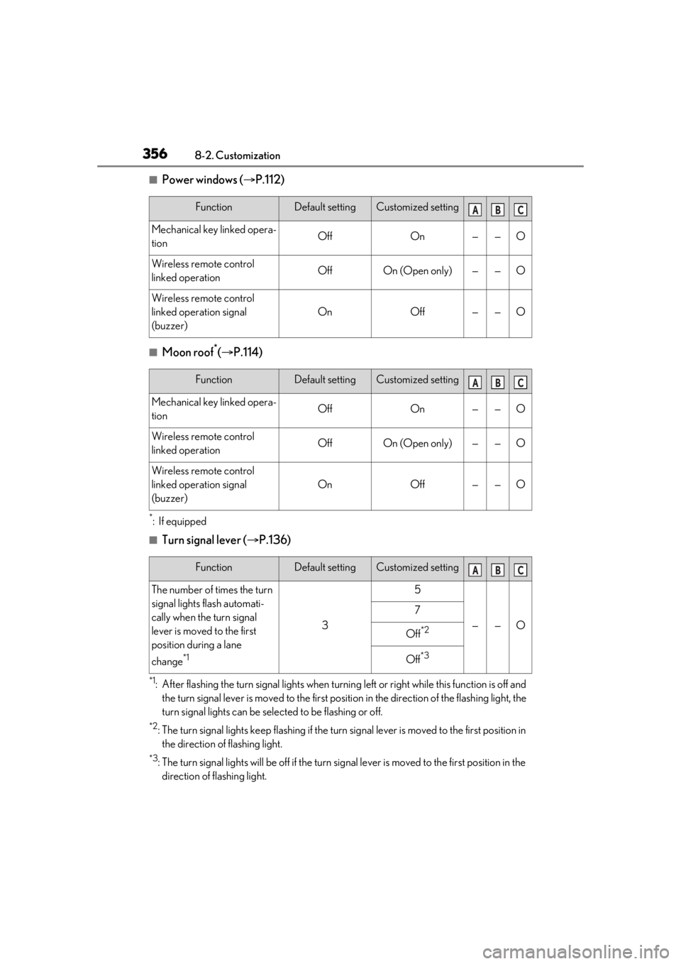
3568-2. Customization
■Power windows (P.112)
■Moon roof*( P.114)
*:If equipped
■Turn signal lever ( P.136)
*1: After flashing the turn signal lights when turnin g left or right while this function is off and
the turn signal lever is moved to the first positi on in the direction of the flashing light, the
turn signal lights can be sele cted to be flashing or off.
*2: The turn signal lights keep flashing if the turn signal lever is moved to the first position in
the direction of flashing light.
*3: The turn signal lights will be off if the turn si gnal lever is moved to the first position in the
direction of flashing light.
FunctionDefault settingCustomized setting
Mechanical key linked opera-
tionOffOn——O
Wireless remote control
linked operationOffOn (Open only)——O
Wireless remote control
linked operation signal
(buzzer)
OnOff——O
ABC
FunctionDefault settingCustomized setting
Mechanical key linked opera-
tionOffOn——O
Wireless remote control
linked operationOffOn (Open only)——O
Wireless remote control
linked operation signal
(buzzer)
OnOff——O
ABC
FunctionDefault settingCustomized setting
The number of times the turn
signal lights flash automati-
cally when the turn signal
lever is moved to the first
position during a lane
change
*1
3
5
——O
7
Off*2
Off*3
ABC
Page 360 of 400

3608-2. Customization
function cannot be customized.
●When the doors remain closed after
unlocking the doors and the timer acti-
vated automatic door lock function acti-
vates, signals will be generated in
accordance with the operation buzzer
volume and operational signal (Emer-
gency flashers) function settings.
●Some settings can be changed using a
switch or the Center Display. If a setting is
changed using a switch, the changed set-
ting will not be reflected on the Center
Display screen until the engine switch is
turned off and then to IGNITION ON
mode.