LEXUS RCF 2019 Owners Manual
Manufacturer: LEXUS, Model Year: 2019, Model line: RCF, Model: LEXUS RCF 2019Pages: 636, PDF Size: 12.48 MB
Page 481 of 636
4817-2. Steps to take in an emergency
RC F_U 7
When trouble arises
* : Refer to the separate “Scheduled Mainte nance” or “Owner’s Manual Supplement”
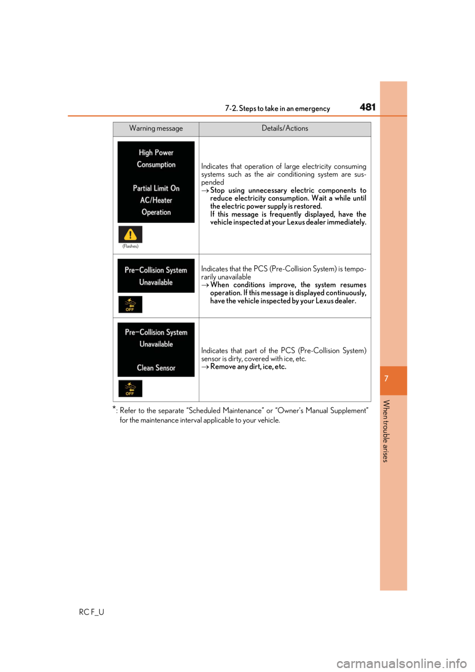
for the maintenance interval applicable to your vehicle. Indicates that operation of large electricity consuming
systems such as the air conditioning system are sus-
pended
Stop using unnecessary electric components to
reduce electricity consumpt ion. Wait a while until
the electric power supply is restored.
If this message is freque ntly displayed, have the
vehicle inspected at your Lexus dealer immediately.
Indicates that the PCS (Pre -Collision System) is tempo-
rarily unavailable
When conditions improve, the system resumes
operation. If this message is displayed continuously,
have the vehicle inspected by your Lexus dealer.
Indicates that part of th e PCS (Pre-Collision System)
sensor is dirty, covered with ice, etc.
Remove any dirt, ice, etc.Warning message Details/Actions(Flashes)
Page 482 of 636
482 7-2. Steps to take in an emergency
RC F_U ■
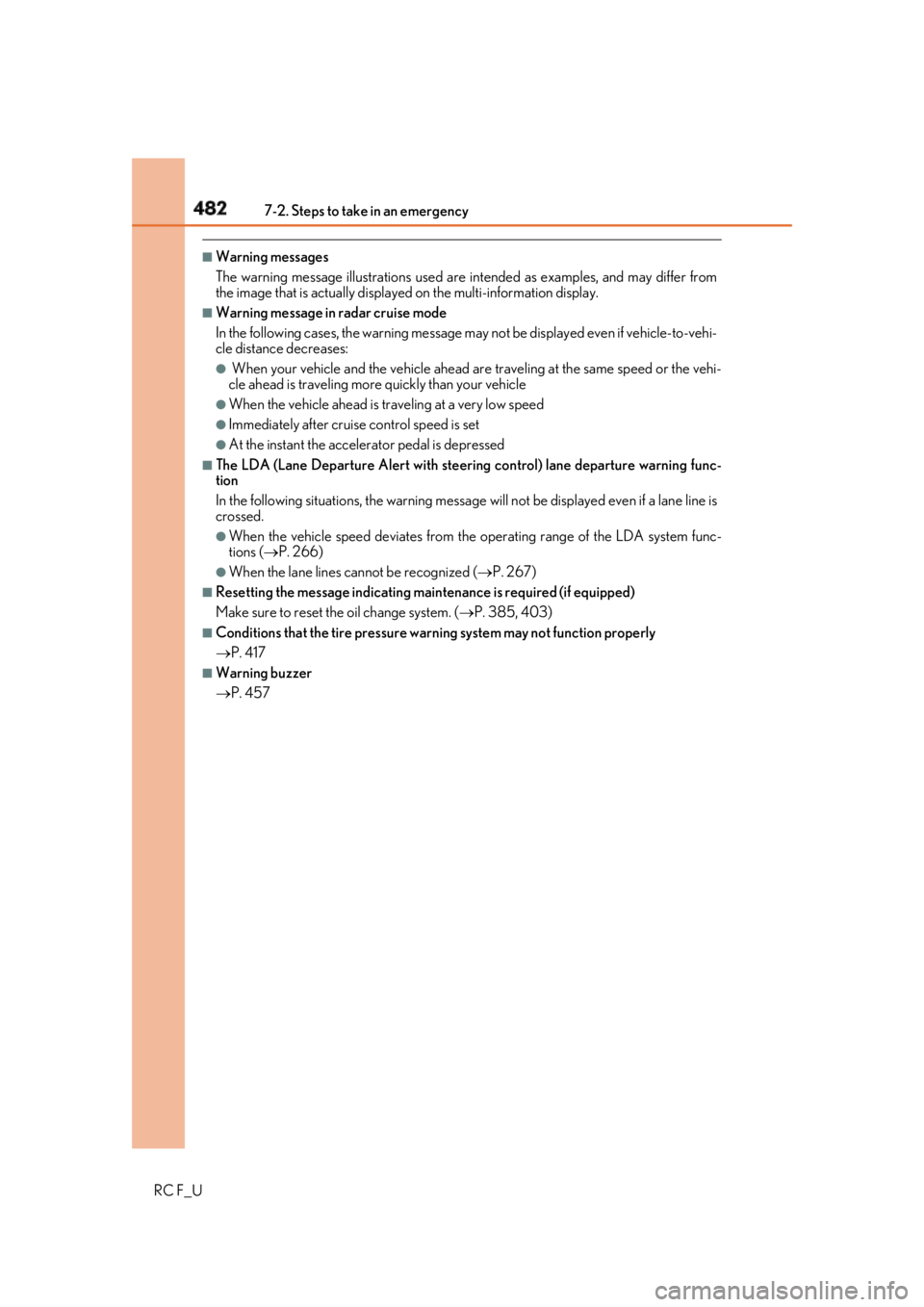
Warning messages
The warning message illustrations used are intended as examples, and may differ from
the image that is actually displaye d on the multi-information display.■
Warning message in radar cruise mode
In the following cases, the wa rning message may not be displa yed even if vehicle-to-vehi-
cle distance decreases: ●
When your vehicle and the vehicle ahead ar e traveling at the same speed or the vehi-
cle ahead is traveling more quickly than your vehicle●
When the vehicle ahead is traveling at a very low speed ●
Immediately after cruise control speed is set ●
At the instant the accelerator pedal is depressed ■
The LDA (Lane Departure Alert with steering control) lane departure warning func-
tion
In the following situations, th e warning message will not be displayed even if a lane line is
crossed. ●
When the vehicle speed deviates from the operating range of the LDA system func-
tions ( P. 266)●
When the lane lines cannot be recognized ( P. 267)■
Resetting the message indicating ma intenance is required (if equipped)
Make sure to reset the oil change system. ( P. 385, 403)■
Conditions that the tire pressure wa rning system may not function properly
P. 417 ■
Warning buzzer
P. 457
Page 483 of 636
4837-2. Steps to take in an emergency
RC F_U 7
When trouble arises Interior
buzzer Exterior
buzzer Warning message Details/Actions
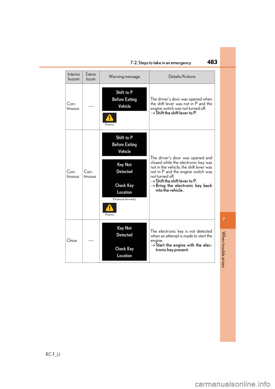
Con-
tinuous The driver’s door was opened when
the shift lever was not in P and the
engine switch was not turned off.
Shift the shift lever to P.
Con-
tinuous Con-
tinuous The driver’s door was opened and
closed while the electronic key was
not in the vehicle, the shift lever was
not in P and the engine switch was
not turned off.
Shift the shift lever to P.
Bring the electronic key back
into the vehicle.
Once The electronic key is not detected
when an attempt is made to start the
engine.
Start the engine with the elec-
tronic key present. (Flashes)
(Displayed alternately)
(Flashes)
Page 484 of 636
484 7-2. Steps to take in an emergency
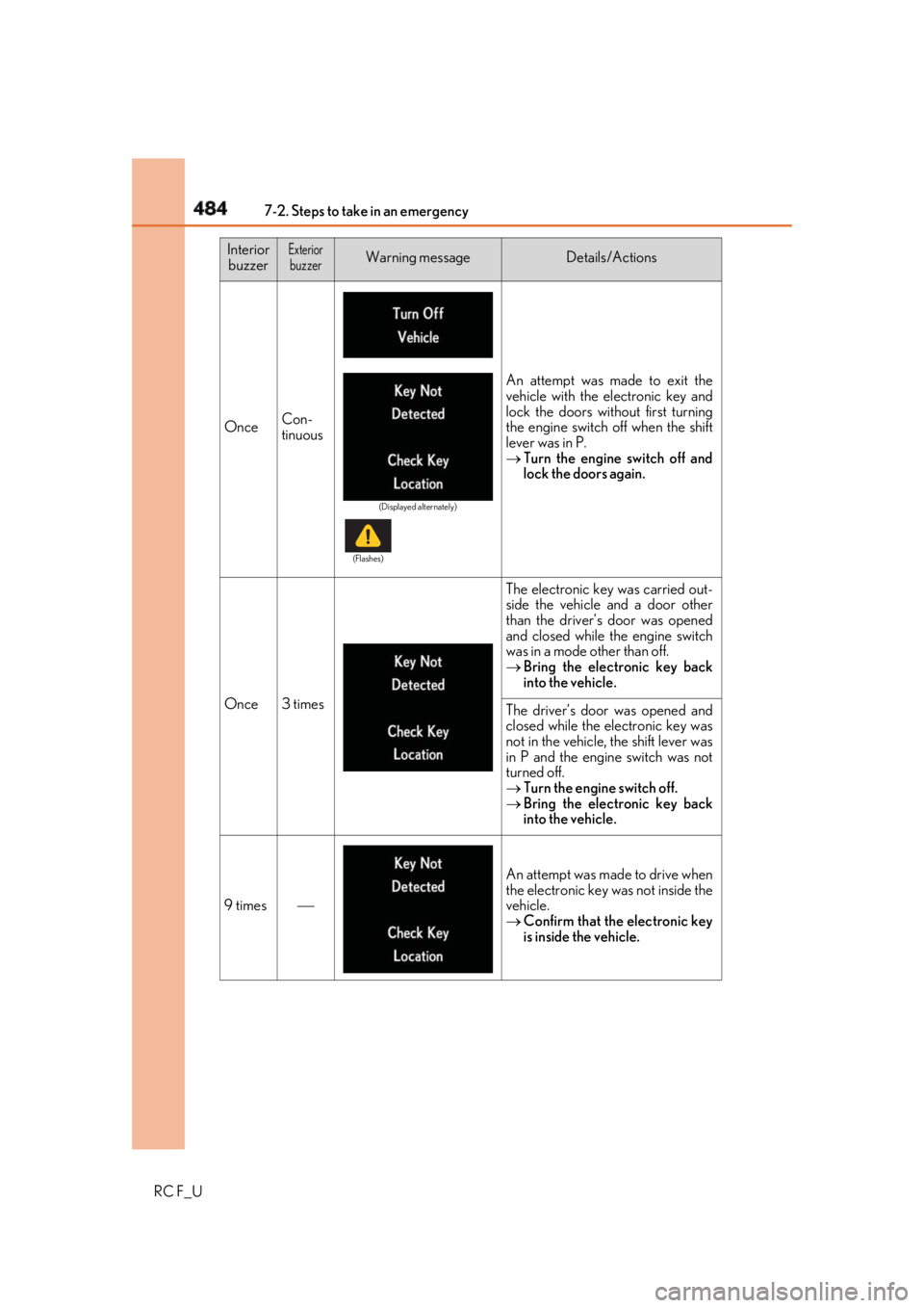
RC F_U Once Con-
tinuous An attempt was made to exit the
vehicle with the electronic key and
lock the doors without first turning
the engine switch off when the shift
lever was in P.
Turn the engine switch off and
lock the doors again.
Once 3 times The electronic key was carried out-
side the vehicle and a door other
than the driver’s door was opened
and closed while the engine switch
was in a mode other than off.
Bring the electronic key back
into the vehicle.
The driver’s door was opened and
closed while the electronic key was
not in the vehicle, the shift lever was
in P and the engine switch was not
turned off.
Turn the engine switch off.
Bring the electronic key back
into the vehicle.
9 times An attempt was made to drive when
the electronic key was not inside the
vehicle.
Confirm that the electronic key
is inside the vehicle.Interior
buzzer Exterior
buzzer Warning message Details/Actions (Displayed alternately)
(Flashes)
Page 485 of 636
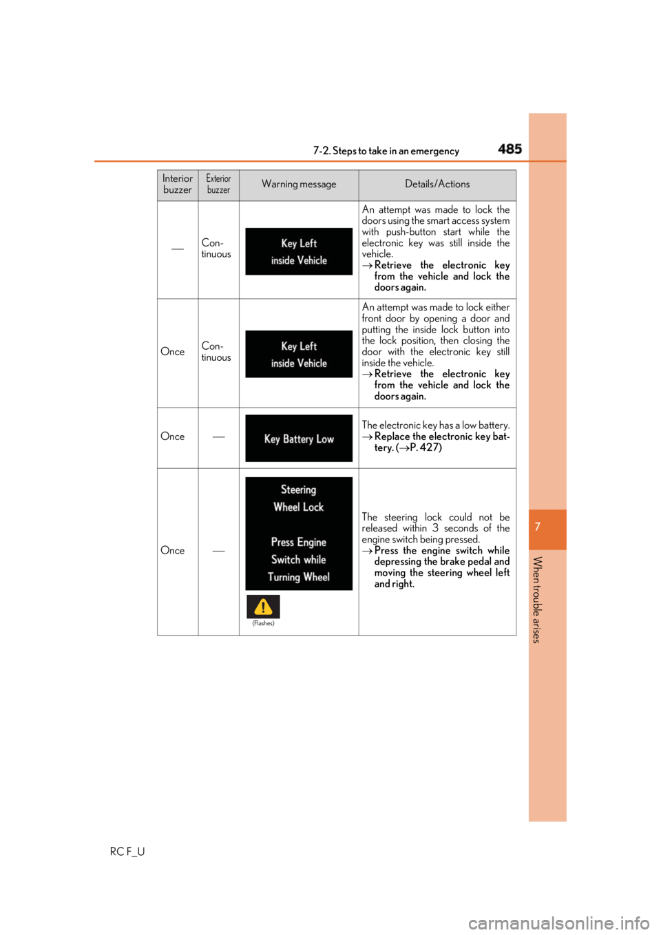
4857-2. Steps to take in an emergency
RC F_U 7
When trouble arises Con-
tinuous An attempt was made to lock the
doors using the smart access system
with push-button start while the
electronic key was still inside the
vehicle.
Retrieve the electronic key
from the vehicle and lock the
doors again.
Once Con-
tinuous An attempt was made to lock either
front door by opening a door and
putting the inside lock button into
the lock position, then closing the
door with the electronic key still
inside the vehicle.
Retrieve the electronic key
from the vehicle and lock the
doors again.
Once The electronic key has a low battery.
Replace the electronic key bat-
tery. ( P. 427)
Once The steering lock could not be
released within 3 seconds of the
engine switch being pressed.
Press the engine switch while
depressing the brake pedal and
moving the steering wheel left
and right.Interior
buzzer Exterior
buzzer Warning message Details/Actions
(Flashes)
Page 486 of 636
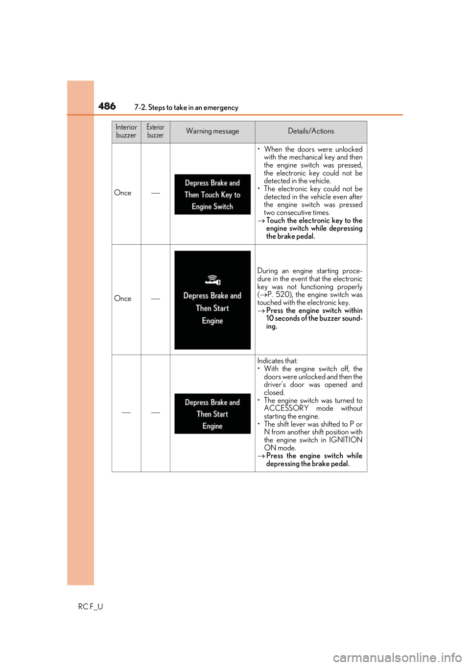
486 7-2. Steps to take in an emergency
RC F_U Once • When the doors were unlocked
with the mechanical key and then
the engine swit ch was pressed,
the electronic key could not be
detected in the vehicle.
• The electronic key could not be
detected in the vehicle even after
the engine switch was pressed
two consecutive times.
Touch the electronic key to the
engine switch while depressing
the brake pedal.
Once During an engine starting proce-
dure in the event that the electronic
key was not functioning properly
( P. 520), the engine switch was
touched with the electronic key.
Press the engine switch within
10 seconds of the buzzer sound-
ing.
Indicates that:
• With the engine switch off, the
doors were unlocked and then the
driver's door was opened and
closed.
• The engine switch was turned to
ACCESSORY mode without
starting the engine.
• The shift lever wa s shifted to P or
N from another shift position with
the engine switch in IGNITION
ON mode.
Press the engine switch while
depressing the brake pedal.Interior
buzzer Exterior
buzzer Warning message Details/Actions
Page 487 of 636
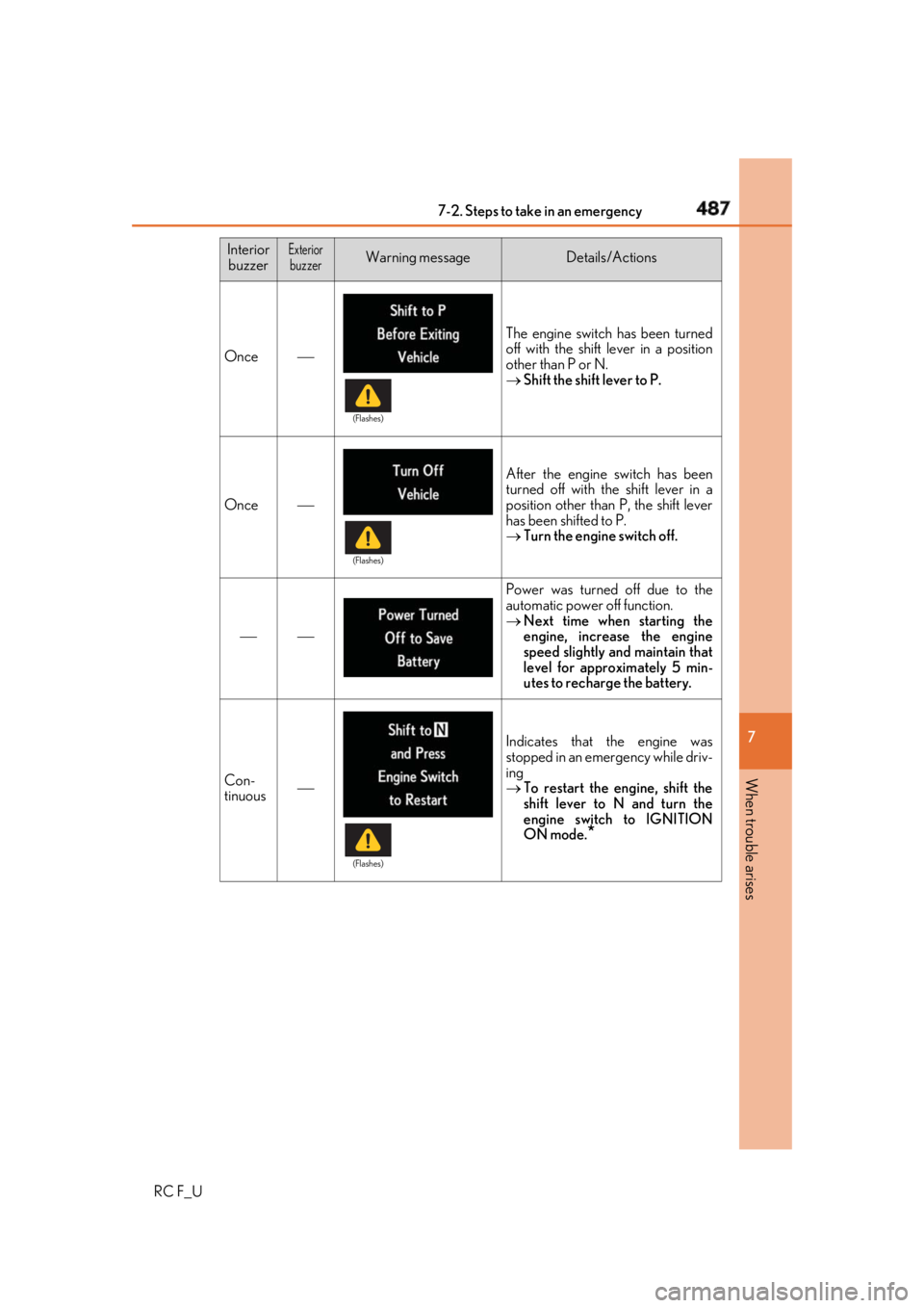
4877-2. Steps to take in an emergency
RC F_U 7
When trouble arises Once The engine switch has been turned
off with the shift lever in a position
other than P or N.
Shift the shift lever to P.
Once After the engine switch has been
turned off with the shift lever in a
position other than P, the shift lever
has been shifted to P.
Turn the engine switch off.
Power was turned off due to the
automatic power off function.
Next time when starting the
engine, increase the engine
speed slightly and maintain that
level for approximately 5 min-
utes to recharge the battery.
Con-
tinuous Indicates that the engine was
stopped in an emergency while driv-
ing
To restart the engine, shift the
shift lever to N and turn the
engine switch to IGNITION
ON mode.
*Interior
buzzer Exterior
buzzer Warning message Details/Actions (Flashes)
(Flashes)
(Flashes)
Page 488 of 636
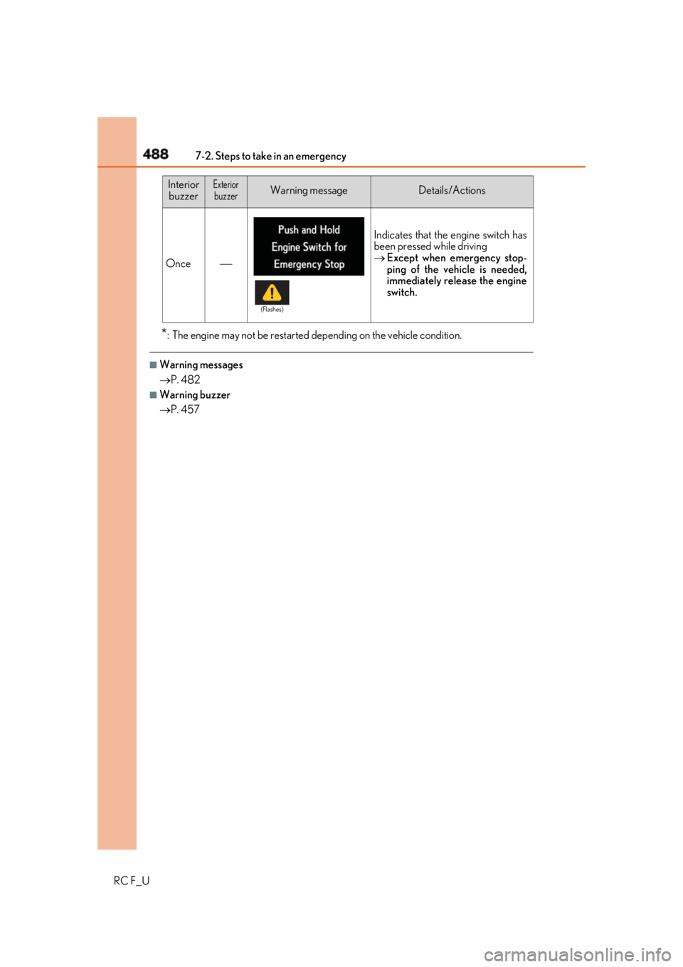
488 7-2. Steps to take in an emergency
RC F_U * : The engine may not be restarted depending on the vehicle condition.■
Warning messages
P. 482 ■
Warning buzzer
P. 457Once Indicates that the engine switch has
been pressed while driving
Except when emergency stop-
ping of the vehicle is needed,
immediately release the engine
switch.Interior
buzzer Exterior
buzzer Warning message Details/Actions (Flashes)
Page 489 of 636
4897-2. Steps to take in an emergency
RC F_U 7
When trouble arises ●
Stop the vehicle in a safe pl ace on a hard, flat surface.●
Set the parking brake. ●
Shift the shift lever to P. ●
Stop the engine. ●
Turn on the emergency flashers. ( P. 442)If you have a flat tire (vehicles with a spare tire) Your vehicle is equipped with a spare tire. The flat tire can be replaced with
the spare tire.
For details about tires: P. 412WARNING ■
If you have a flat tire
Do not continue driving with a flat tire.
Driving even a short distance with a flat ti re can damage the tire and the wheel beyond
repair, which could re sult in an accident.
Before jacking up the vehicle
Page 490 of 636
490 7-2. Steps to take in an emergency
RC F_U
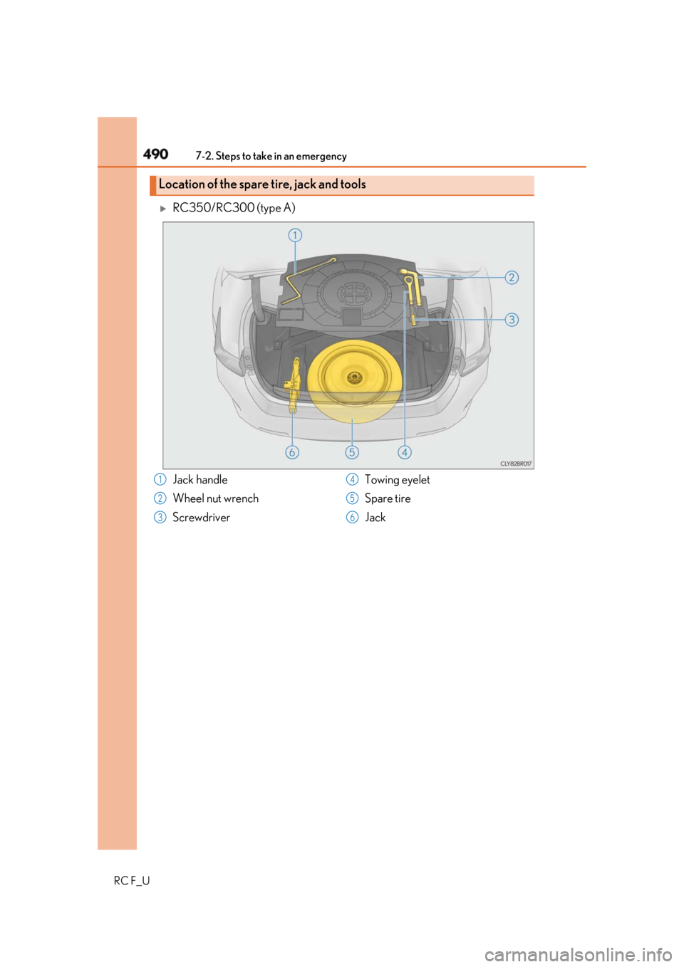
RC350/RC300 (type A)
Location of the spare tire, jack and tools
Jack handle
Wheel nut wrench
Screwdriver Towing eyelet
Spare tire
Jack1
2
3 4
5
6