ESP LEXUS RX350 2020 User Guide
[x] Cancel search | Manufacturer: LEXUS, Model Year: 2020, Model line: RX350, Model: LEXUS RX350 2020Pages: 516, PDF Size: 17.3 MB
Page 63 of 516

631-3. Lexus Enform
1
For safety and security
response-center agent, who can help
with a wide range of needs, such as:
towing, flat tire, fuel delivery, etc. For a
description of the Roadside Assistance
services and their limitations, please
see the Safety Connect Terms and
Conditions, which are available at
Lexus.com.
Important! Read this information about
exposure to radio frequency signals
before using Safety Connect;
The Safety Connect system installed in
your vehicle is a low-power radio trans-
mitter and receiver. It receives and also
sends out radio frequency (RF) signals.
In August 1996, the Federal Commu-
nications Commission (FCC) adopted
RF exposure guidelines with safety lev-
els for mobile wireless phones. Those
guidelines are consistent with the
safety standards previously set by the
following U.S. and international stan-
dards bodies.
ANSI (American National Stan-
dards Institute) C95.1 [1992]
NCRP (National Council on Radia-
tion Protection and Measurement)
Report 86 [1986]
ICNIRP (International Commission
on Non-Ionizing Radiation Protec-
tion) [1996]
Those standards were based on com-
prehensive and periodic evaluations of
the relevant scientific literature. Over 120 scientists, engineers, and physi-
cians from universities, and govern-
ment health agencies and industries
reviewed the available body of
research to develop the ANSI Stan-
dard (C95.1).
The design of Safety Connect com-
plies with the FCC guidelines in addi-
tion to those standards.
Safety information for Safety
Connect
Page 66 of 516

661-4. Theft deterrent system
WARNING
■Certifications for the engine immobi-
lizer system
Changes or modifications not expressly
approved by the party responsible for
compliance could void the user’s author-
ity to operate the equipment.
NOTICE
■To ensure the system operates cor-
rectly
Do not modify or remove the system. If
modified or removed, the proper opera-
tion of the system cannot be guaranteed.
Page 77 of 516

772-1. Instrument cluster
2
Vehicle status information and indicators
speed, a ring-shaped indicator will be
displayed on the tachometer.
The desired engine speed at which the Rev
indicator will begin to be displayed can be
set on of the multi-information display.
( P.79)
■Rev peak (F SPORT models)
The engine speed reaches or exceeds
5000 rpm, an afterimage of the
tachometer will be displayed at the
highest engine speed for approxi-
mately 1 second.
■The meters and display illuminate when
The engine switch is in IGNITION ON
mode.
■Outside temperature display
●In the following situations, the correct
outside temperature may not be dis-
played, or the display may take longer
than normal to change:
• When stopped, or driving at low speeds (less than 12 mph [20 km/h])
• When the outside temperature has changed suddenly (at the entrance/exit of
a garage, tunnel, etc.)
●When “--” or “E” is displayed, the system
may be malfunctioning. Take your vehicle
to your Lexus dealer.
■Liquid crystal display
Small spots or light sp ots may appear on the
display. This phenomenon is characteristic
of liquid crystal disp lays, and there is no
problem continuing to use the display.
■Customization
The gauges and meters can be customized
on of the multi-information display.
( P.83)
WARNING
■The information display at low tem-
peratures
Allow the interior of the vehicle to warm
up before using the liquid crystal infor-
mation display. At extremely low tem-
peratures, the information display
monitor may respond slowly, and display
changes may be delayed.
For example, there is a lag between the
driver’s shifting and the new gear number
appearing on the display. This lag could
cause the driver to downshift again,
causing rapid and excessive engine brak-
ing and possibly an accident resulting in
death or injury.
NOTICE
■To prevent damage to the engine and
its components
●Do not let the indicator needle of the
tachometer enter the red zone, which
indicates the maximum engine speed.
●The engine may be overheating if the
engine coolant temperature gauge is
in the red zone (H). In this case, imme-
diately stop the vehicle in a safe place,
and check the engine after it has
cooled completely. ( P.447)
Page 83 of 516

832-1. Instrument cluster
2
Vehicle status information and indicators
tire inflation pressure after the engine
switch is turned to IGNITION ON mode.
It may also take a few minutes to display
the tire inflation pressure after inflation
pressure has been adjusted.
• “---” may be displayed if the tire position information cannot be determined due to
unfavorable radio wave conditions.
• Tire inflation pressure changes with tem- perature. The displayed values may also
be different from the values measured
using a tire pressure gauge.
Select to display the following naviga-
tion system-linked information.
Route guidance
Compass display (heading-up dis-
play)
Select to enable selection of an audio
source or track on the meter using the
meter control switches.
Select to display the operational status
of the following systems:
LTA (Lane Tracing Assist) ( P.218)
RSA (Road Sign Assist) (if
equipped) ( P.227)
Dynamic radar cruise control with
full-speed range ( P.230)
■Meter display settings that can be
changed
Clock
Select to switch between 12-hour display
and 24-hour display.
Language
Select to change the language displayed.
Units
Select to change the units of measure dis-
played.
Eco Driving Indicator Light
( P.81)
Select to enable/disable the Eco Driving
Indicator Light.
Switch settings
Select to display how to change the top
screen.
Drive information 1/Drive informa-
tion 2/Drive information 3
Select to select up to 2 items ( P.80) that
will be displayed on each Drive information
screen (Drive information 1 screen, Drive
information 2 screen, and Drive informa-
tion 3 screen) respectively.
Pop-up display
Select to enable/disable the pop-up dis-
play.
• Intersection guidance (if equipped)
• Incoming calls
• Brightness adjustment
Color (except F SPORT models)
Select to set the color of the cursor on the
multi-information display.
Needle (F SPORT models)
Navigation system-linked dis-
play (if equipped)
Audio system-linked display
Driving assist system information
Settings display
Page 84 of 516

842-1. Instrument cluster
Select to set the tachometer needle color.
Rev indicator (F SPORT models)
( P.76)
• Select to enable/disable the Rev indica-
tor.
• Select to set the desired engine speed at which the Rev indicator will begin to be
displayed.
Selectable engine speed range:
2000 rpm to 6500 rpm
Rev peak (F SPORT models)
( P.77)
Select to enable/dis able the Rev peak.
Default setting
Select to reset the meter display settings to
the default setting.
■Vehicle functions and settings that
can be changed
P.470
■Background color of the indicator/shift
position display area (except F SPORT
models)
The background color of the indicator/shift
position display area is changed according
to the driving mode as follows ( P.274):
●Eco drive mode: Blue
●Sport mode: Red
■Suspension of the settings display
●Some settings cannot be changed while
driving. When changi ng settings, park
the vehicle in a safe place.
●If a warning message is displayed, opera-
tion of the settings display will be sus-
pended.
Displays suggestions to the driver in
the following situations. To select a
response to a displayed suggestion,
use the meter control switches.
■Suggestion to enable the power
back door
If the power back door system is dis-
abled (setting on set to off) and the
power back door switch on the instru-
ment panel is operated, a suggestion
message will be displayed asking if you
wish to enable the power back door
system.
To enable the power back door system,
select “Yes”.
After enabling the power back door sys-
tem, press the power back door switch
again to open or close the power back
door.
WARNING
■Cautions during setting up the dis-
play
As the engine needs to be running
during setting up the display, en sure that
the vehicle is parked in a place with ade-
quate ventilation. In a closed area such as
a garage, exhaust gases including harm-
ful carbon monoxide (CO) may collect
and enter the vehicle. This may lead to
death or a serious health hazard.
NOTICE
■While setting up the display
To prevent battery discharge, ensure that
the engine is running while setting up the
display features.
Suggestion function
Page 87 of 516

872-1. Instrument cluster
2
Vehicle status information and indicators
refer to the explanations of each system.
Vehicle speed display area
Displays the following items:
• Vehicle speed
• Speed limit (vehicles with a navigation system) (U.S.A. only)
• Road sign icons recognized by the RSA ( P.227)
Eco Driving Indicator/Tachometer ( P.90)
Shift position display ( P.180)
HUD (Head-up display) switch ( P.87)
■Head-up display
The head-up display may seem dark or hard
to see when viewed through sunglasses,
especially polarized su nglasses. Adjust the
brightness of the head-up display or
remove your sunglasses.
■Enabling/Disabling the head-up
display
Press the HUD (Head-up display)
switch.
E
F
G
H
WARNING
■Before using the head-up display
●Check that the position and brightness
of the head-up display image does not
interfere with safe driving. Incorrect
adjustment of the image’s position or
brightness may obstruct the driver’s
view and lead to an accident, resulting
in death or serious injury.
●Do not continuously look at the
head-up display while driving as you
may fail to see pedestrians, objects on
the road, etc. ahead of the vehicle.
NOTICE
■To prevent damage to components
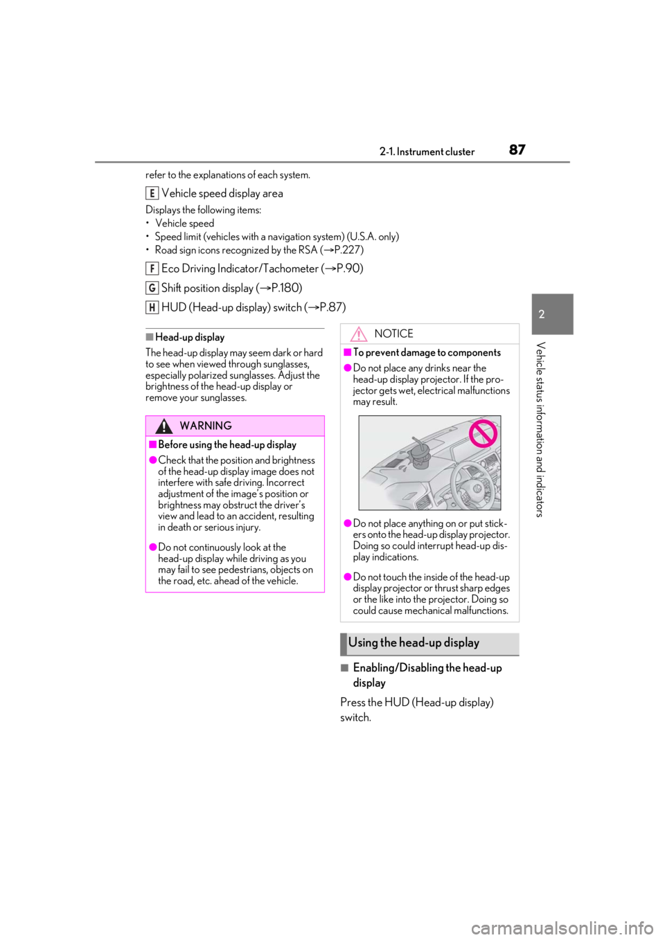
●Do not place any drinks near the
head-up display projector. If the pro-
jector gets wet, electrical malfunctions
may result.
●Do not place anything on or put stick-
ers onto the head-up display projector.
Doing so could interrupt head-up dis-
play indications.
●Do not touch the inside of the head-up
display projector or thrust sharp edges
or the like into the projector. Doing so
could cause mechanical malfunctions.
Using the head-up display
Page 99 of 516

993-2. Opening, closing and locking the doors
3
Before driving
mechanical key. (P.441)
■Customization
Some functions can be customized.
( P.470)
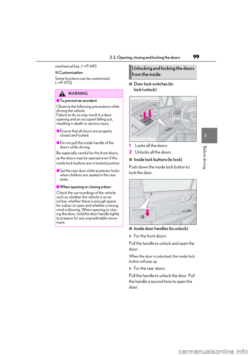
■Door lock switches (to
lock/unlock)
1 Locks all the doors
2 Unlocks all the doors
■Inside lock buttons (to lock)
Push down the inside lock button to
lock the door.
■Inside door handles (to unlock)
For the front doors
Pull the handle to unlock and open the
door.
When the door is unlo cked, the inside lock
button will pop up.
For the rear doors
Pull the handle to unlock the door. Pull
the handle a second time to open the
door.
WARNING
■To prevent an accident
Observe the following precautions while
driving the vehicle.
Failure to do so may result in a door
opening and an occupant falling out,
resulting in death or serious injury.
●Ensure that all doors are properly
closed and locked.
●Do not pull the inside handle of the
doors while driving.
Be especially careful for the front doors,
as the doors may be opened even if the
inside lock buttons are in locked position.
●Set the rear door ch ild-protector locks
when children are seated in the rear
seats.
■When opening or closing a door
Check the surroundings of the vehicle
such as whether the vehicle is on an
incline, whether ther e is enough space
for a door to open and whether a strong
wind is blowing. When opening or clos-
ing the door, hold the door handle tightly
to prepare for any unpredictable move-
ment.
Unlocking and locking the doors
from the inside
Page 137 of 516

1373-3. Adjusting the seats
3
Before driving
■Recall procedure
1 Make sure that the doors are
locked before recalling the driving
position. Carry the electronic key
that has been registered to the driv-
ing position, and then unlock and
open the driver’s door using the
smart access system with push-but-
ton start or wireless remote control.
The driving position will move to the
recorded position (not including the steer-
ing wheel and head-up display [if
equipped]). However, the seat will move to
a position slightly behind the recorded
position in order to make entering the vehi-
cle easier.
If the driving position is in a position that
has already been recorded, the seat and
outside rear view mirrors will not move.
2Turn the engine switch to ACCES-
SORY mode or IGNITION ON
mode, or fasten a seat belt.
The seat, steering wheel and head-up dis-
play (if equipped) will move to the
recorded position.
■Recalling the driving position using the
memory recall function
●Different driving positions can be regis-
tered for each electronic key. Therefore,
the driving position that is recalled may
be different depending on the key being
carried.
●If a door other than the driver’s door is
unlocked with the smart access system
with push-button start, the driving posi-
tion cannot be recalled. In this case, press
the driving position button which has
been set.
■Customization
Some functions can be customized.
( P.470)
■Front seats
1 Up
Pull the head restraints up.
2Down
Push the head restra int down while press-
ing the lock release button .
Head restraints
Head restraints are provided for all
seats.
WARNING
■Head restraint precautions
Observe the following precautions
regarding the head re straints. Failure to
do so may result in death or serious
injury.
●Use the head restraints designed for
each respective seat.
●Adjust the head restraints to the cor-
rect position at all times.
●After adjusting the head restraints,
push down on them and make sure
they are locked in position.
●Do not drive with the head restraints
removed.
Adjusting a head restraint verti-
cally
A
Page 141 of 516

1413-4. Adjusting the steering wheel and mirrors
3
Before driving
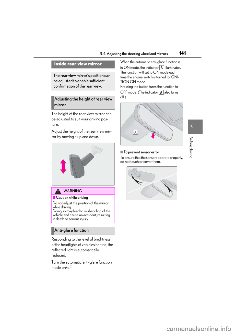
The height of the rear view mirror can
be adjusted to suit your driving pos-
ture.
Adjust the height of the rear view mir-
ror by moving it up and down.
Responding to the level of brightness
of the headlights of vehicles behind, the
reflected light is automatically
reduced.
Turn the automatic anti-glare function
mode on/off
When the automatic anti-glare function is
in ON mode, the indicator illuminates.
The function will set to ON mode each
time the engine switch is turned to IGNI-
TION ON mode.
Pressing the button turns the function to
OFF mode. (The indicator also turns
off.)
■To prevent sensor error
To ensure that the sensors operate properly,
do not touch or cover them.
Inside rear view mirror
The rear view mirror’s position can
be adjusted to enable sufficient
confirmation of the rear view.
Adjusting the height of rear view
mirror
WARNING
■Caution while driving
Do not adjust the position of the mirror
while driving.
Doing so may lead to mishandling of the
vehicle and cause an accident, resulting
in death or serious injury.
Anti-glare function
A
A
Page 146 of 516

1463-5. Opening, closing the windows and moon roof
If you release the switch while the window is
moving, start again from the beginning.
If the window reverses and cannot be fully
closed or opened, have the vehicle
inspected by your Lexus dealer.
■Door lock linked window operation
●The power windows can be opened and
closed using the mechanical key.*
( P.442)
●The power windows can be opened using
the wireless remote control.* ( P.97)
*: These settings must be customized at
your Lexus dealer.
■Alarm
The alarm may be triggered if the alarm is
set and a power window is closed using the
door lock linked power window operation
function. ( P.67)
■Power windows open warning buzzer
A buzzer sounds and a message is shown
on the multi-information display in the
instrument cluster when the engine switch
is turned off and the driver’s door is opened
with the power windows open.
■Customization
Some functions can be customized.
( P.470)
WARNING
Observe the following precautions.
Failing to do so may result in death or
serious injury.
■Closing the windows
●The driver is responsible for all the
power window operations, including
the operation for the passengers. In
order to prevent accidental operation,
especially by a child, do not let a child
operate the power windows. It is possi-
ble for children an d other passengers
to have body parts caught in the power
window. Also, when riding with a child,
it is recommended to use the window
lock switch. (
P.147)
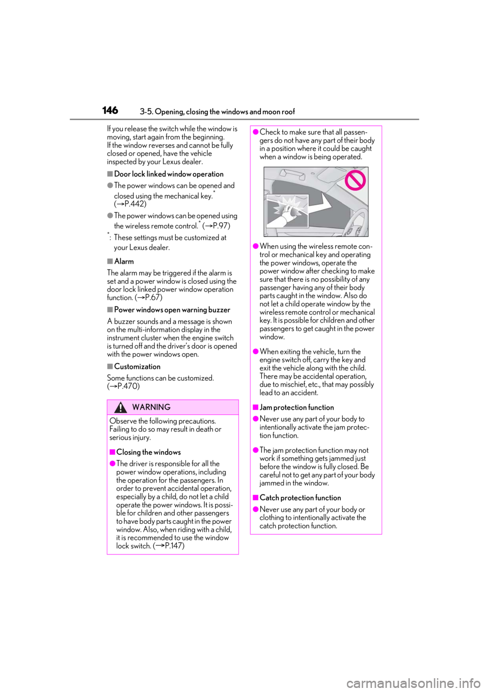
●Check to make sure that all passen-
gers do not have any part of their body
in a position where it could be caught
when a window is being operated.
●When using the wireless remote con-
trol or mechanical key and operating
the power windows, operate the
power window after checking to make
sure that there is no possibility of any
passenger having any of their body
parts caught in the window. Also do
not let a child operate window by the
wireless remote control or mechanical
key. It is possible for children and other
passengers to get caught in the power
window.
●When exiting the vehicle, turn the
engine switch off, carry the key and
exit the vehicle along with the child.
There may be accidental operation,
due to mischief, etc., that may possibly
lead to an accident.
■Jam protection function
●Never use any part of your body to
intentionally activa te the jam protec-
tion function.
●The jam protection function may not
work if something gets jammed just
before the window is fully closed. Be
careful not to get any part of your body
jammed in the window.
■Catch protection function
●Never use any part of your body or
clothing to intentionally activate the
catch protection function.