turn signal LEXUS RX350 2021 User Guide
[x] Cancel search | Manufacturer: LEXUS, Model Year: 2021, Model line: RX350, Model: LEXUS RX350 2021Pages: 508, PDF Size: 10.33 MB
Page 192 of 508

1924-3. Operating the lights and wipers
out its headlights turned on is detected.
●House lights, street lights, traffic signals,
and illuminated billboards or signs and
other reflective objects may cause the
high beams to change to the low beams,
or the low beams to remain on.
●The following factors may affect the
amount of time taken for the high beams
to turn on or off:
• The brightness of the headlights, fog
lights, and tail lights of vehicles ahead
• The movement and direction of vehicles ahead
• When a vehicle ahead only has opera- tional lights on one side
• When a vehicle ahead is a two-wheeled
vehicle
• The condition of the road (gradient, curve, condition of th e road surface, etc.)
• The number of passengers and amount of luggage in the vehicle
●The high beams may turn on or off unex-
pectedly.
●Bicycles or similar vehicles may not be
detected.
●In the following situations the system may
not be able to correctly detect the sur-
rounding brightness le vel. This may cause
the low beams to remain on or the high
beams to flash or dazzle pedestrians or
vehicles ahead. In such a case, it is neces-
sary to manually switch between the high
and low beams.
• When driving in inclement weather
(heavy rain, snow, fog, sandstorms, etc.)
• When the windshield is obscured by fog, mist, ice, dirt, etc.
• When the windshield is cracked or dam- aged
• When the camera sensor is deformed or
dirty
• When the temperature of the camera sensor is extremely high
• When the surrounding brightness level is equal to that of head lights, tail lights or
fog lights
• When headlights or tail lights of vehicles
ahead are turned off, dirty, changing
color, or not aimed properly
• When the vehicle is hit by water, snow,
dust, etc. from a preceding vehicle
• When driving through an area of inter-mittently changing brightness and dark-
ness
• When frequently and repeatedly driving
ascending/descending roads, or roads
with rough, bumpy or uneven surfaces
(such as stone-paved roads, gravel roads,
etc.)
• When frequently and repeatedly taking curves or driving on a winding road
• When there is a highly reflective object ahead of the vehicle, such as a sign or
mirror
• When the back of a preceding vehicle is highly reflective, such as a container on a
truck
• When the vehicle’s headlights are dam- aged or dirty, or are not aimed properly
• When the vehicle is listing or titling due to
a flat tire, a trailer being towed, etc.
• When the headlights are changed between the high beams and low beams
repeatedly in an abnormal manner
• When the driver believes that the high beams may be flashing or dazzling
pedestrians or other drivers
■Temporarily lowering sensor sensitivity
The sensitivity of the sensor can be tempo-
rarily lowered.
1 Turn the engine switch off while the fol-
lowing conditions are met.
●The headlight switch is in or .
●The headlight switch lever is in high beam
position.
●Automatic High Beam switch is on.
2 Turn the engine switch to IGNITION
ON mode.
3 Within 60 seconds after step 2 , repeat
pulling the headlight switch lever to the
original position then pushing it to the
high beam position quickly 10 times,
then leave the lever in high beam posi-
tion.
4 If the sensitivity is changed, the Auto-
matic High Beam indicator is turn on
and off 3 times.
Automatic High Beam (headlights) may
turn on even when the vehicle is stopped.
Page 219 of 508
2194-5. Using the driving support systems
4
Driving
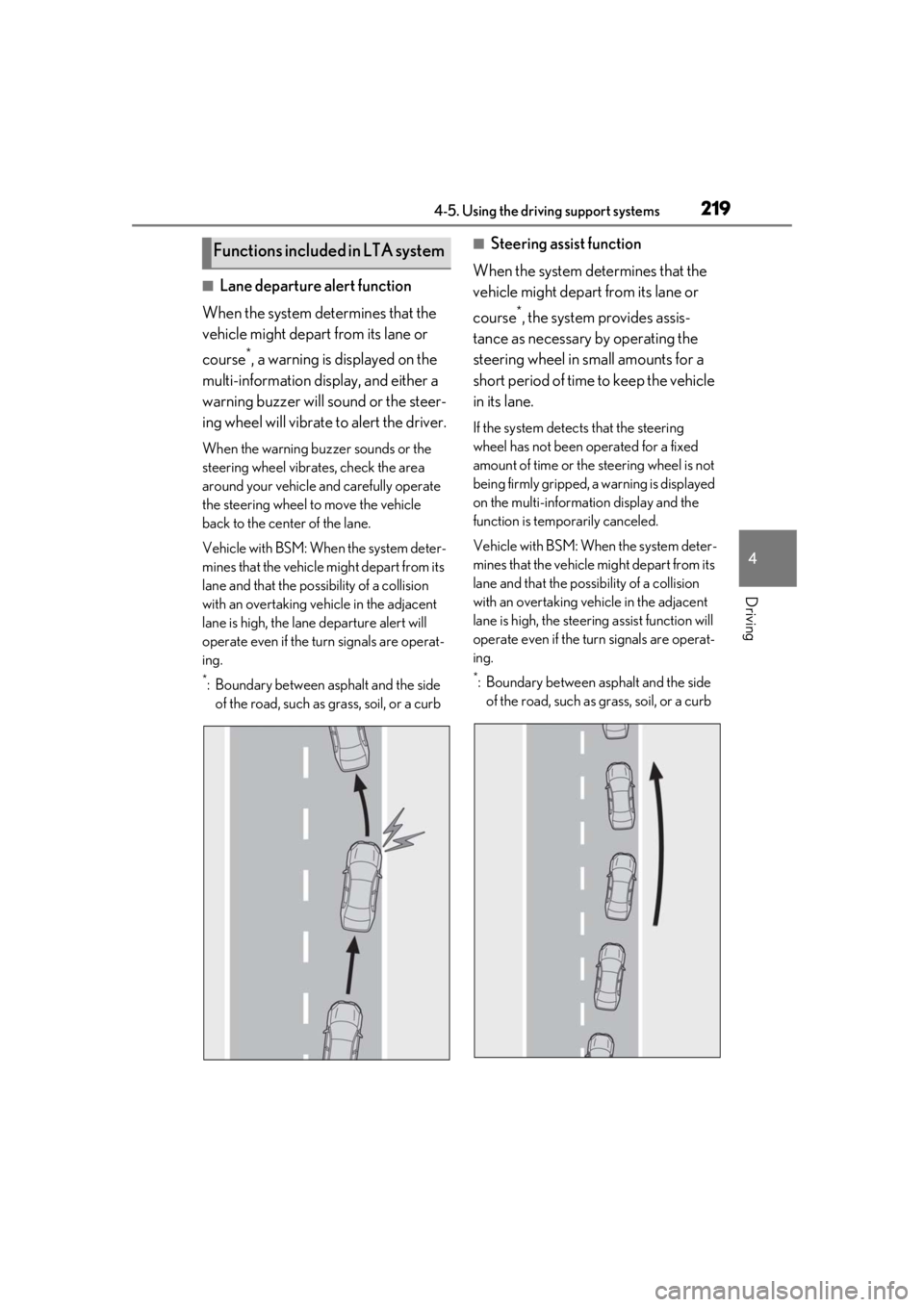
■Lane departure alert function
When the system determines that the
vehicle might depart from its lane or
course
*, a warning is displayed on the
multi-information display, and either a
warning buzzer will sound or the steer-
ing wheel will vibrate to alert the driver.
When the warning buzzer sounds or the
steering wheel vibrates, check the area
around your vehicle and carefully operate
the steering wheel to move the vehicle
back to the center of the lane.
Vehicle with BSM: When the system deter-
mines that the vehicle might depart from its
lane and that the possibility of a collision
with an overtaking vehicle in the adjacent
lane is high, the lane departure alert will
operate even if the turn signals are operat-
ing.
*: Boundary between asphalt and the side of the road, such as grass, soil, or a curb
■Steering assist function
When the system determines that the
vehicle might depart from its lane or
course
*, the system provides assis-
tance as necessary by operating the
steering wheel in small amounts for a
short period of time to keep the vehicle
in its lane.
If the system detects that the steering
wheel has not been operated for a fixed
amount of time or the steering wheel is not
being firmly gripped, a warning is displayed
on the multi-informat ion display and the
function is temporarily canceled.
Vehicle with BSM: When the system deter-
mines that the vehicle might depart from its
lane and that the po ssibility of a collision
with an overtaking vehicle in the adjacent
lane is high, the steering assist function will
operate even if the turn signals are operat-
ing.
*: Boundary between asphalt and the side of the road, such as grass, soil, or a curb
Functions included in LTA system
Page 222 of 508
2224-5. Using the driving support systems
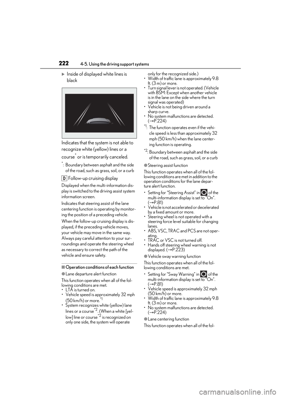
Inside of displayed white lines is
black
Indicates that the system is not able to
recognize white (yellow) lines or a
course
* or is temporarily canceled.
*: Boundary between asphalt and the side of the road, such as grass, soil, or a curb
Follow-up cruising display
Displayed when the mu lti-information dis-
play is switched to the driving assist system
information screen.
Indicates that steering assist of the lane
centering function is operating by monitor-
ing the position of a preceding vehicle.
When the follow-up cruising display is dis-
played, if the preceding vehicle moves,
your vehicle may move in the same way.
Always pay careful attention to your sur-
roundings and operate the steering wheel
as necessary to correct the path of the
vehicle and ensure safety.
■Operation conditions of each function
●Lane departure alert function
This function operates when all of the fol-
lowing conditions are met.
• LTA is turned on.
• Vehicle speed is approximately 32 mph (50 km/h) or more.
*1
•System recognizes wh ite (yellow) lane
lines or a course*2. (When a white [yel-
low] line or course*2 is recognized on
only one side, the system will operate only for the recognized side.)
• Width of traffic lane is approximately 9.8 ft. (3 m) or more.
• Turn signal lever is not operated. (Vehicle with BSM: Except when another vehicle
is in the lane on the side where the turn
signal was operated)
• Vehicle is not being driven around a sharp curve.
• No system malfunctions are detected. ( P.224)
*1: The function operates even if the vehi-
cle speed is less than approximately 32
mph (50 km/h) when the lane center-
ing function is operating.
*2: Boundary between asphalt and the side of the road, such as grass, soil, or a curb
●Steering assist function
This function operates when all of the fol-
lowing conditions are met in addition to the
operation conditions for the lane depar-
ture alert function.
• Setting for “Steering Assist” in of the multi-information display is set to “On”.
( P.81)
• Vehicle is not acceler ated or decelerated
by a fixed amount or more.
• Steering wheel is not operated with a steering force level su itable for changing
lanes.
• ABS, VSC, TRAC and PCS are not oper- ating.
• TRAC or VSC is not turned off.
• Hands off steering wheel warning is not
displayed. ( P.223)
●Vehicle sway warning function
This function operates when all of the fol-
lowing conditions are met.
• Setting for “Sway Warning” in of the multi-information display is set to “On”.
( P.81)
• Vehicle speed is approximately 32 mph
(50 km/h) or more.
• Width of traffic lane is approximately 9.8 ft. (3 m) or more.
• No system malfunctions are detected. ( P.224)
●Lane centering function
This function operates when all of the fol-
D
Page 223 of 508
2234-5. Using the driving support systems
4
Driving
lowing conditions are met.
• LTA is turned on.
• Setting for “Steering Assist” and “Lane Center” in of the multi-information
display are set to “On”. ( P.81)
• This function recognizes white (yellow) lane lines or the position of a preceding
vehicle (except when the preceding vehi-
cle is small, such as a motorcycle).
• The dynamic radar cruise control with
full-speed range is operating in vehi-
cle-to-vehicle distance control mode.
• Width of traffic lane is approximately 10
to 13 ft. (3 to 4 m).
• Turn signal lever is not operated.
• Vehicle is not being driven around a sharp curve.
• No system malfunctions are detected. ( P.224)
• Vehicle does not acc elerate or deceler-
ate by a fixed amount or more.
• Steering wheel is not operated with a
steering force level su itable for changing
lanes.
• ABS, VSC, TRAC and PCS are not oper-
ating.
• TRAC or VSC is not turned off.
• Hands off steering wheel warning is not displayed. ( P.223)
• The vehicle is being driven in the center of a lane.
• Steering assist function is not operating.
■Temporary cancelation of functions
●When operation conditions are no longer
met, a function may be temporarily can-
celed. However, when the operation con-
ditions are met again, operation of the
function is automa tically restored.
( P.222)
●If the operation conditions ( P.222) are
no longer met while the lane centering
function is operating, the steering wheel
may vibrate and the buzzer may sound to
indicate that the function has been tem-
porarily canceled. However, if the “Alert”
customization setting is set to ,
the system will notify the driver by vibrat-
ing the steering wheel instead of sound-
ing the buzzer.
■Steering assist function/lane centering
function
●Depending on the vehicle speed, lane
departure situation, road conditions, etc.,
the driver may not feel the function is
operating or the function may not oper-
ate at all.
●The steering control of the function is
overridden by the driver’s steering wheel
operation.
●Do not attempt to test the operation of
the steering assist function.
■Lane departure alert function
●The warning buzzer may be difficult to
hear due to external noise, audio play-
back, etc. Also, it may be difficult to feel
steering wheel vibrations due to the road
conditions, etc.
●If the edge of the course* is not clear or
straight, the lane departure alert function
may not operate.
●Vehicle with BSM: It may not be possible
for the system to determine if there is a
danger of a collision with a vehicle in an
adjacent lane.
●Do not attempt to test the operation of
the lane departure alert function.
*: Boundary between asphalt and the side
of the road, such as grass, soil, or a curb
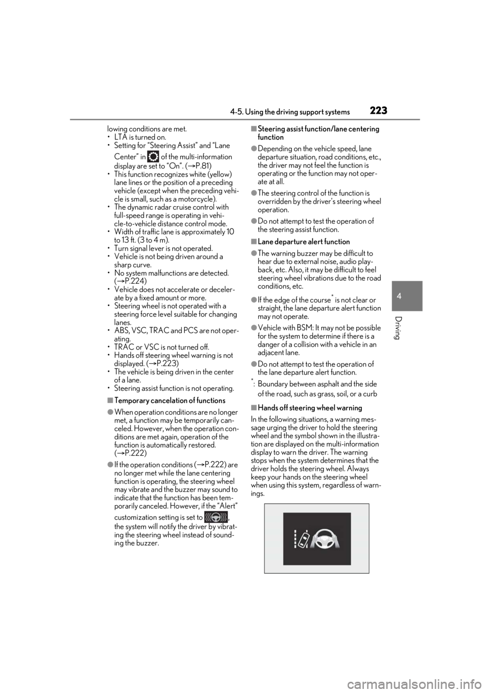
■Hands off steering wheel warning
In the following situations, a warning mes-
sage urging the driver to hold the steering
wheel and the symbol sh own in the illustra-
tion are displayed on the multi-information
display to warn the driver. The warning
stops when the system determines that the
driver holds the steering wheel. Always
keep your hands on the steering wheel
when using this system , regardless of warn-
ings.
Page 230 of 508
2304-5. Using the driving support systems
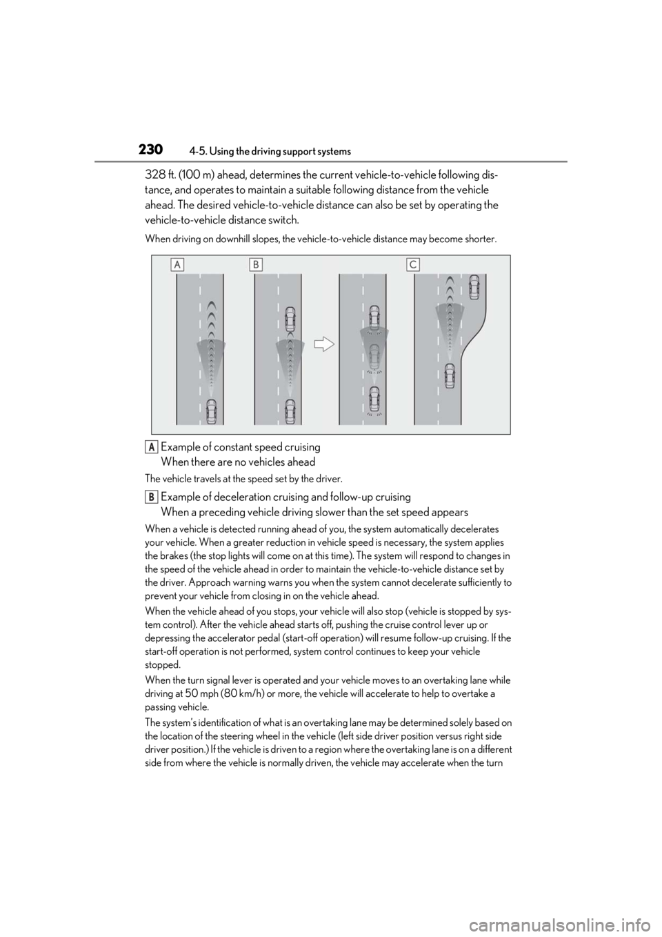
328 ft. (100 m) ahead, determines the current vehicle-to-vehicle following dis-
tance, and operates to maintain a suitab le following distance from the vehicle
ahead. The desired vehicle-to-vehicle distance can also be set by operating the
vehicle-to-vehicle distance switch.
When driving on downhill slopes, the vehicl e-to-vehicle distance may become shorter.
Example of constant speed cruising
When there are no vehicles ahead
The vehicle travels at the speed set by the driver.
Example of deceleration cruising and follow-up cruising
When a preceding vehicle driving slower than the set speed appears
When a vehicle is detected running ahead of you, the system automatically decelerates
your vehicle. When a greater reduction in vehicle speed is necessary, the system applies
the brakes (the stop lights will come on at this time). The system will respond to changes in
the speed of the vehicle ahead in order to maintain the vehicle-to-vehicle distance set by
the driver. Approach warning warns you when th e system cannot decelerate sufficiently to
prevent your vehicle from closing in on the vehicle ahead.
When the vehicle ahead of you stops, your vehi cle will also stop (vehicle is stopped by sys-
tem control). After the vehicle ahead starts off, pushing the cruise control lever up or
depressing the accelerator pedal (start-off operation) will resume follow-up cruising. If the
start-off operation is not performed, system control continues to keep your vehicle
stopped.
When the turn signal lever is operated and yo ur vehicle moves to an overtaking lane while
driving at 50 mph (80 km/h) or more, the vehicle will accelerate to help to overtake a
passing vehicle.
The system’s identification of what is an over taking lane may be determined solely based on
the location of the steering wheel in the vehicl e (left side driver position versus right side
driver position.) If the vehicle is driven to a re gion where the overtaking lane is on a different
side from where the vehicle is normally driven, the vehicle may accelerate when the turn
A
B
Page 231 of 508
2314-5. Using the driving support systems
4
Driving
signal lever is operated in the opposite direction to the overtaking lane (e.g., if the driver
normally operates the vehicle in a region where the overtaking lane is to the right but then
drives to a region where the overtaking lane is to the left, the vehicle may accelerate when
the right turn signal is activated).
Example of acceleration
When there are no longer any preceding vehicles driving slower than the set
speed
The system accelerates until the set speed is re ached. The system then returns to constant
speed cruising.
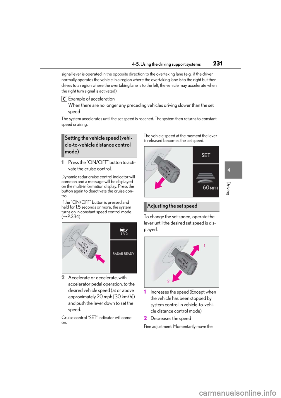
1 Press the “ON/OFF” button to acti-
vate the cruise control.
Dynamic radar cruise control indicator will
come on and a message will be displayed
on the multi-information display. Press the
button again to deactivate the cruise con-
trol.
If the “ON/OFF” button is pressed and
held for 1.5 seconds or more, the system
turns on in constant speed control mode.
( P.234)
2 Accelerate or decelerate, with
accelerator pedal operation, to the
desired vehicle speed (at or above
approximately 20 mph [30 km/h])
and push the lever down to set the
speed.
Cruise control “SET” indicator will come
on. The vehicle speed at the moment the lever
is released beco
mes the set speed.
To change the set speed, operate the
lever until the desired set speed is dis-
played.
1Increases the speed (Except when
the vehicle has been stopped by
system control in vehicle-to-vehi-
cle distance control mode)
2 Decreases the speed
Fine adjustment: Mo mentarily move the
C
Setting the vehicle speed (vehi-
cle-to-vehicle distance control
mode)
Adjusting the set speed
Page 237 of 508
2374-5. Using the driving support systems
4
Driving
Outside rear view mirror indicators
When a vehicle is detected in a blind spot
of the outside rear view mirrors or
approaching rapidly from behind into a
blind spot, the outside rear view mirror
indicator on the detected side will illumi-
nate. If the turn signal lever is operated
toward the detected side, the outside rear
view mirror indicator flashes.
BSM indicator
Illuminates when the Blind Spot Monitor is
enabled
■Outside rear view mirror indicator visi-
bility
In strong sunlight, the outside rear view mir- ror indicator may be difficult to see.
■When “Blind Spot Monitor Unavailable”
is shown on the multi-information dis-
play
Ice, snow, mud, etc., may be attached to the
rear bumper around the sensors.
( P.238) The system should return to nor-
mal operation after remo ving the ice, snow,
mud, etc. from the rear bumper. Addition-
ally, the sensors may not operate normally
when driving in extremely hot or cold envi-
ronments.
■Customization
Some functions can be customized.
( P.461)
■Certification
Except for vehicles sold in Canada
B
C
Page 339 of 508
3395-6. Using the other interior features
5
Interior features
Press the appropriate HomeLink®
button. The HomeLink
® indicator light
should turn on.
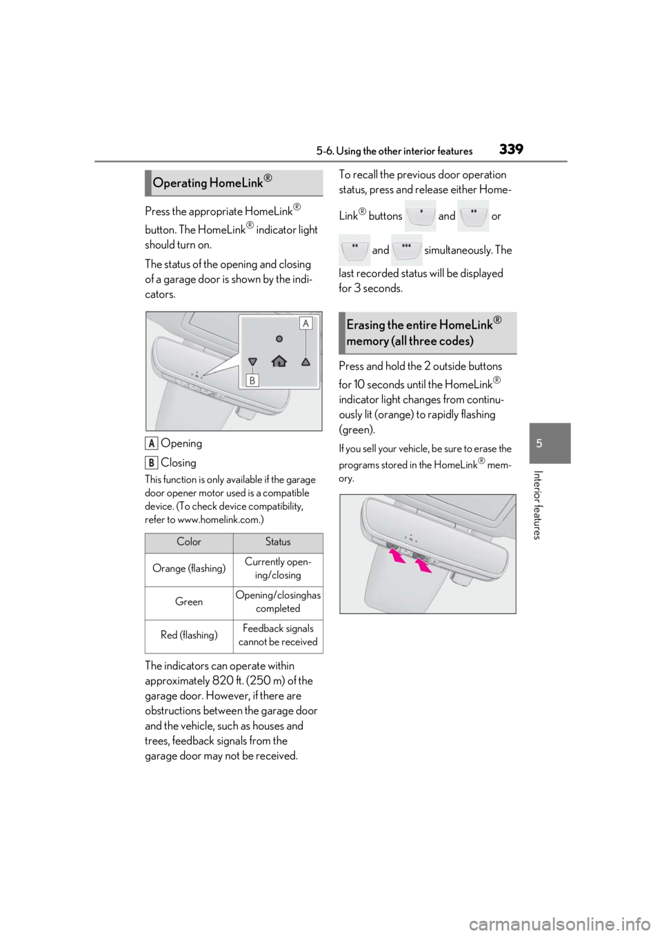
The status of the opening and closing
of a garage door is shown by the indi-
cators.
Opening
Closing
This function is only available if the garage
door opener motor used is a compatible
device. (To check device compatibility,
refer to www.homelink.com.)
The indicators can operate within
approximately 820 ft. (250 m) of the
garage door. However, if there are
obstructions between the garage door
and the vehicle, such as houses and
trees, feedback signals from the
garage door may not be received. To recall the previous door operation
status, press and release either Home-
Link
® buttons and or
and simultaneously. The
last recorded status will be displayed
for 3 seconds.
Press and hold the 2 outside buttons
for 10 seconds until the HomeLink
®
indicator light changes from continu-
ously lit (orange) to rapidly flashing
(green).
If you sell your vehicle, be sure to erase the
programs stored in the HomeLink
® mem-
ory.
Operating HomeLink®
ColorStatus
Orange (flashing)Currently open- ing/closing
GreenOpening/closing has completed
Red (flashing)Feedback signals
cannot be received
A
B
Erasing the entire HomeLink®
memory (all three codes)
Page 384 of 508
3846-3. Do-it-yourself maintenance
Check the wattage of the light bulb to
be replaced. (P.449)
P.113
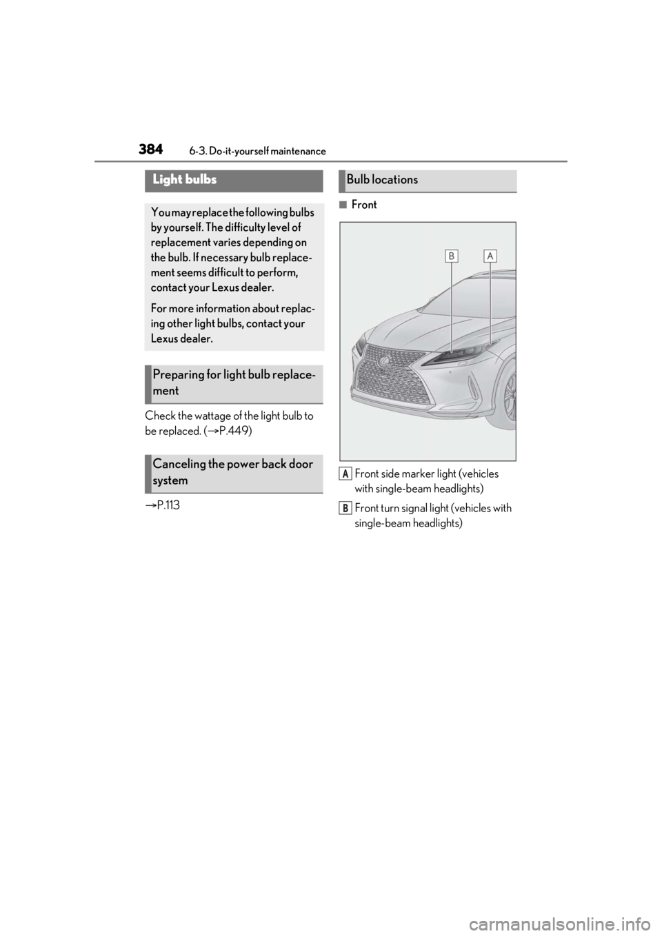
■Front
Front side marker light (vehicles
with single-beam headlights)
Front turn signal light (vehicles with
single-beam headlights)
Light bulbs
You may replace the following bulbs
by yourself. The difficulty level of
replacement varies depending on
the bulb. If necessary bulb replace-
ment seems difficult to perform,
contact your Lexus dealer.
For more information about replac-
ing other light bulbs, contact your
Lexus dealer.
Preparing for light bulb replace-
ment
Canceling the power back door
system
Bulb locations
A
B
Page 385 of 508
3856-3. Do-it-yourself maintenance
6
Maintenance and care
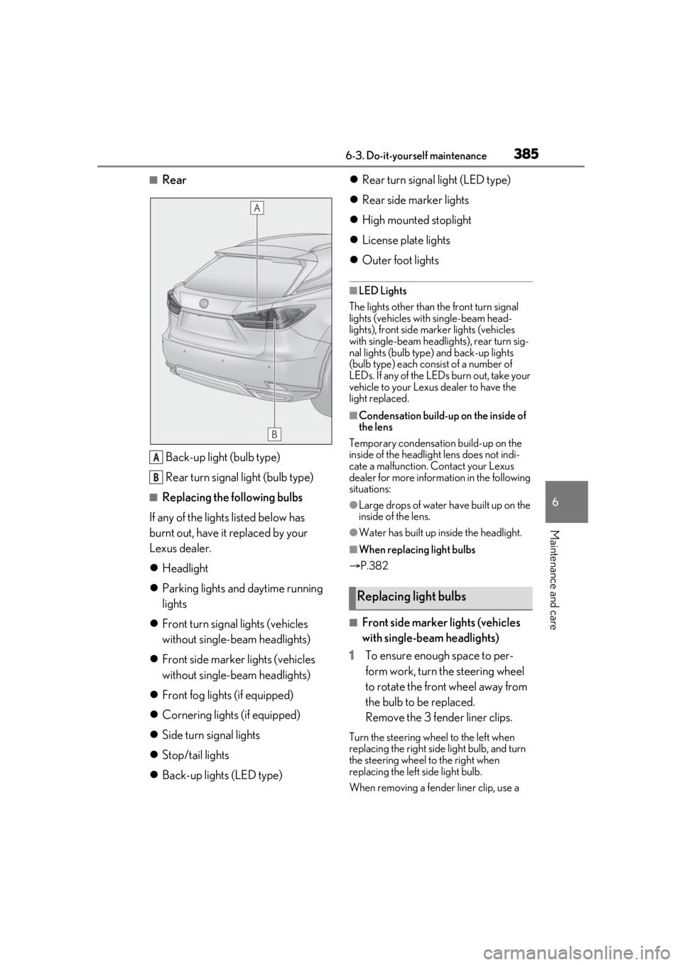
■RearBack-up light (bulb type)
Rear turn signal light (bulb type)
■Replacing the following bulbs
If any of the lights listed below has
burnt out, have it replaced by your
Lexus dealer.
Headlight
Parking lights and daytime running
lights
Front turn signal lights (vehicles
without single-beam headlights)
Front side marker lights (vehicles
without single-beam headlights)
Front fog lights (if equipped)
Cornering lights (if equipped)
Side turn signal lights
Stop/tail lights
Back-up lights (LED type)
Rear turn signal light (LED type)
Rear side marker lights
High mounted stoplight
License plate lights
Outer foot lights
■LED Lights
The lights other than the front turn signal
lights (vehicles with single-beam head-
lights), front side marker lights (vehicles
with single-beam headlig hts), rear turn sig-
nal lights (bulb type) and back-up lights
(bulb type) each consist of a number of
LEDs. If any of the LEDs burn out, take your
vehicle to your Lexus dealer to have the
light replaced.
■Condensation build-up on the inside of
the lens
Temporary condensation build-up on the
inside of the headlight lens does not indi-
cate a malfunction. Contact your Lexus
dealer for more information in the following
situations:
●Large drops of water have built up on the
inside of the lens.
●Water has built up inside the headlight.
■When replacing light bulbs
P.382
■Front side marker lights (vehicles
with single-beam headlights)
1 To ensure enough space to per-
form work, turn the steering wheel
to rotate the front wheel away from
the bulb to be replaced.
Remove the 3 fender liner clips.
Turn the steering wheel to the left when
replacing the right side light bulb, and turn
the steering wheel to the right when
replacing the left side light bulb.
When removing a fender liner clip, use a
A
B
Replacing light bulbs