LEXUS SC300 1991 Service Service Manual
Manufacturer: LEXUS, Model Year: 1991, Model line: SC300, Model: LEXUS SC300 1991Pages: 4087, PDF Size: 75.75 MB
Page 41 of 4087
R±12 AIR CONDITIONER SYSTEM RETROFIT ± AC001±98 April 3, 1998
Page 4 of 4
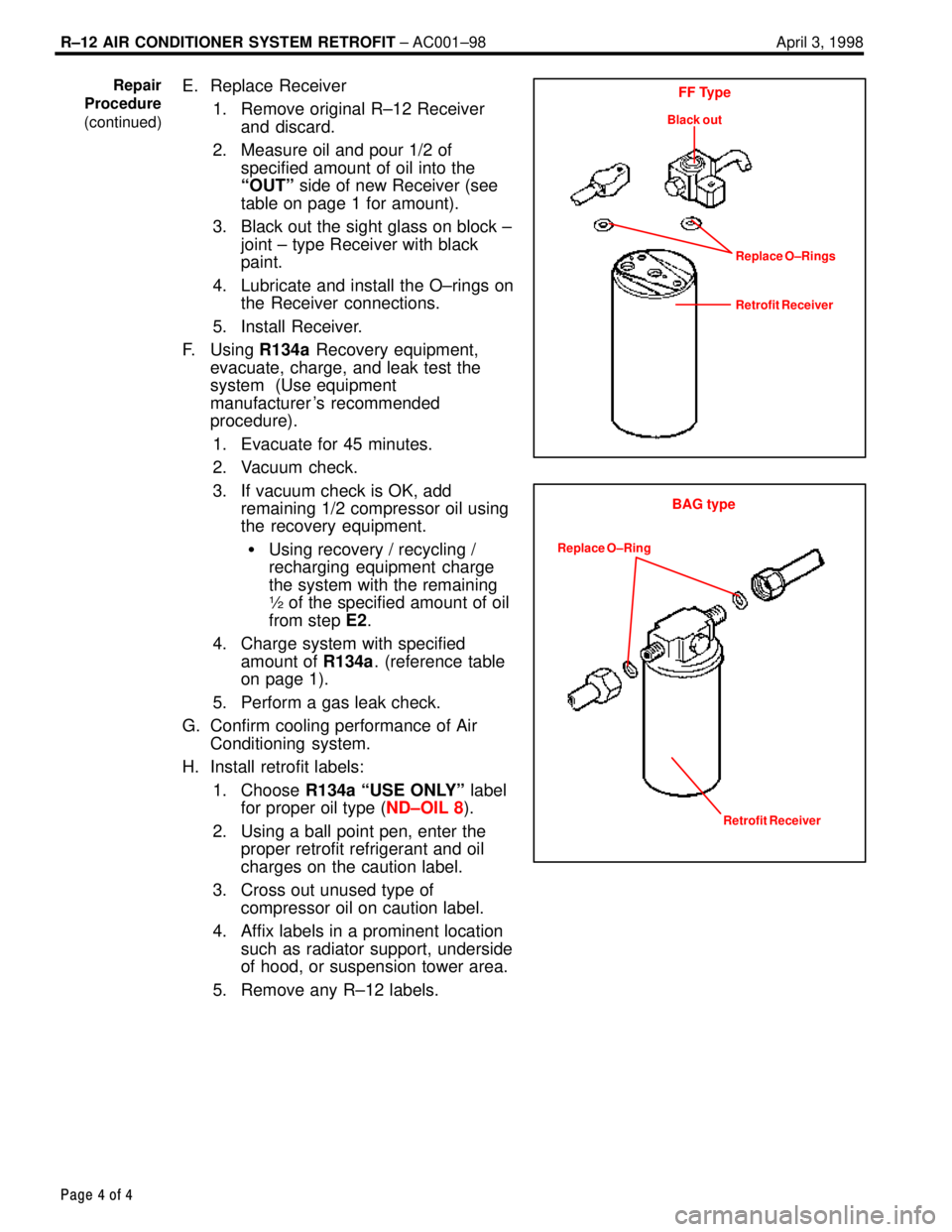
E. Replace Receiver
1. Remove original R±12 Receiverand discard.
2. Measure oil and pour 1/2 of specified amount of oil into the
ªOUTº side of new Receiver (see
table on page 1 for amount).
3. Black out the sight glass on block ± joint ± type Receiver with black
paint.
4. Lubricate and install the O±rings on the Receiver connections.
5. Install Receiver.
F. Using R134a Recovery equipment,
evacuate, charge, and leak test the
system (Use equipment
manufacturer 's recommended
procedure).
1. Evacuate for 45 minutes.
2. Vacuum check.
3. If vacuum check is OK, add remaining 1/2 compressor oil using
the recovery equipment.
� Using recovery / recycling /
recharging equipment charge
the system with the remaining
½ of the specified amount of oil
from step E2.
4. Charge system with specified amount of R134a. (reference table
on page 1).
5. Perform a gas leak check.
G. Confirm cooling performance of Air Conditioning system.
H. Install retrofit labels:
1. Choose R134a ªUSE ONLYº label
for proper oil type ( ND±OIL 8).
2. Using a ball point pen, enter the proper retrofit refrigerant and oil
charges on the caution label.
3. Cross out unused type of compressor oil on caution label.
4. Affix labels in a prominent location such as radiator support, underside
of hood, or suspension tower area.
5. Remove any R±12 labels.Repair
Procedure
(continued)FF Type
Black out
Replace O±Rings
Retrofit Receiver
BAG type
Replace O±Ring
Retrofit Receiver
WhereEverybodyKnowsYourName
Page 42 of 4087

AIR CONDITIONING
SYSTEM
±
AIR CONDITIONING SYSTEMAC±1
WhereEverybodyKnowsYourName
Page 43 of 4087
GENERAL DESCRIPTION
REFRIGERATION SYSTEM
Prevention of Refrigerant Release and
Excessive Quantities
Refrigerant (CFCs) for automobile air conditioners is be-
lieved to cause harm by depleting the ozone layer which
helps to protect us from the ultraviolet rays of the sun.
Therefore, it is necessary to prevent release of refrigerant to
the atmosphere and to use minimum amount when servicing
the air conditioner.
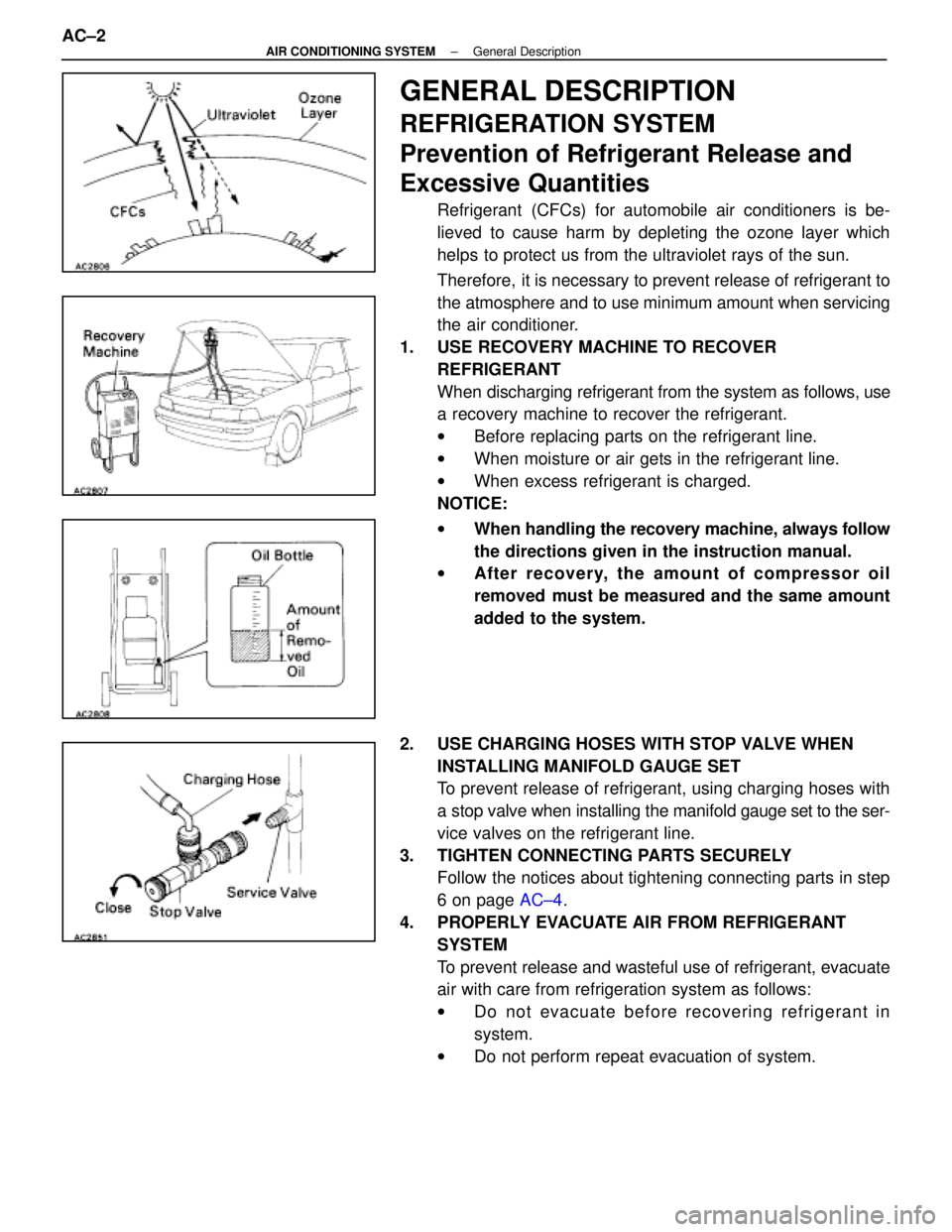
1. USE RECOVERY MACHINE TO RECOVER REFRIGERANT
When discharging refrigerant from the system as follows, use
a recovery machine to recover the refrigerant.
wBefore replacing parts on the refrigerant line.
w When moisture or air gets in the refrigerant line.
w When excess refrigerant is charged.
NOTICE:
w When handling the recovery machine, always follow
the directions given in the instruction manual.
w After recovery, the amount of compr essor oil
removed must be measured and the same amount
added to the system.
2. USE CHARGING HOSES WITH STOP VALVE WHEN INSTALLING MANIFOLD GAUGE SET
To prevent release of refrigerant, using charging hoses with
a stop valve when installing the manifold gauge set to the ser-
vice valves on the refrigerant line.
3. TIGHTEN CONNECTING PARTS SECURELY Follow the notices about tightening connecting parts in step
6 on page AC±4.
4. PROPERLY EVACUATE AIR FROM REFRIGERANT SYSTEM
To prevent release and wasteful use of refrigerant, evacuate
air with care from refrigeration system as follows:
wDo not evacuate before recovering refrigerant in
system.
w Do not perform repeat evacuation of system.
AC±2
±
AIR CONDITIONING SYSTEM General Description
WhereEverybodyKnowsYourName
Page 44 of 4087
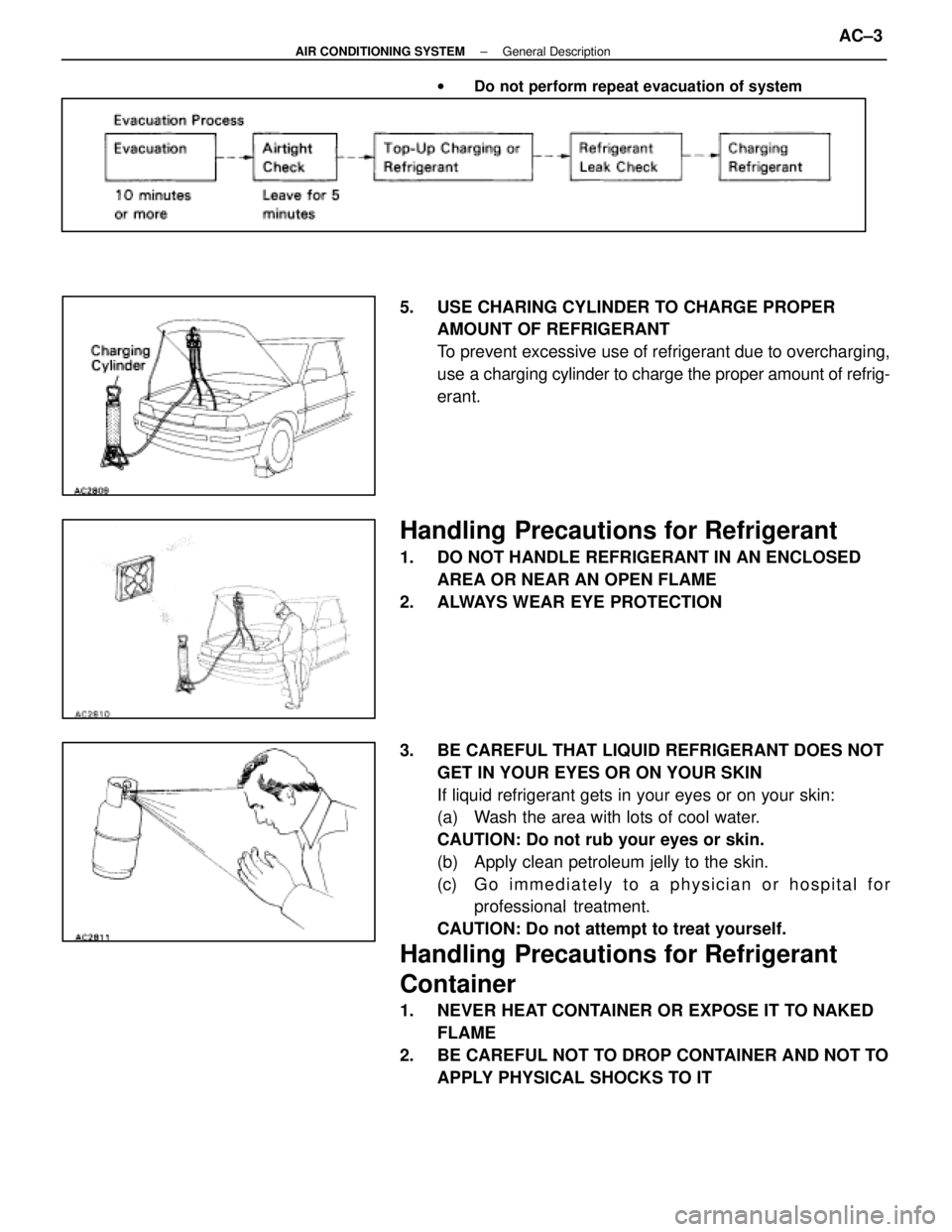
wDo not perform repeat evacuation of system
5. USE CHARING CYLINDER TO CHARGE PROPER
AMOUNT OF REFRIGERANT
To prevent excessive use of refrigerant due to overcharging,
use a charging cylinder to charge the proper amount of refrig-
erant.
Handling Precautions for Refrigerant
1. DO NOT HANDLE REFRIGERANT IN AN ENCLOSED
AREA OR NEAR AN OPEN FLAME
2. ALWAYS WEAR EYE PROTECTION
3. BE CAREFUL THAT LIQUID REFRIGERANT DOES NOT GET IN YOUR EYES OR ON YOUR SKIN
If liquid refrigerant gets in your eyes or on your skin:
(a) Wash the area with lots of cool water.
CAUTION: Do not rub your eyes or skin.
(b) Apply clean petroleum jelly to the skin.
(c) G o i m m e d i a t e l y t o a p h y s i c i a n o r h o s p i t a l f o rprofessional treatment.
CAUTION: Do not attempt to treat yourself.
Handling Precautions for Refrigerant
Container
1. NEVER HEAT CONTAINER OR EXPOSE IT TO NAKED FLAME
2. BE CAREFUL NOT TO DROP CONTAINER AND NOT TO APPLY PHYSICAL SHOCKS TO IT
±
AIR CONDITIONING SYSTEM General DescriptionAC±3
WhereEverybodyKnowsYourName
Page 45 of 4087
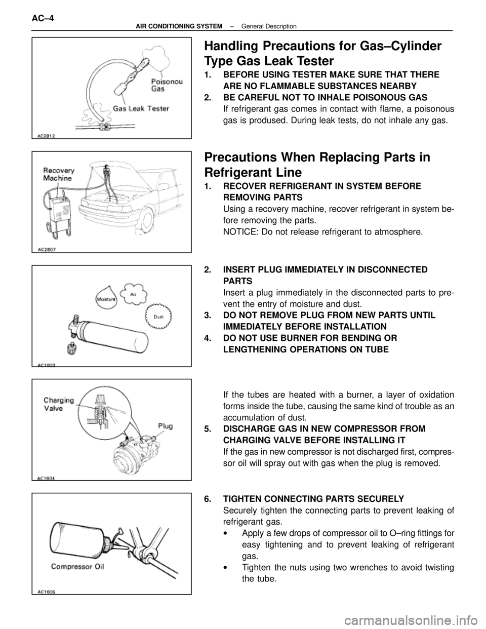
Handling Precautions for Gas±Cylinder
Type Gas Leak Tester
1. BEFORE USING TESTER MAKE SURE THAT THEREARE NO FLAMMABLE SUBSTANCES NEARBY
2. BE CAREFUL NOT TO INHALE POISONOUS GAS If refrigerant gas comes in contact with flame, a poisonous
gas is prodused. During leak tests, do not inhale any gas.
Precautions When Replacing Parts in
Refrigerant Line
1. RECOVER REFRIGERANT IN SYSTEM BEFOREREMOVING PARTS
Using a recovery machine, recover refrigerant in system be-
fore removing the parts.
NOTICE: Do not release refrigerant to atmosphere.
2. INSERT PLUG IMMEDIATELY IN DISCONNECTED PARTS
Insert a plug immediately in the disconnected parts to pre-
vent the entry of moisture and dust.
3. DO NOT REMOVE PLUG FROM NEW PARTS UNTIL
IMMEDIATELY BEFORE INSTALLATION
4. DO NOT USE BURNER FOR BENDING OR LENGTHENING OPERATIONS ON TUBE
If the tubes are heated with a burner, a layer of oxidation
forms inside the tube, causing the same kind of trouble as an
accumulation of dust.
5. DISCHARGE GAS IN NEW COMPRESSOR FROM
CHARGING VALVE BEFORE INSTALLING IT
If the gas in new compressor is not discharged first, compres-
sor oil will spray out with gas when the plug is removed.
6. TIGHTEN CONNECTING PARTS SECURELY Securely tighten the connecting parts to prevent leaking of
refrigerant gas.
wApply a few drops of compressor oil to O±ring fittings for
easy tightening and to prevent leaking of refrigerant
gas.
w Tighten the nuts using two wrenches to avoid twisting
the tube.
AC±4
±
AIR CONDITIONING SYSTEM General Description
WhereEverybodyKnowsYourName
Page 46 of 4087
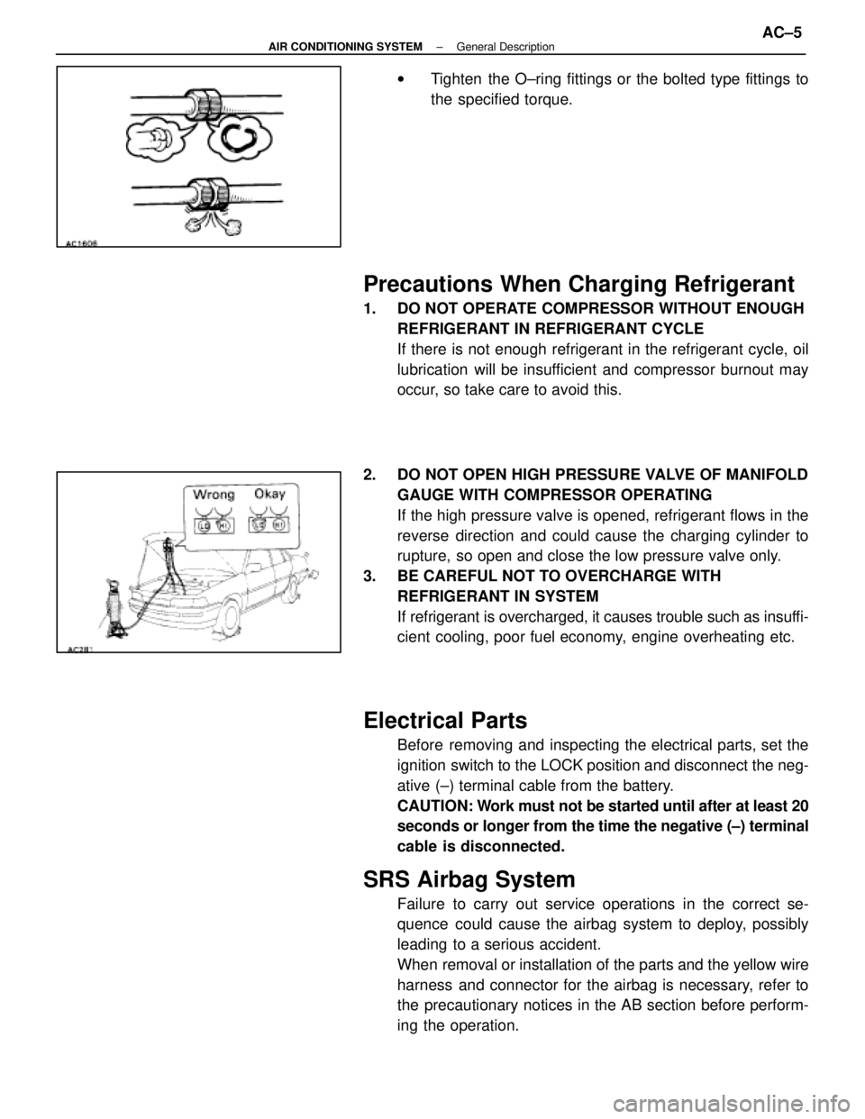
wTighten the O±ring fittings or the bolted type fittings to
the specified torque.
Precautions When Charging Refrigerant
1. DO NOT OPERATE COMPRESSOR WITHOUT ENOUGH
REFRIGERANT IN REFRIGERANT CYCLE
If there is not enough refrigerant in the refrigerant cycle, oil
lubrication will be insufficient and compressor burnout may
occur, so take care to avoid this.
2. DO NOT OPEN HIGH PRESSURE VALVE OF MANIFOLD GAUGE WITH COMPRESSOR OPERATING
If the high pressure valve is opened, refrigerant flows in the
reverse direction and could cause the charging cylinder to
rupture, so open and close the low pressure valve only.
3. BE CAREFUL NOT TO OVERCHARGE WITH REFRIGERANT IN SYSTEM
If refrigerant is overcharged, it causes trouble such as insuffi-
cient cooling, poor fuel economy, engine overheating etc.
Electrical Parts
Before removing and inspecting the electrical parts, set the
ignition switch to the LOCK position and disconnect the neg-
ative (±) terminal cable from the battery.
CAUTION: Work must not be started until after at least 20
seconds or longer from the time the negative (±) terminal
cable is disconnected.
SRS Airbag System
Failure to carry out service operations in the correct se-
quence could cause the airbag system to deploy, possibly
leading to a serious accident.
When removal or installation of the parts and the yellow wire
harness and connector for the airbag is necessary, refer to
the precautionary notices in the AB section before perform-
ing the operation.
±
AIR CONDITIONING SYSTEM General DescriptionAC±5
WhereEverybodyKnowsYourName
Page 47 of 4087
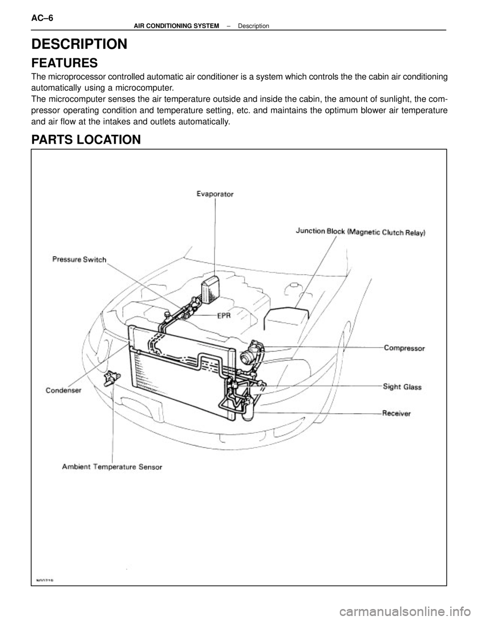
DESCRIPTION
FEATURES
The microprocessor controlled automatic air conditioner is a system whic\
h controls the the cabin air conditioning
automatically using a microcomputer.
The microcomputer senses the air temperature outside and inside the cabin, \
the amount of sunlight, the com-
pressor operating condition and temperature setting, etc. and maintains the optimum blower\
air temperature
and air flow at the intakes and outlets automatically.
PARTS LOCATION
AC±6±
AIR CONDITIONING SYSTEM Description
WhereEverybodyKnowsYourName
Page 48 of 4087

PARTS LOCATION (Cont'd)
±
AIR CONDITIONING SYSTEM DescriptionAC±7
WhereEverybodyKnowsYourName
Page 49 of 4087
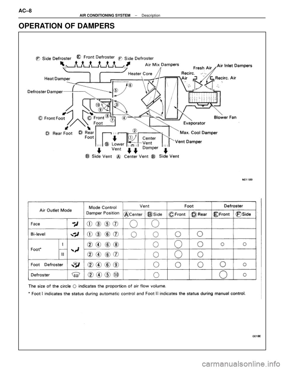
OPERATION OF DAMPERS
AC±8±
AIR CONDITIONING SYSTEM Description
WhereEverybodyKnowsYourName
Page 50 of 4087

CONTROL FUNCTIONS
Interior Room Temperature Control System
(a) The desired temperature is set using the TEMP switch.
(b) From the input signals (room temperature sensor, ambient temperature sensor, evaporator temperaturesensor and solar sensor) and the temperature setting, the air conditioner con\
trol ECU determines the air
flow volume and outputs signals to the air mix servomotor.
(c) When it receives signals from the ECU, the air mix servomotor opens or close\
s the air mix damper to change the air flow temperature. When the temperature reaches the specified te\
mperature, it is detected
by the air mix damper position sensor and the ECU stops the servomotor.
HINT: If the desired temperature setting is 65 °F, the ECU forcedly sets the air mix damper to the Max Cool posi-
tion. If it is set at 85 °F, the ECU forcedly sets the air mix damper to the Max Hot position.
±
AIR CONDITIONING SYSTEM DescriptionAC±9
WhereEverybodyKnowsYourName