LEXUS SC300 1991 Service Service Manual
SC300 1991
LEXUS
LEXUS
https://www.carmanualsonline.info/img/36/57052/w960_57052-0.png
LEXUS SC300 1991 Service Service Manual
Page 350 of 4087
AT±66
IN±33
WIRING DIAGRAM
Pattern Select Switch Circuit
CIRCUIT DESCRIPTION
The ECM memory contains the shift programs for the NORMAL and POWER pattern\
s, 2 position and L
position and the lock±up patterns. Following the programs corresponding to the\
signals from the pattern
select switch, the park/neutral position switch and other various sensor\
s the ECM switches the solenoid
valves ON and OFF, thereby controlling the transmission gear change and the lock±up cl\
utch operation.
DIAGNOSTIC CHARTDIAGNOSTIC CHART
AT±110±
A304E (1UZ±FE) AUTOMATIC TRANSMISSION TROUBLESHOOTING
WhereEverybodyKnowsYourName
Page 352 of 4087
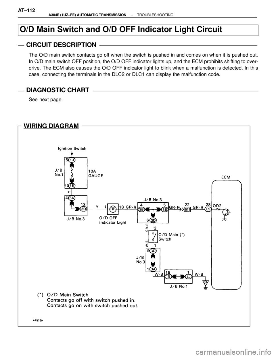
WIRING DIAGRAM
O/D Main Switch and O/D OFF Indicator Light Circuit
CIRCUIT DESCRIPTION
The O/D main switch contacts go off when the switch is pushed in and comes on when it is pushed out.
In O/D main switch OFF position, the O/D OFF indicator lights up, and the \
ECM prohibits shifting to over-
drive. The ECM also causes the O/D OFF indicator light to blink when a malfunc\
tion is detected. In this
case, connecting the terminals in the DLC2 or DLC1 can display the malfu\
nction code.
DIAGNOSTIC CHARTDIAGNOSTIC CHART
See next page.
AT±112
±
A304E (1UZ±FE) AUTOMATIC TRANSMISSION TROUBLESHOOTING
WhereEverybodyKnowsYourName
Page 356 of 4087
AT±66
IN±33
WIRING DIAGRAM
O/D Cancel Signal Circuit
CIRCUIT DESCRIPTION
While driving with cruise control activated, in order to minimize gear shifti\
ng and provide smooth cruising
when driving uphill, overdrive may be prohibited temporarily in some conditions.The cruise control ECU
sends O/D cut signals to the ECM as necessary and the ECM cancels overdrive s\
hifting until these signals
are discontinued.(For details, see the cruise control system, on BE sectio\
n).
DIAGNOSTIC CHARTDIAGNOSTIC CHART
AT±116±
A304E (1UZ±FE) AUTOMATIC TRANSMISSION TROUBLESHOOTING
WhereEverybodyKnowsYourName
Page 358 of 4087
AT±66
IN±33
WIRING DIAGRAM
TE1 Terminal Circuit
CIRCUIT DESCRIPTION
ECM displays diagnostic trouble codes using the O/D OFF indicator light \
when terminals TE and E of the
DLC2 or DLC1 are connected.
DIAGNOSTIC CHARTDIAGNOSTIC CHART
AT±118±
A304E (1UZ±FE) AUTOMATIC TRANSMISSION TROUBLESHOOTING
WhereEverybodyKnowsYourName
Page 360 of 4087
IN±33
WIRING DIAGRAM
TT Terminal Circuit
CIRCUIT DESCRIPTION
Checks of ECM input and output signals related to the throttle position sensor\
brakes, shift position and
other circuits can be performed by measuring the voltages at terminal T
T of the DLC1.
DIAGNOSTIC CHARTDIAGNOSTIC CHART
AT±120±
A304E (1UZ±FE) AUTOMATIC TRANSMISSION TROUBLESHOOTING
WhereEverybodyKnowsYourName
Page 372 of 4087
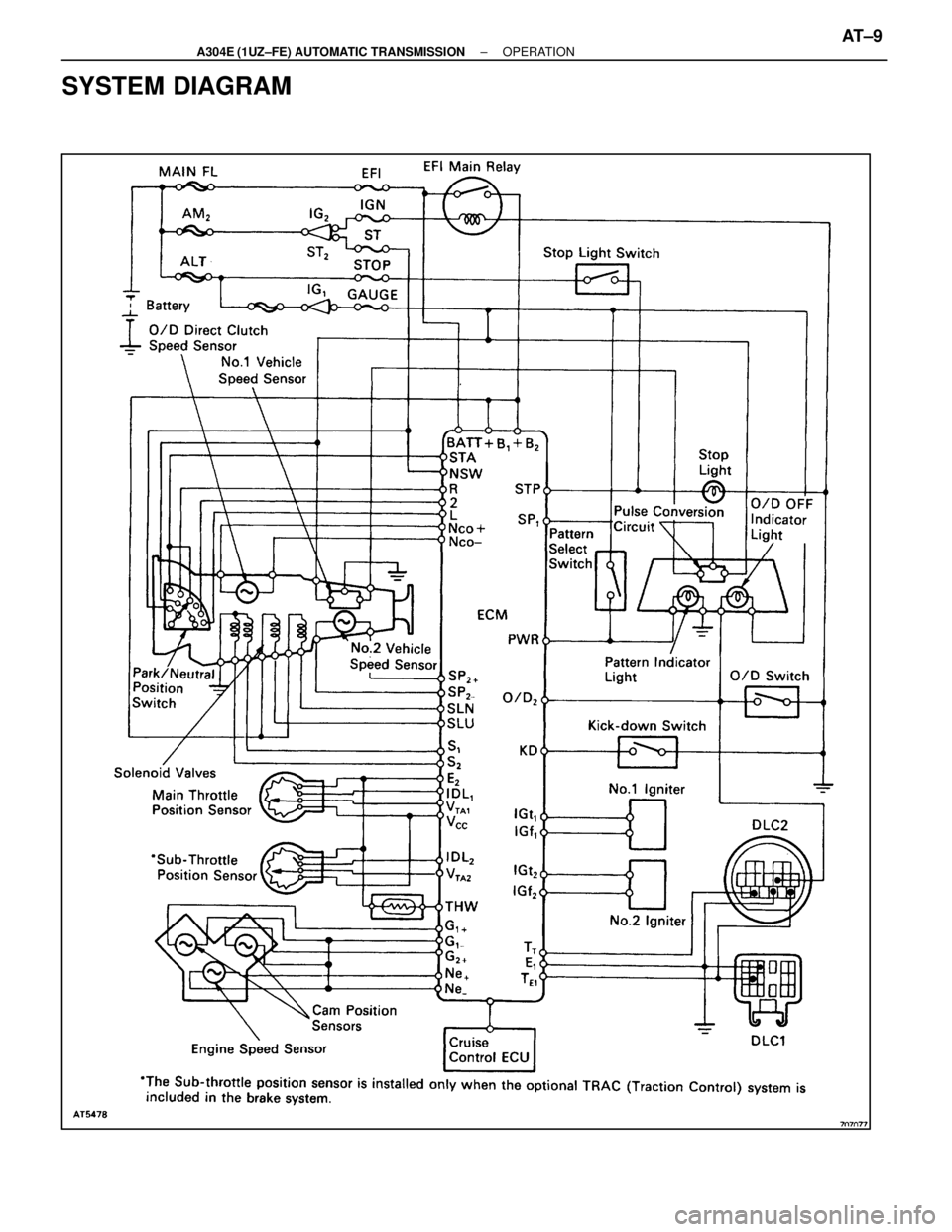
SYSTEM DIAGRAM
±
A304E (1UZ±FE) AUTOMATIC TRANSMISSION OPERATIONAT±9
WhereEverybodyKnowsYourName
Page 482 of 4087
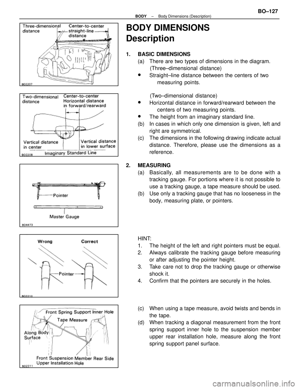
BODY DIMENSIONS
Description
1. BASIC DIMENSIONS(a) There are two types of dimensions in the diagram. (Three±dimensional distance)
wStraight±line distance between the centers of two
measuring points.
(Two±dimensional distance)
wHorizontal distance in forward/rearward between the centers of two measuring points.
wThe height from an imaginary standard line.
(b) In cases in which only one dimension is given, left and right are symmetrical.
(c) The dimensions in the following drawing indicate actual
distance. Therefore, please use the dimensions as a
reference.
2. MEASURING (a) Basically, all measurements are to be done with atracking gauge. For portions where it is not possible to
use a tracking gauge, a tape measure should be used.
(b) Use only a tracking gauge that has no looseness in the body, measuring plate, or pointers.
HINT:
1. The height of the left and right pointers must be equal.
2. Always calibrate the tracking gauge before measuring or after adjusting the pointer height.
3. Take care not to drop the tracking gauge or otherwise shock it.
4. Confirm that the pointers are securely in the holes.
(c) When using a tape measure, avoid twists and bends in
the tape.
(d) When tracking a diagonal measurement from the front
spring support inner hole to the suspension member
upper rear installation hole, measure along the front
spring support panel surface.
±
BODY Body Dimensions (Description)BO±127
WhereEverybodyKnowsYourName
Page 500 of 4087
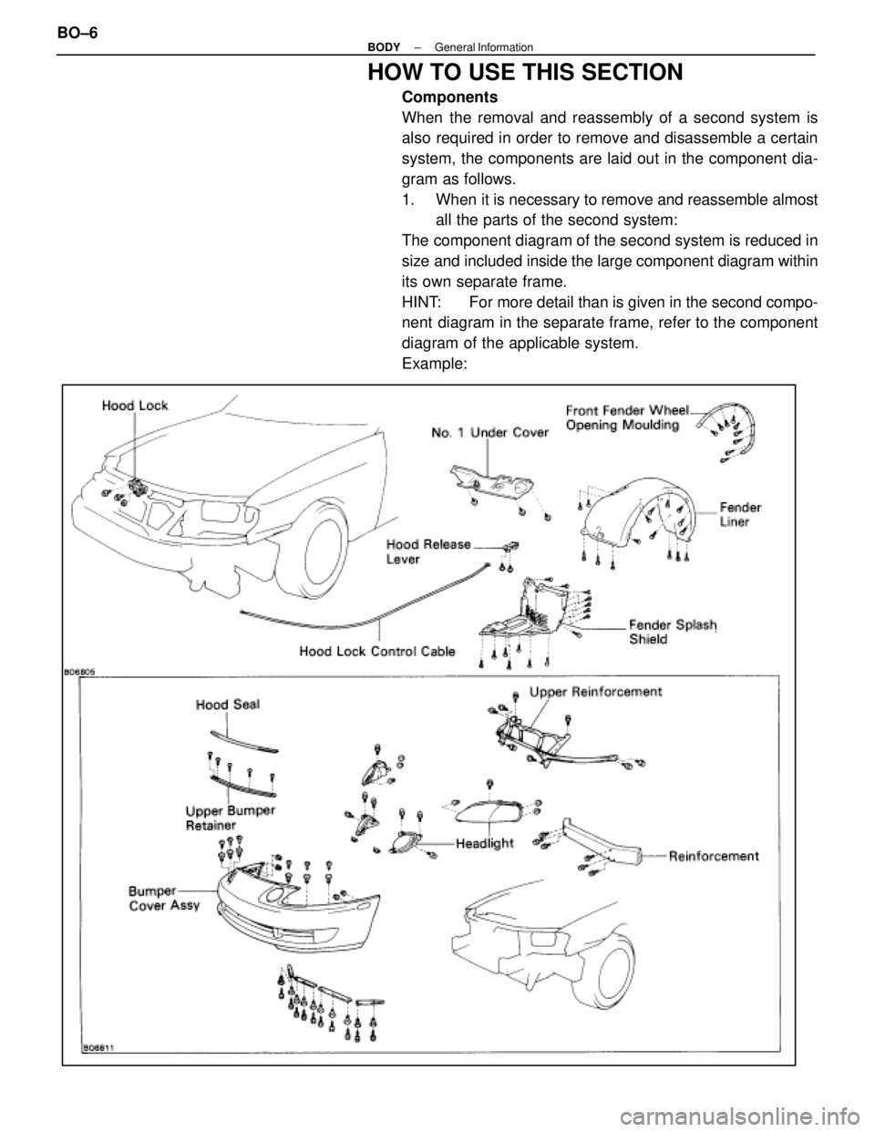
HOW TO USE THIS SECTION
Components
When the removal and reassembly of a second system is
also required in order to remove and disassemble a certain
system, the components are laid out in the component dia-
gram as follows.
1. When it is necessary to remove and reassemble almostall the parts of the second system:
The component diagram of the second system is reduced in
size and included inside the large component diagram within
its own separate frame.
HINT: For more detail than is given in the second compo-
nent diagram in the separate frame, refer to the component
diagram of the applicable system.
Example:
BO±6
±
BODY General Information
WhereEverybodyKnowsYourName
Page 501 of 4087
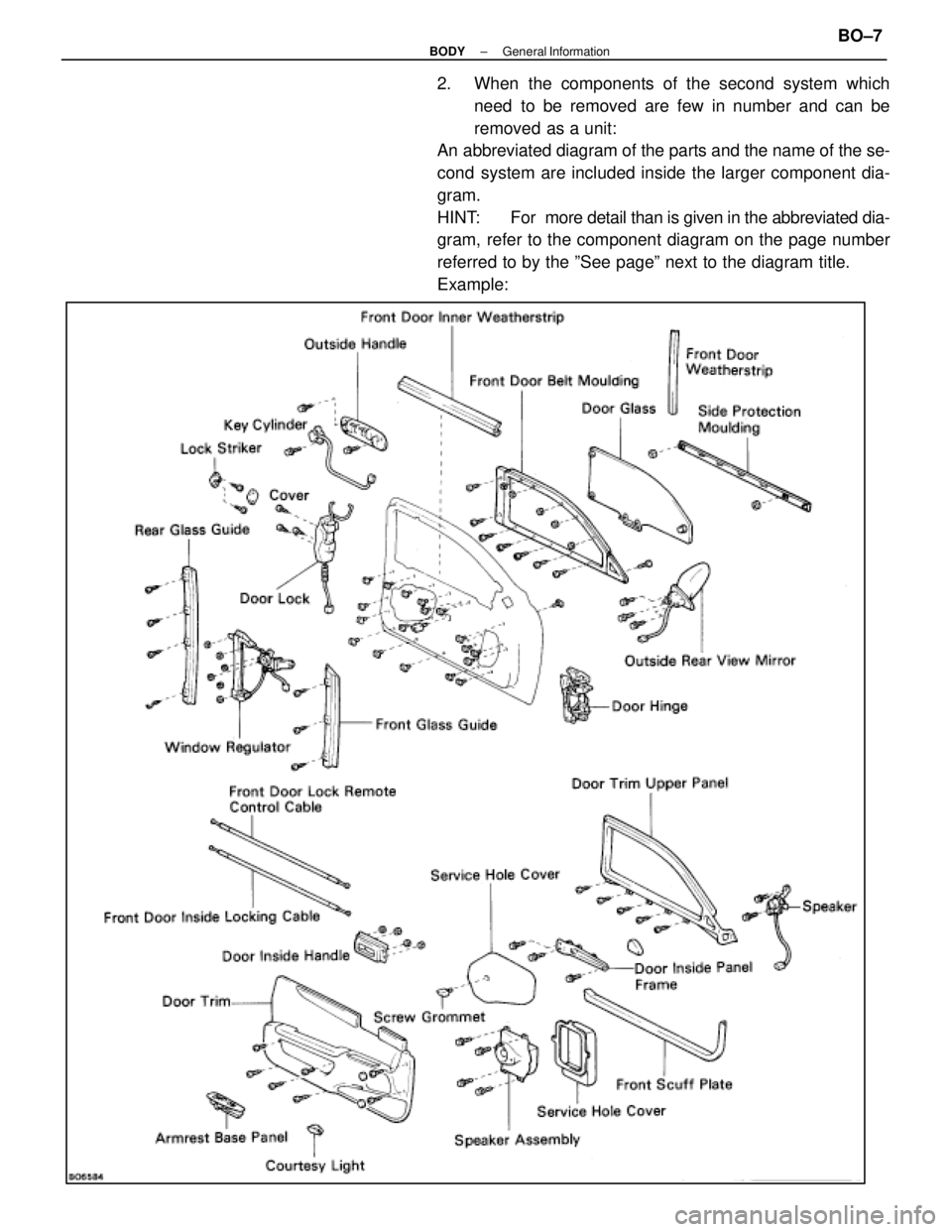
2. When the components of the second system whichneed to be removed are few in number and can be
removed as a unit:
An abbreviated diagram of the parts and the name of the se-
cond system are included inside the larger component dia-
gram.
HINT: For more detail than is given in the abbreviated dia-
gram, refer to the component diagram on the page number
referred to by the ºSee pageº next to the diagram title.
Example:
±
BODY General InformationBO±7
WhereEverybodyKnowsYourName
Page 540 of 4087
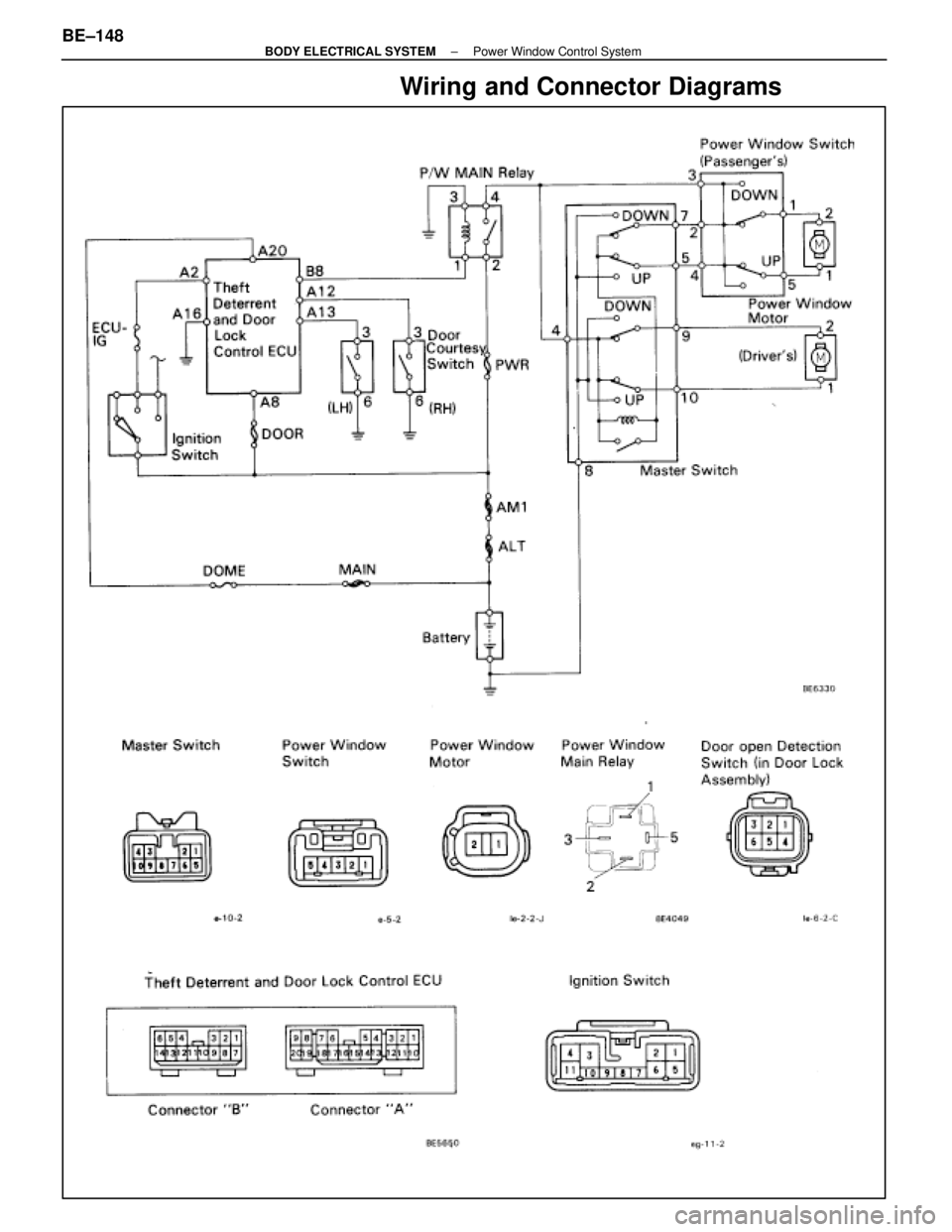
Wiring and Connector Diagrams
BE±148±
BODY ELECTRICAL SYSTEM Power Window Control System
WhereEverybodyKnowsYourName