turn LEXUS SC300 1991 Service Repair Manual
[x] Cancel search | Manufacturer: LEXUS, Model Year: 1991, Model line: SC300, Model: LEXUS SC300 1991Pages: 4087, PDF Size: 75.75 MB
Page 7 of 4087
IDENTIFICATION INFORMATION
VEHICLE IDENTIFICATION NUMBER
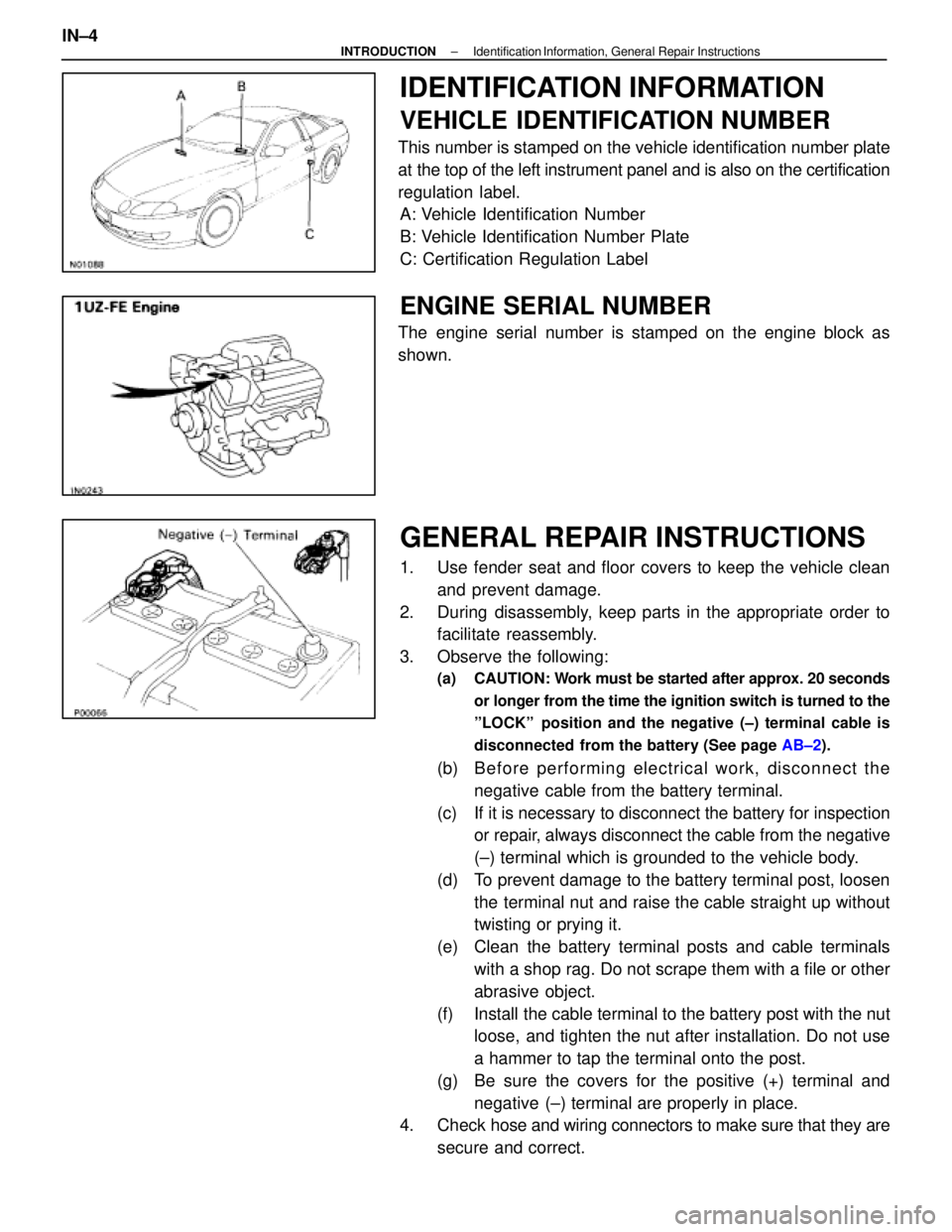
This number is stamped on the vehicle identification number plate
at the top of the left instrument panel and is also on the certification
regulation label.A: Vehicle Identification Number
B: Vehicle Identification Number Plate
C: Certification Regulation Label
ENGINE SERIAL NUMBER
The engine serial number is stamped on the engine block as
shown.
GENERAL REPAIR INSTRUCTIONS
1. Use fender seat and floor covers to keep the vehicle clean
and prevent damage.
2. During disassembly, keep parts in the appropriate order to facilitate reassembly.
3. Observe the following:
(a) CAUTION: W ork must be started after approx. 20 seconds
or longer from the time the ignition switch is turned to the
ºLOCKº position and the negative (±) terminal cable is
disconnected from the battery (See page AB±2).
(b) B e fo re pe rfo rmin g ele ctrica l wo rk, disc onnect the
negative cable from the battery terminal.
(c) If it is necessary to disconnect the battery for inspection or repair, always disconnect the cable from the negative
(±) terminal which is grounded to the vehicle body.
(d) To prevent damage to the battery terminal post, loosen the terminal nut and raise the cable straight up without
twisting or prying it.
(e) Clean the battery terminal posts and cable terminals with a shop rag. Do not scrape them with a file or other
abrasive object.
(f) Install the cable terminal to the battery post with the nut loose, and tighten the nut after installation. Do not use
a hammer to tap the terminal onto the post.
(g) Be sure the covers for the positive (+) terminal and negative (±) terminal are properly in place.
4. Check hose and wiring connectors to make sure that they are
secure and correct.
IN±4
±
INTRODUCTION Identification Information, General Repair Instructions
WhereEverybodyKnowsYourName
Page 9 of 4087
12. Observe the following precautions to avoid damage to theparts:
(a) Do not open the cover or case of the ECU unless
absolutely necessary (If the IC terminals are touched, the
IC may be destroyed by static electricity.).
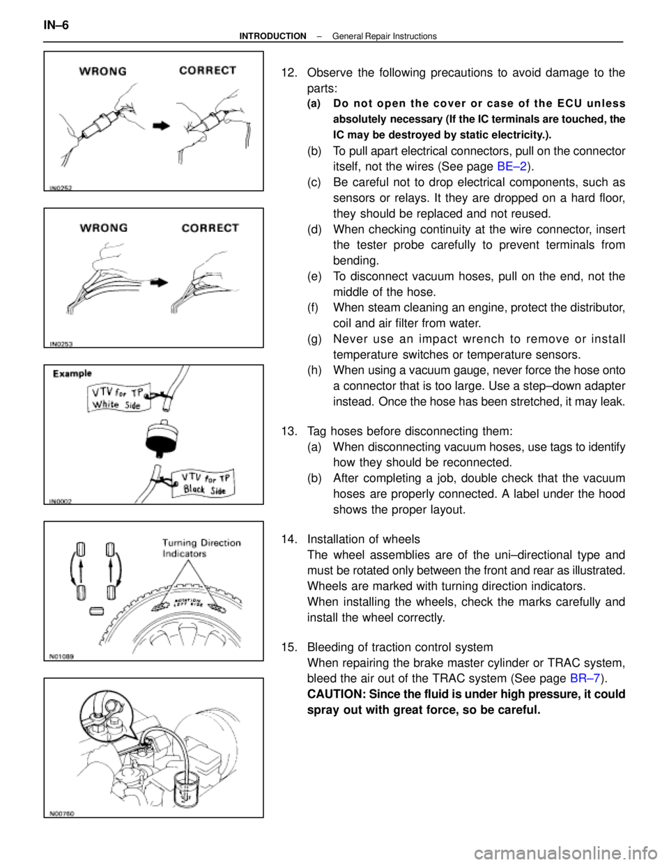
(b) To pull apart electrical connectors, pull on the connectoritself, not the wires (See page BE±2).
(c) Be careful not to drop electrical components, such as sensors or relays. It they are dropped on a hard floor,
they should be replaced and not reused.
(d) When checking continuity at the wire connector, insert the tester probe carefully to prevent terminals from
bending.
(e) To disconnect vacuum hoses, pull on the end, not the middle of the hose.
(f) When steam cleaning an engine, protect the distributor,
coil and air filter from water.
(g) Ne ve r use an imp a ct wre n ch to re mo ve or in sta ll temperature switches or temperature sensors.
(h) When using a vacuum gauge, never force the hose onto
a connector that is too large. Use a step±down adapter
instead. Once the hose has been stretched, it may leak.
13. Tag hoses before disconnecting them: (a) When disconnecting vacuum hoses, use tags to identify
how they should be reconnected.
(b) After completing a job, double check that the vacuum hoses are properly connected. A label under the hood
shows the proper layout.
14. Installation of wheels The wheel assemblies are of the uni±directional type and
must be rotated only between the front and rear as illustrated.
Wheels are marked with turning direction indicators.
When installing the wheels, check the marks carefully and
install the wheel correctly.
15. Bleeding of traction control system When repairing the brake master cylinder or TRAC system,
bleed the air out of the TRAC system (See page BR±7).
CAUTION: Since the fluid is under high pressure, it could
spray out with great force, so be careful.
IN±6
±
INTRODUCTION General Repair Instructions
WhereEverybodyKnowsYourName
Page 11 of 4087
PRECAUTIONS FOR VEHICLES
EQUIPPED WITH SRS AIRBAG
The LEXUS SC400 is equipped with an SRS (Supplemental Re-
straint System) airbag.
Failure to carry out service operations in the correct sequence
could cause the airbag system to unexpectedly deploy during serv-
icing, possibly leading to a serious accident.
Further, if a mistake is made in servicing the airbag system, it is pos-
sible the airbag may fail to operate when required.
Before performing servicing (including removal or installation of
parts, inspection or replacement), be sure to read the following
items carefully, then follow the correct procedure described in this
manual.
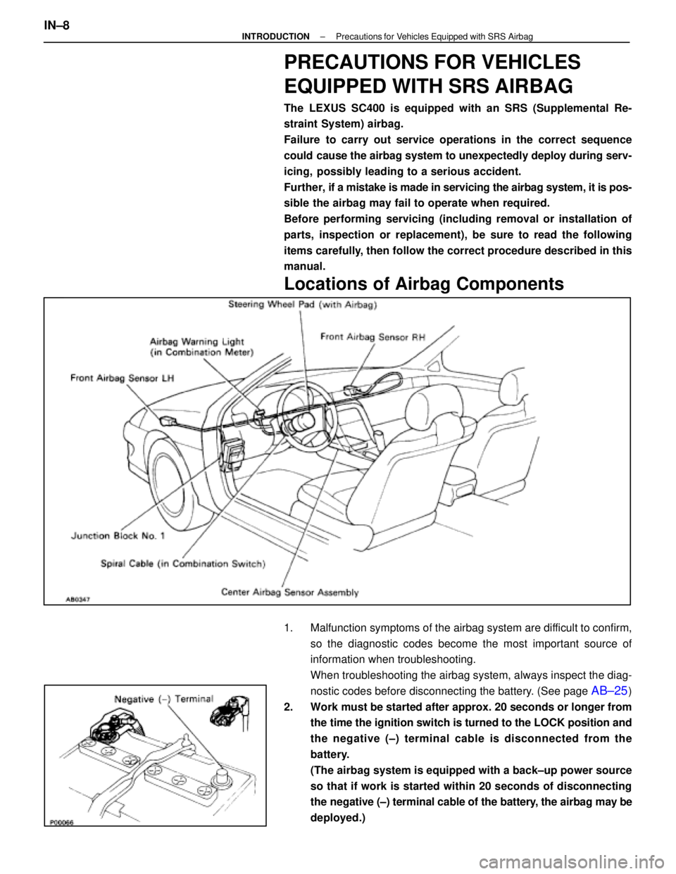
Locations of Airbag Components
1. Malfunction symptoms of the airbag system are difficult to confirm,
so the diagnostic codes become the most important source of
information when troubleshooting.
When troubleshooting the airbag system, always inspect the diag-
nostic codes before disconnecting the battery. (See page
AB±25)
2. Work must be started after approx. 20 seconds or longer from the time the ignition switch is turned to the LOCK position and
the negative (±) terminal cable is disconnected from the
battery.
(The airbag system is equipped with a back±up power source
so that if work is started within 20 seconds of disconnecting
the negative (±) terminal cable of the battery, the airbag may be
deployed.)
IN±8±
INTRODUCTION Precautions for Vehicles Equipped with SRS Airbag
WhereEverybodyKnowsYourName
Page 15 of 4087

PRECAUTIONS FOR VEHICLES
EQUIPPED WITH A CATALYTIC
CONVERTER
CAUTION: If large amounts of unburned gasoline flow into the
converter, it may overheat and create a fire hazard. To prevent
this, observe the following precautions and explain them to
your customer.
1. Use only unleaded gasoline.
2. Avoid prolonged idling. Avoid running the engine at idle speed for more than 20 min-
utes.
3. Avoid spark jump test. (a) P e r f o r m s p a r k j u m p t e s t o n l y w h e n a b s o l u t e l ynecessary. Perform this test as rapidly as possible.
(b) While testing, never race the engine.
4. Avoid prolonged engine compression measurement.
Engine compression tests must be done as rapidly as pos-
sible.
5. Do not run engine when fuel tank is nearly empty. This may c ause the engine to misfire and create an extra load
on the converter.
6. Avoid coasting with ignition turned off and prolonged braking.
7. Do not dispose of used catalyst along with parts contaminated with gasoline or oil.
IN±12
±
INTRODUCTION Precautions for Vehicles Equipped with a Catalytic
Converter
WhereEverybodyKnowsYourName
Page 16 of 4087
PRECAUTIONS FOR VEHICLES
EQUIPPED WITH TRACTION
CONTROL (TRAC) SYSTEM
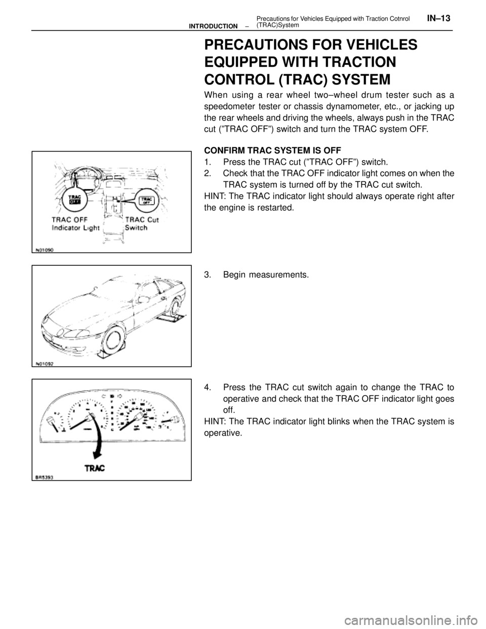
When using a rear wheel two±wheel drum tester such as a
speedometer tester or chassis dynamometer, etc., or jacking up
the rear wheels and driving the wheels, always push in the TRAC
cut (ºTRAC OFFº) switch and turn the TRAC system OFF.
CONFIRM TRAC SYSTEM IS OFF
1. Press the TRAC cut (ºTRAC OFFº) switch.
2. Check that the TRAC OFF indicator light comes on when the
TRAC system is turned off by the TRAC cut switch.
HINT: The TRAC indicator light should always operate right after
the engine is restarted.
3. Begin measurements.
4. Press the TRAC cut switch again to change the TRAC to operative and check that the TRAC OFF indicator light goes
off.
HINT: The TRAC indicator light blinks when the TRAC system is
operative.
±
INTRODUCTION Precautions for V
ehicles Equipped with Traction Cotnrol
(TRAC)SystemIN±13
WhereEverybodyKnowsYourName
Page 21 of 4087
![LEXUS SC300 1991 Service Repair Manual
[2] SYMPTOM CONFIRMATION AND DIAGNOSTIC CODE CHECK
The diagnostic system in the LEXUS SC400 fulfills various functions. The fi\
rst function is the Diagnostic Code
Check in which a malfunction in the](/img/36/57052/w960_57052-20.png "LEXUS SC300 1991 Service Repair Manual
[2] SYMPTOM CONFIRMATION AND DIAGNOSTIC CODE CHECK
The diagnostic system in the LEXUS SC400 fulfills various functions. The fi\
rst function is the Diagnostic Code
Check in which a malfunction in the")
[2] SYMPTOM CONFIRMATION AND DIAGNOSTIC CODE CHECK
The diagnostic system in the LEXUS SC400 fulfills various functions. The fi\
rst function is the Diagnostic Code
Check in which a malfunction in the signal circuits to the ECU is stored\
in code in the ECU memory at the time
of occurrence, to be output by the technician during troubleshooting. Anot\
her function is the Input Signal Check
which checks if the signals from various switches are sent to the ECU correct\
ly.
The air conditioner system has an Actuator Check function whereby the ECU a\
utomatically operates the actua-
tors of the damper and blowermotor, etc. to check the operation. The cruise control system has a Cancel Si\
gnal
Check function which memorizes and displays what sort of signal it was that l\
ast cancelled the cruise control.
By using these check functions, the problem areas can be narrowed down qui\
ckly and troubleshooting can be
performed effectively. Diagnostic functions are incorporated in the following systems in the \
LEXUS SC400.
SystemDiagnostic CodeCheckInput Signal Check(Sensor Check)Other Diagnosis Function
Engine (with Test Mode)
Automatic Transmission (with Test Mode)
Anti±Lock Brake
Traction Control (Option)
SRS Airbag
Power Seat (only vehicles with memory function)
Wireless Door Lock Control
Cruise Control Cancel Signal
Check
Air Conditioner Actuator Check
In diagnostic code check, it is very important to determine whether the pr\
oblem indicated by the diagnostic code
is still occurring or occurred in the past but returned to normal at pre\
sent. In addition, it must be checked in the
problem sym ptom check whether the malfunction indicated by the diagnostic code is d\
irectly related to the prob-
lem symptom or not. For this reason, the diagnostic codes should be chec\
ked before and after the symptom
confirmation to determine the current conditions, as shown in the table below. If this is not done, it may, depend-
ing on the case, result in unnecessary troubleshooting for normally oper\
ating systems, thus making it more diffi-
cult to locate the problem, or in repairs not pertinent to the problem. Ther\
efore, always follow the procedure in
correct order and perform the diagnostic code check.
DIAGNOSTIC CODE CHECK PROCEDURE
IN±18±
INTRODUCTION How to Troubleshoot ECU Controlled Systems
WhereEverybodyKnowsYourName
Page 24 of 4087
![LEXUS SC300 1991 Service Repair Manual
[2] HEAT METHOD: When the problem seems to occur when the suspect area is heated.
Heat the component that is the likely cause of the malfunc-
tion with a hair dryer or similar object. Check to see if](/img/36/57052/w960_57052-23.png "LEXUS SC300 1991 Service Repair Manual
[2] HEAT METHOD: When the problem seems to occur when the suspect area is heated.
Heat the component that is the likely cause of the malfunc-
tion with a hair dryer or similar object. Check to see if")
[2] HEAT METHOD: When the problem seems to occur when the suspect area is heated.
Heat the component that is the likely cause of the malfunc-
tion with a hair dryer or similar object. Check to see if the
malfunction occurs.
NOTICE:
(1) Do not heat to more than 60°C (140 °F).
(Temperature limit that no damage is done to the
component).
(2) Do not apply heat directly to parts in the ECU.
[3] WATER SPRINKLING METHOD: When the malfunction seems to occur on a
rainy\
day or in a high±humidity condition.
Sprinkle w ater onto the vehicle and check to see if the mal-
function occurs.
NOTICE:
(1) Never sprinkle water directly into the engine compartment, but indirectly change the tempera-
ture and humidity by applying water spray onto
the radiator front surface.
(2) Never apply water directly onto the electronic components.
(Service hint)
If a vehicle is subject to water leakage, the leaked water
may contaminate the ECU. When testing a vehicle with a
water leakage problem, special caution must be used.
[4] OTHER: When the malfunction seems to occur when electrical load is excessive.
Turn on all electrical loads including the heater blower,
head lights, rear window defogger, etc. and check to see
if the malfunction occurs.
±
INTRODUCTION TITLE±NAMEIN±21
WhereEverybodyKnowsYourName
Page 30 of 4087

HOW TO USE THE DIAGNOSTIC CHART AND INSPECTION
PROCEDURE
1. For troubleshooting, diagnostic code charts or problem symptom charts are p\
rovided for each circuit withdetailed inspection procedures on the following pages.
2. When all the component parts, wire harnesses and connectors of each circuit \
except the ECU are found to be normal in troubleshooting, then it is determined that the problem \
is in the ECU.
Accordingly, if diagnosis is performed without the problem symptoms occurring, the \
instruction will be to
check and replace the ECU, even if the problem is not in the ECU. So, al\
ways confirm that the problem
symptoms are occurring, or proceed with inspection while using the sympt\
om simulation method.
3. The instructions ºCheck wire harness and connectorº and ºCheck and\
replace ECUº which appear in the inspection procedure, are common and applicable to all diagnostic codes.\
Follow the procedure outlined
below whenever these instructions appear.
Check Wire Harness and Connector
The problem in the wire harness or connector is an open circuit or a short \
circuit.
OPEN CIRCUIT:
This could be due to a disconnected wire harness, faulty contact in the conn\
ector, a connector terminal pulled
out, etc.
HINT:
1. It is rarely the case that a wire is broken in the middle of it. Most cases occur at the connector. Inparticular, carefully check the connectors of sensors and actuators.
2. Faulty contact could be due to rusting of the connector terminals, to foreign materials entering terminals or a drop in the contact pressure between the male and female terminals of th\
e connector.
Simply disconnecting and reconnecting the connectors once changes the conditio\
n of the
connection and may result in a return to normal operation.
Therefore, in troubleshooting, if no abnormality is found in the wire harness and \
connector check, but the prob-
lem disappears after the check, then the cause is considered to be in th\
e wire harness or connectors.
SHORT CIRCUIT:
This could be due to a short circuit between the wire harness and the body ground or t\
o a short inside the switch,
etc.
HINT:
w When there is a short between the wire harness and body ground, check thorou\
ghly whether the wire
harness is caught in the body or is clamped properly.
±
INTRODUCTION How to Troubleshoot ECU Controlled SystemsIN±27
WhereEverybodyKnowsYourName
Page 51 of 4087
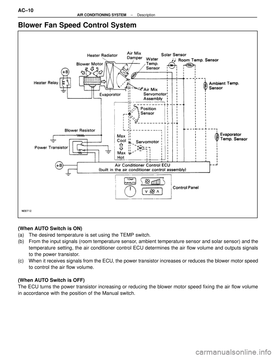
Blower Fan Speed Control System
(When AUTO Switch is ON)
(a) The desired temperature is set using the TEMP switch.
(b) From the input signals (room temperature sensor, ambient temperature sensor and solar sensor) and thetemperature setting, the air conditioner control ECU determines the air flow volume\
and outputs signals
to the power transistor.
(c) When it receives signals from the ECU, the power transistor increases or red\
uces the blower motor speed to control the air flow volume.
(When AUTO Switch is OFF)
The ECU turns the power transistor increasing or reducing the blower mot\
or speed fixing the air flow volume
in accordance with the position of the Manual switch. AC±10
±
AIR CONDITIONING SYSTEM Description
WhereEverybodyKnowsYourName
Page 66 of 4087
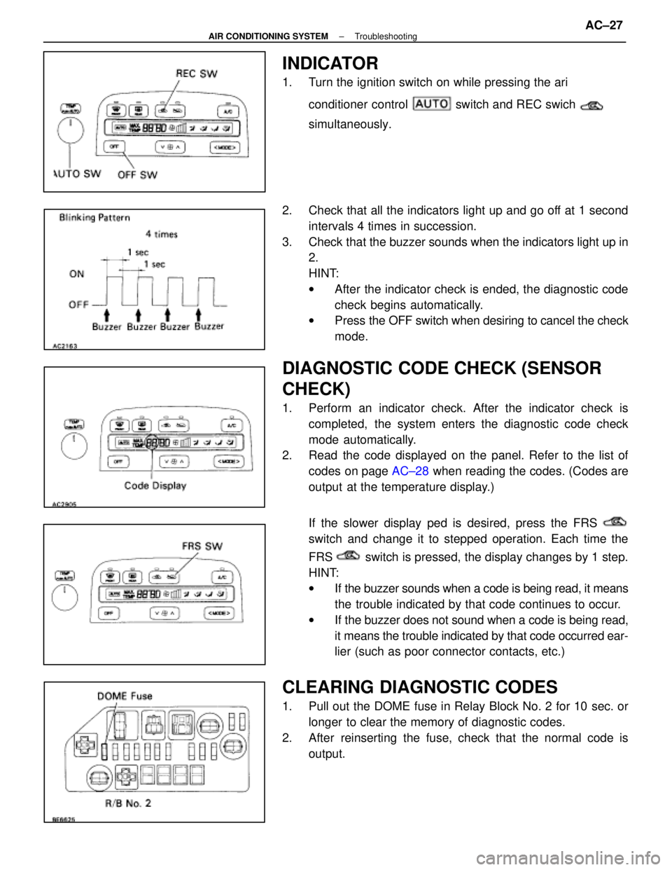
INDICATOR
1. Turn the ignition switch on while pressing the ari conditioner control
switch and REC swich
simultaneously.
2. Check that all the indicators light up and go off at 1 second intervals 4 times in succession.
3. Check that the buzzer sounds when the indicators light up in 2.
HINT:
wAfter the indicator check is ended, the diagnostic code
check begins automatically.
w Press the OFF switch when desiring to cancel the check
mode.
DIAGNOSTIC CODE CHECK (SENSOR
CHECK)
1. Perform an indicator check. After the indicator check is completed, the system enters the diagnostic code check
mode automatically.
2. Read the code displayed on the panel. Refer to the list of
codes on page AC±28 when reading the codes. (Codes are
output at the temperature display.)
If the slower display ped is desired, press the FRS
switch and change it to stepped operation. Each time the
FRS
switch is pressed, the display changes by 1 step.
HINT:
w If the buzzer sounds when a code is being read, it means
the trouble indicated by that code continues to occur.
w If the buzzer does not sound when a code is being read,
it means the trouble indicated by that code occurred ear-
lier (such as poor connector contacts, etc.)
CLEARING DIAGNOSTIC CODES
1. Pull out the DOME fuse in Relay Block No. 2 for 10 sec. or
longer to clear the memory of diagnostic codes.
2. After reinserting the fuse, check that the normal code is output.
±
AIR CONDITIONING SYSTEM TroubleshootingAC±27
WhereEverybodyKnowsYourName