check engine light LEXUS SC400 1991 Service User Guide
[x] Cancel search | Manufacturer: LEXUS, Model Year: 1991, Model line: SC400, Model: LEXUS SC400 1991Pages: 4087, PDF Size: 75.75 MB
Page 537 of 4087

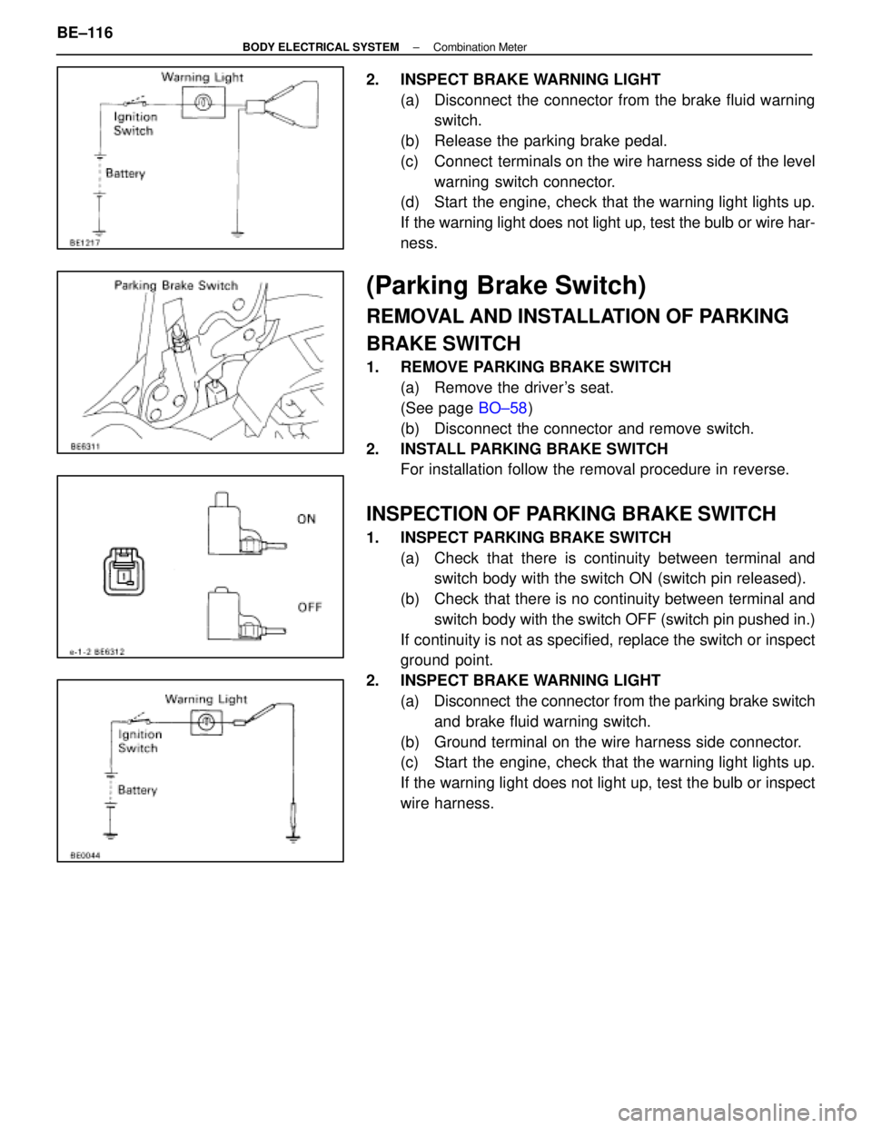
2. INSPECT BRAKE WARNING LIGHT(a) Disconnect the connector from the brake fluid warningswitch.
(b) Release the parking brake pedal.
(c) Connect terminals on the wire harness side of the level warning switch connector.
(d) Start the engine, check that the warning light lights up.
If the warning light does not light up, test the bulb or wire har-
ness.
(Parking Brake Switch)
REMOVAL AND INSTALLATION OF PARKING
BRAKE SWITCH
1. REMOVE PARKING BRAKE SWITCH
(a) Remove the driver's seat.
(See page BO±58)
(b) Disconnect the connector and remove switch.
2. INSTALL PARKING BRAKE SWITCH For installation follow the removal procedure in reverse.
INSPECTION OF PARKING BRAKE SWITCH
1. INSPECT PARKING BRAKE SWITCH
(a) Check that there is continuity between terminal andswitch body with the switch ON (switch pin released).
(b) Check that there is no continuity between terminal and switch body with the switch OFF (switch pin pushed in.)
If continuity is not as specified, replace the switch or inspect
ground point.
2. INSPECT BRAKE WARNING LIGHT (a) Disconnect the connector from the parking brake switchand brake fluid warning switch.
(b) Ground terminal on the wire harness side connector.
(c) Start the engine, check that the warning light lights up.
If the warning light does not light up, test the bulb or inspect
wire harness.
BE±116
±
BODY ELECTRICAL SYSTEM Combination Meter
WhereEverybodyKnowsYourName
Page 538 of 4087

( Coolant Level Warning Switch)
REMOVAL AND INSTALLATION OF COOLANT
LEVEL WARNING SWITCH
1. REMOVE COOLANT LEVEL WARNING SWITCH(a) Disconnect the connector.
(b) Remove the boot.
(c) Using the notches in the head of switch, turn the switchcounterclockwise and remove it.
NOTICE: Do not remove when engine is hot.
2. INSTALL COOLANT LEVEL WARNING SWITCH For installation, follow the removal procedure in reverse.
INSPECTION OF COOLANT LEVEL WARNING
SWITCH
1. INSPECT COOLANT LEVEL WARNING SWITCH(Continuity)
(a) Remove the radiator cap and open the radiator drainclock.
NOTICE: Do not remove when engine is hot.
(b) Drain the coolant about 1 liter. (1.1 US qts, 0.9 lmp. qts)
(c) Check that there is continuity between terminals (float down).
(d) Close radiator drain cock and fill the cooling system with
coolant.
(e) Check that there is no continuity between terminals (float up).
If continuity is not as specified, replace the switch.
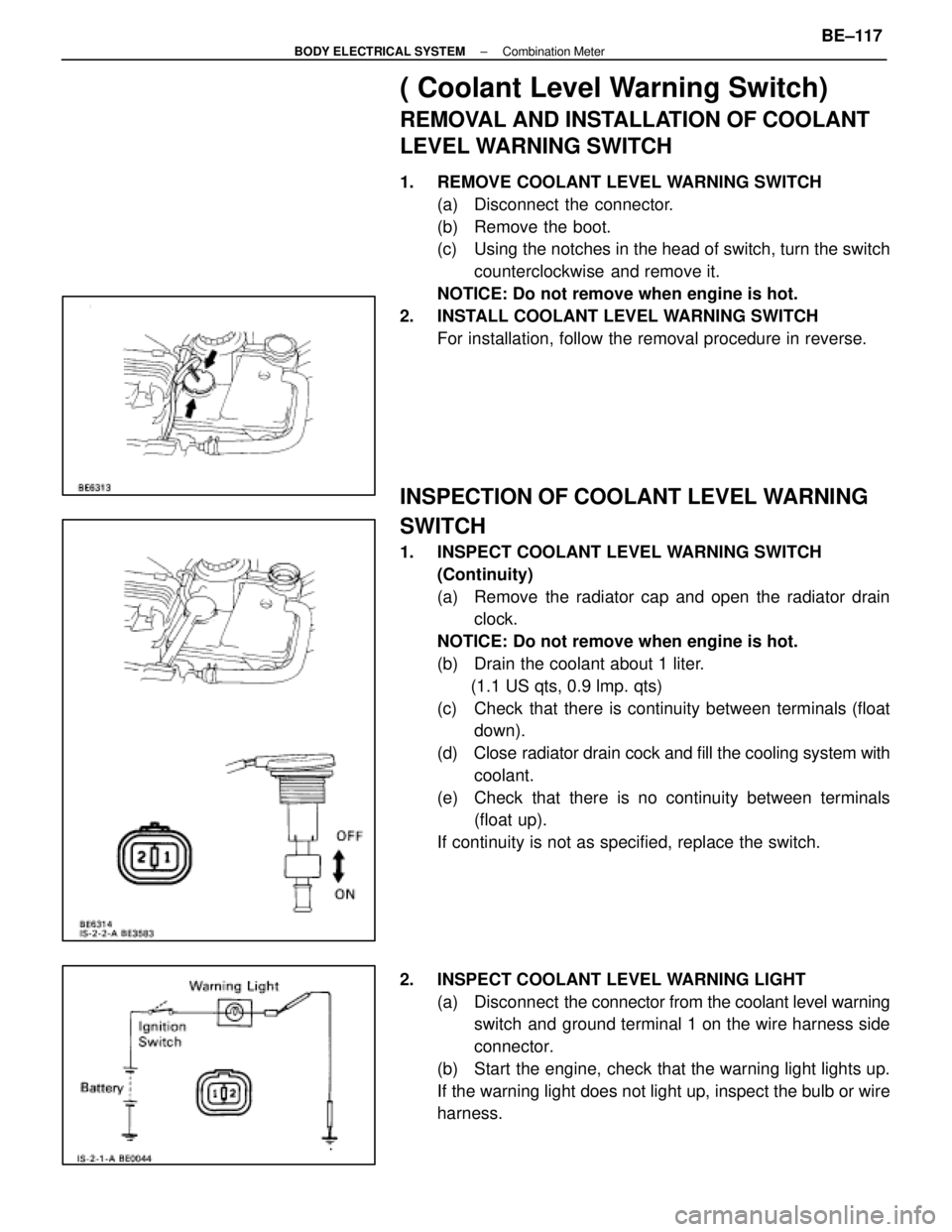
2. INSPECT COOLANT LEVEL WARNING LIGHT (a) Disconnect the connector from the coolant level warning
switch and ground terminal 1 on the wire harness side
connector.
(b) Start the engine, check that the warning light lights up.
If the warning light does not light up, inspect the bulb or wire
harness.
±
BODY ELECTRICAL SYSTEM Combination MeterBE±117
WhereEverybodyKnowsYourName
Page 816 of 4087

Inspection of Power Source Circuit
INSPECTION OF JUNCTION BLOCK NO. 1
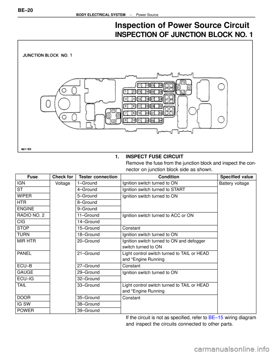
1. INSPECT FUSE CIRCUITRemove the fuse from the junction block and inspect the con-
nector on junction block side as shown.
FuseCheck forTester connectionConditionSpecified value
IGNVoltage1±GroundIgnition switch turned to ONBattery voltage
ST
g
4±GroundIgnition switch turned to START
yg
WIPER5±GroundIgnition switch turned to ON
HTR8±Ground
g
ENGINE9±Ground
RADIO NO. 211±GroundIgnition switch turned to ACC or ON
CIG14±Ground
g
STOP15±GroundConstant
TURN18±GroundIgnition switch turned to ON
MIR HTR20±GroundIgnition switch turned to ON and defogger
switch turned to ON
PANEL21±GroundLight control switch turned to TAIL or HEAD
and *Engine Running
ECU±B27±GroundConstant
GAUGE29±GroundIgnition switch turned to ON
ECU±IG32±Ground
g
TAIL33±GroundLight control switch turned to TAIL or HEAD
and *Engine Running
DOOR35±GroundConstant
IG SW38±Ground
POWER39±Ground
If the circuit is not as specified, refer to BE±15 wiring diagram
and inspect the circuits connected to other parts.
BE±20
±
BODY ELECTRICAL SYSTEM Power Source
WhereEverybodyKnowsYourName
Page 818 of 4087

FuseCheck forTester ConnectionConditionSpecified value
HTRVoltage(15)±GroundConstantBattery voltage
DEF(17)±Ground
DOME(24)±Ground
EFI(26)±Ground
HAZ±HORN(28)±Ground
RADIO NO. 1(30)±Ground
TEL(32)±Ground
ALT±S(34)±Ground
TRAC(36)±Ground
HEAD (RH±LWR)(38)±GroundLight control switch turned to TAIL or
HEAD (LH±LWR)(40)±GroundHEAD and *ENGINE running
HEAD (RH±UPR)(44)±GroundLight control switch turned to HEAD and
HEAD (LH±UPR)(46)±Grounddimmer switch turned to HI or FLASH
If the circuit is not as specified, refer to BE±15 wiring diagram
and inspect the circuits connected to other parts.
2. INSPECT RELAY CIRCUIT Remove the relay from the relay block and inspect the con-
nector on relay block side as shown.
RelayCheck forTester connectionConditionSpecified value
EFIVoltage(4)±GroundConstantBattery voltage
ST(10)±Ground
(11)±Ground
DIM(15)±GroundLight control switch turned to TAIL or HEAD
(16)±Groundand *Engine running
IG2(18)±GroundConstant
HTR(24)±Ground
(25)±Ground
H±LP(28)±Ground
(30)±Ground
DEF(34)±Ground
(35)±Ground
If the circuit is not as specified, refer to BE±15 wiring diagram
and inspect circuits connected to other parts.
BE±22
±
BODY ELECTRICAL SYSTEM Power Source
WhereEverybodyKnowsYourName
Page 846 of 4087

(Canada)
Check forTester connectionConditionSpecified value
ContinuityA4±GroundPassenger's CourtesyOFFNo continuityygy
ONContinuity
A5±GroundIgnition KeyPull offNo continuitygy
Put inContinuity
A6±GroundDriver's CourtesyOFFNo continuityy
ONContinuity
A8±GroundSeat BeltUnfastenContinuity
FastenNo continuity
A10±GroundConstantContinuity
A12±GroundConstantContinuity
B1±GroundPassenger's DoorUnlockContinuityg
LockNo continuity
B2±GroundParking Brake
Switch PositionOFF (Switch pin
pushed in)No continuity
ON (Switch pin re-
leased)Continuity
B3±GroundDriver's DoorUnlockContinuity
LockNo continuity
B7±GroundHeadlight Dimmer
Switch PositionLow Beam or High
BeamNo continuity
FlashContinuity
B8±GroundHeadlight DimmerLow BeamNo continuityg
Switch PositionHigh Beam or FlashContinuity
B10±GroundLight Control SwitchOFFNo continuityg
HEAD or TAILContinuity
B12±GroundConstantContinuity
B13±GroundLight Control SwitchOFF or TAILNo continuityg
HEADContinuity
VoltageA1±GroundConstantVoltageg
A2±GroundConstant*Voltage
A7±GroundIgnition SwitchONVoltageg
LOCK or ACCNo voltage
A9±GroundIgnition SwitchON*Voltageg
LOCK or ACCNo voltage
A11±GroundIgnition SwitchON or ACCVoltageg
LOCKNo voltage
B4±GroundEngineSTOPNo voltageg
RunningVoltage
B11±GroundConstantVoltage
* There is resistance because this circuit is grounded through the bulb.\
If the circuit is as specified, trying replacing the relay with a
new one.
If the circuit is not as specified, refer to BE±35 wiring diagram
and inspect the circuit connected to other parts.
BE±50
±
BODY ELECTRICAL SYSTEM Light System
WhereEverybodyKnowsYourName
Page 857 of 4087

Troubleshooting
Taillight System
You will find the cause of troubles more easily using the table well shown \
below. In this table, the numbers indi-
cate the order priority of the causes in troubles. Check each part in the o\
rder shown. If necessary, replace the
parts.
See page
BE±4,20BE±20 ,57BE±46BE±49BE±62BE±79BE±4,20
±
BE±6
±
Trouble
Part name
TAIL FuseTaillignt Control RelayLight Control SwitchIntegration RelayLight Failure SensorDoor CourtesyGAUGE FuseWire HarnessBulbOther Parts
Taillight does not light. (Headlight does
not light.) 12 3
SA
Taillight does not light. (Headlight is
normal.)12345
US
A
Only one light does not light. (Taillight) 2 1 U
Rear combination light does not light. 213
ªLight Auto Turn±Off Systemº does
not operate. 1432
Taillight does not light. (Headlight is
does not light.) 123
Taillight does not light. (Headlight is
normal.)12345
Only one light does not light. (Taillight) 21
ARear combination light does not light. 213
ANADA
ªLight Auto Turn±Off Systemº does
not operate. 1423
CA
N
Taillight does not light with light control
SW in TAIL123
Taillight does not go out with light
control SW in OFF1324
Headlight and Taillight do not light with
engine running and light control SW in
OFF
213*14
*1:
Alternator
L
Terminal
BE±58±
BODY ELECTRICAL SYSTEM Lighting System
WhereEverybodyKnowsYourName
Page 907 of 4087

ConnectionCheck forTester connectionConditionSpecified value
Turn signalHazard warning switch ONBattery positiveTurn signal
SW andB 16 Ground
Hazard warning switch ONBattery ositive
voltage e 0V
HazardB±16±Ground
IG SW ON and turn signal SW ºLeftºBattery positive
Warning
Si hVoltage
IG SW ON and turn signal SW ºLeftºBattery ositive
voltage e 0V
SwitchVoltage
Hazard warning switch ONBattery positive
B 17 Ground
Hazard warning switch ONBattery ositive
voltage e 0VB±17±Ground
IG SW ON and turn signal SW ºRightºBattery positiveIG SW ON and turn signal SW ºRightºBattery ositive
voltage e 0V
HeadlightLi ht t l SWDimmer SW ºHIº orBattery positiveHeadlight
VoltageB7±GroundLight control SW
ºHEADº
Dimmer SW HI or
ºFlashº
Battery ositive
voltageVoltageB7±GroundºHEADºDimmer SW ºLOºNo voltage
ContinuityB6±GroundLight control SW
º
HEADº
Dimmer SW ºHIº or
ºFlashºContinuityContinuityB6 GroundºHEADºDimmer SW ºLOºNo continuity
IgniterVoltageA9±GroundEngine RunningVoltage
fluctuates
ECT patternVoltageB4 GroundIG SW ON and ECT patternPWRBattery positive voltageECT attern
Select switchVoltageB4±GroundIG SW ON and ECT attern
select SW positionNORMNo voltage
Engine oilOil temperature below approx. 55 5C (131 5F)Continuityg
Level warn-
ing Switch
ContinuityB8±Ground
Oil temperature
above approx. 55 5CON (float up)ContinuitygContinuityB8 Groundabove a rox. 55 C
(131 5F) and SW
positionOFF (float off)No continuity
GAUGE fuseVoltageA1 GroundIgnition switchONBattery positive voltageVoltageA1±GroundIgnition switch
positionLOCK, ACC, STARTNo voltage
Neutral StartVoltageA12±GroundIgnition switch
position
START (ºPº or ºNº
range)Battery positive voltage
switch
VoltageA12 GroundpositionLOCK, ACC, ONNo voltage
ECU±BVoltageC11 GroundIgnition switchONBattery positive voltage
FuseVoltageC11±GroundIgnition switch
positionLOCK, ACC, STARTNo voltage
Rheostat
Li ht t l
ON (Rheostat knob
t d itiBtt ltLight control
VolumeLight control SWturned any position
except fully clock-
Battery voltage or
5V or moreVolume
VoltageA2±Ground
g
HEAD or TAIL and
rheostat volume
except fully clock-
wise)5V or more
VoltageA2 Groundrheostat volume
knob positionOFF (Rheostat knob)
turned fully clockNo voltageknob ositionturned fully clock-
wise)No voltage
GroundA8±GroundConstantContinuity
ContinuityA10±GroundConstantContinuityContinuityA22±GroundConstantContinuity
A23±GroundConstantContinuity
*1 Jack up the vehicle.*2 Shift lever position is ºPº range.
If circuit is not as specified, refer to BE±100 wiring diagrams
and inspect the circuits connected to other parts.
BE±108
±
BODY ELECTRICAL SYSTEM Combination Meter
WhereEverybodyKnowsYourName
Page 984 of 4087

CHECK AND ADJUSTMENT
BR0EC±07
BRAKE PEDAL CHECK AND
ADJUSTMENT
1. CHECK THAT PEDAL HEIGHT IS CORRECT
Pedal height from asphalt sheet:150.4±160.4 mm (5.92±6.31 in.)
If the pedal height is incorrect, adjust it.
2. IF NECESSARY, ADJUST PEDAL HEIGHT
(a) Disconnect the connector from the stop light switch.
(b) Loosen the stop light switch lock nut and remove the stop light switch.
(c) Loosen the push rod lock nut.
(d) Adjust the pedal height by turning the pedal push rod.
(e) Tighten the push rod lock nut.
Torque: 25 N Vm (260 kgf Vcm, 19 ft Vlbf)
(f) Install the stop light switch and turn it until it lightly contacts
the pedal stopper.
(g) Turn the stop light switch back one turn.
(h) Check the clearance (A) between stop light switch and pedal.
Clearance:
0.5±2.4 mm (0.02±0.09 in.)
(i) Tighten the stop light switch lock nut.
(j) Connect the connector to the stop light switch.
(k) Check that the stop lights come on when the brake pedal isdepressed, and go off when the brake pedal is released.
(l) After adjusting the pedal height, check the pedal free±play.
HINT: If clearance (A) between the stop light switch and the
brake pedal stopper has been adjusted correctly, the pedal
freeplay will meet the specifications.
3. CHECK THAT PEDAL FREEPLAY IS CORRECT, AS SHOWN
(a) Stop the engine and depress the brake pedal several times until there is no more vacuum left in the booster.
(b) Push in the pedal by hand until the beginning of the second point of resistance is felt, then measure the distance, as
shown.
Pedal freeplay:
1±6 mm (0.04±0.24 in.)
If incorrect, check the stop light switch clearance. And if the
clearance is OK, then troubleshoot the brake system.
HINT: The freeplay to the first point of resistance is due to the
play between the clevis and pin. It is 1±3 mm (0.04±0.12 in.)
on the pedal.
±
BRAKE SYSTEM CHECK AND ADJUSTMENTBR±7
WhereEverybodyKnowsYourName
Page 985 of 4087

4. CHECK THAT PEDAL RESERVE DISTANCE IS CORRECT,
AS SHOWN
Release the parking brake.
With the engine running, depress the pedal and measure the
pedal reserve distance, as shown.
Pedal reserve distance at 490 N (50 kgf, 110.2 lbf):
More than 89 mm (3.50 in.)
If the reserve distance is incorrect, troubleshoot the brake
system.
BRAKE BOOSTER OPERATIONAL TEST
BR03P±0B
1. OPERATING CHECK
(a) Depress the bake pedal several times with the engine off and
check that there is no change in the pedal reserve distance.
(b) Depress the brake pedal and start the engine. If the pedal goes down slightly, operation is normal.
2. AIR TIGHTNESS CHECK
(a) Start the engine and stop it after 1 or 2 minutes. Depress the brake pedal several times slowly. If the pedal goes down the
farthest the 1st time, but gradually rises after the 2nd or 3rd
time, the booster is air tight.
(b) Depress the brake pedal while the engine is running, and stop the engine with the pedal depressed. If there is no
change in the pedal reserve travel after holding the pedal for
30 seconds, the booster is air tight.
BRAKE SYSTEM BLEEDING
BR0ED±04
HINT: If any work is done on the brake system or if air in the
brake lines is suspected, bleed the system of air.
NOTICE: Do not let brake fluid remain on painted sur-
faces. Wash it off immediately.
1. REMOVE RESERVOIR CAP Turn the reservoir cap to the ªopenº side and remove it.
2. FILL RESERVOIR WITH BRAKE FLUID
Fluid: SAE J1703 or FMVSS NO.116DOT3
BR±8±
BRAKE SYSTEM CHECK AND ADJUSTMENT
WhereEverybodyKnowsYourName
Page 1049 of 4087

SPEED SENSOR SIGNAL CHECK
1. Turn the ignition switch to OFF.
2. Using SST, connect terminals Ts and E1 of DLC1.SST 09843±18020
3. Start the engine.
4. Check that the ABS warning light blinks. HINT: If the ABS warning light does not blink, inspect the ABS
warning light circuit (see page BR±144).
5. Drive vehicle straight forward. HINT: Drive vehicle faster than 45 km/h (28 mph) for several
seconds.
6. Stop the vehicle.
7. Using SST, connect terminals Tc and E1 of DLC1.
SST 09843±18020
8. Read the number of blinks of the ABS warning light. HINT: See the list of diagnosis trouble codes shown on the
next page.
If every sensor is normal, a normal code is output (A cycle of
0.25 sec. on and 0.25 sec. OFF is repeated).
If 2 or more malfunction are indicated at the same time, the
lowest numbered code will be displayed 1st.
9. After performing the check, disconnect terminals Ts and E1,Tc and E1 of DLC1, and ignition switch turned off.
BR±80
±
BRAKE SYSTEM ANTI±LOCK BRAKE SYSTEM (ABS)
WhereEverybodyKnowsYourName