drain bolt LEXUS SC400 1991 Service User Guide
[x] Cancel search | Manufacturer: LEXUS, Model Year: 1991, Model line: SC400, Model: LEXUS SC400 1991Pages: 4087, PDF Size: 75.75 MB
Page 1390 of 4087

EG21S±02
VALVE CLEARANCE INSPECTION AND
ADJUSTMENT
HINT: Inspect and adjust the valve clearance when the en-
gine is cold.
1. DISCONNECT NEGATIVE TERMINAL CABLE FROM BATTERY
CAUTION: Work must be started after 90 seconds from
the time the ignition switch is turned to the ªLOCKº posi-
tion and the negative (±) terminal cable is disconnected
from the battery.
2. DRAIN ENGINE COOLANT
3. REMOVE THROTTLE BODY COVER
(a) Disconnect the EVAP hose from the hose clamp.
(b) Remove the cap nut.
(c) Loosen the 2 bolts, and remove the hose clamp and throttle
body cover.
4. DISCONNECT CONTROL CABLES TO THROTTLE BODY Disconnect the following cables:
(1) Accelerator cable
(2) Transmission throttle control cable
(3) Cruise control actuator cable
5. REMOVE INTAKE AIR CONNECTOR
(a) Disconnect the following hoses: (1) Air hose from IAC valve
(2) Air hose (from air control valve on PS pump) from intake
air connector
EG±14
±
1UZ±FE ENGINE ENGINE MECHANICAL
WhereEverybodyKnowsYourName
Page 1422 of 4087

EG21P±02
TIMING BELT REMOVAL
(See Components for Removal and Installation)
1. REMOVE BATTERY CAUTION: Work must be started after 90 seconds from
the time the ignition switch is turned to the ªLOCKº posi-
tion and the negative (±) terminal cable is disconnected
from the battery.
2. REMOVE ENGINE UNDER COVER
3. DRAIN ENGINE COOLANT
4. REMOVE DRIVE BELT
Loosen the drive belt tension by turning the drive belt tension-
er counterclockwise, and remove the drive belt.
HINT: The pulley bolt for the drive belt tensioner has a left±
hand thread.
5. REMOVE RADIATOR RESERVOIR TANK
(a) Disconnect the coolant level sensor connector.
(b) Disconnect the following hoses: (1) Reservoir hose from water inlet housing
(2) Reservoir hose from radiator
(c) Remove the 2 bolts and reservoir tank bracket.
(d) Remove the bolt holding the reservoir tank to the radiator.
(e) Disconnect the reservoir tank from the reservoir tank bracket,
and remove the reservoir tank.
6. REMOVE RADIATOR ASSEMBLY
(a) Disconnect the ECT sensor connector (for cooling fan).
(b) Disconnect the ECT sensor wire clamp from the radiator fan shroud.
EG±46
±
1UZ±FE ENGINE ENGINE MECHANICAL
WhereEverybodyKnowsYourName
Page 1515 of 4087

ENGINE REMOVAL
EG24W±02
(See Components for Engine Removal and Installation)
1. REMOVE BATTERYCAUTION: Work must be started after 90 seconds from
the time the ignition switch is turned to the ªLOCKº posi-
tion and the negative (±) terminal cable is disconnected
from the battery.
2. REMOVE HOOD
3. REMOVE ENGINE UNDER COVER
4. DRAIN ENGINE COOLANT
5. DRAIN ENGINE OIL
6. REMOVE DRIVE BELT Loosen the drive belt tension by turning the drive belt tension-
er counterclockwise, and remove the drive belt.
HINT: The pulley bolt for the drive belt tensioner has a left±
hand thread.
±
1UZ±FE ENGINE ENGINE MECHANICALEG±139
WhereEverybodyKnowsYourName
Page 1583 of 4087
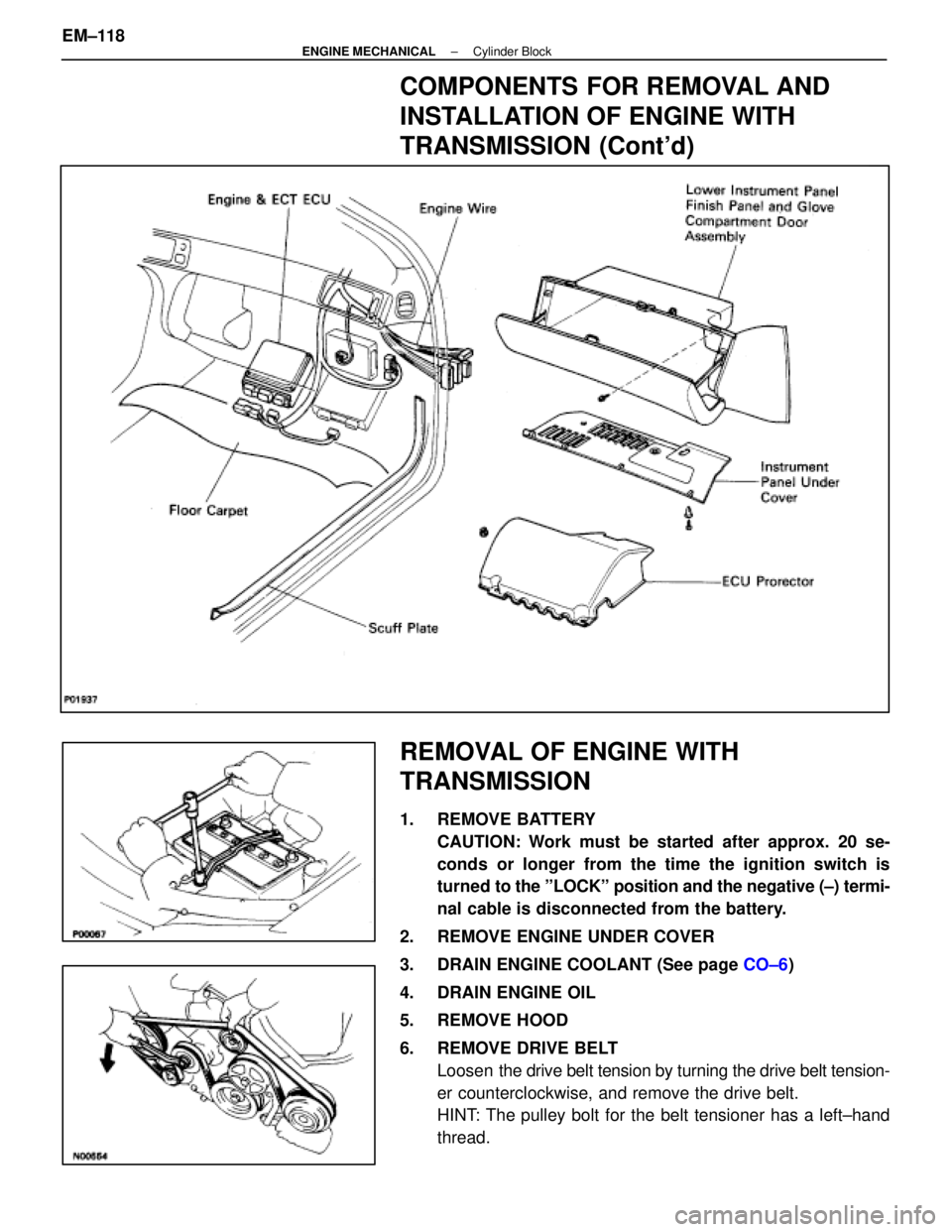
COMPONENTS FOR REMOVAL AND
INSTALLATION OF ENGINE WITH
TRANSMISSION (Cont'd)
REMOVAL OF ENGINE WITH
TRANSMISSION
1. REMOVE BATTERYCAUTION: Work must be started after approx. 20 se-
conds or longer from the time the ignition switch is
turned to the ºLOCKº position and the negative (±) termi-
nal cable is disconnected from the battery.
2. REMOVE ENGINE UNDER COVER
3. DRAIN ENGINE COOLANT (See page CO±6)
4. DRAIN ENGINE OIL
5. REMOVE HOOD
6. REMOVE DRIVE BELT Loosen the drive belt tension by turning the drive belt tension-
er counterclockwise, and remove the drive belt.
HINT: The pulley bolt for the belt tensioner has a left±hand
thread.
EM±118
±
ENGINE MECHANICAL Cylinder Block
WhereEverybodyKnowsYourName
Page 1642 of 4087
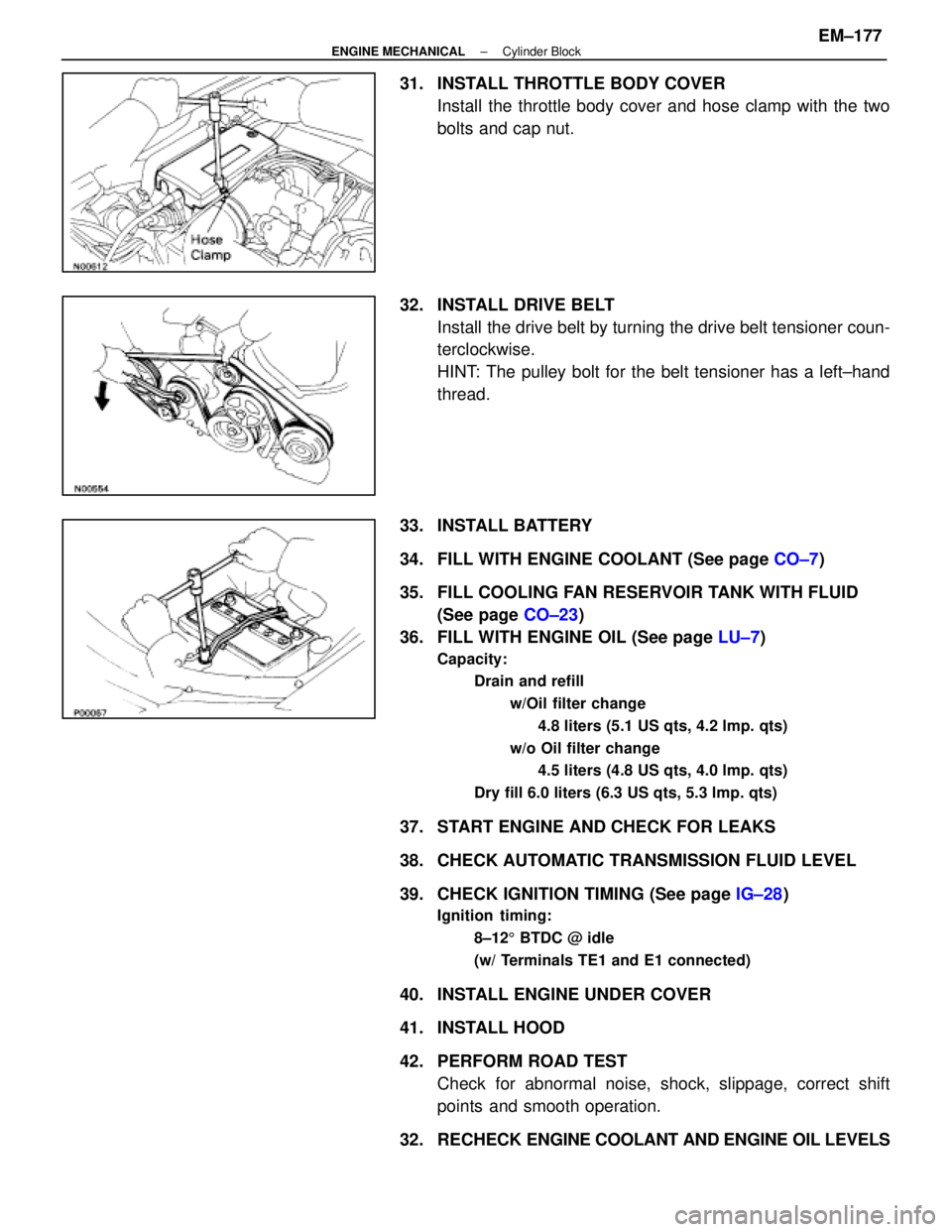
31. INSTALL THROTTLE BODY COVERInstall the throttle body cover and hose clamp with the two
bolts and cap nut.
32. INSTALL DRIVE BELT Install the drive belt by turning the drive belt tensioner coun-
terclockwise.
HINT: The pulley bolt for the belt tensioner has a left±hand
thread.
33. INSTALL BATTERY
34. FILL WITH ENGINE COOLANT (See page CO±7)
35. FILL COOLING FAN RESERVOIR TANK WITH FLUID (See page CO±23)
36. FILL WITH ENGINE OIL (See page LU±7)
Capacity:
Drain and refill
w/Oil filter change4.8 liters (5.1 US qts, 4.2 lmp. qts)
w/o Oil filter change 4.5 liters (4.8 US qts, 4.0 lmp. qts)
Dry fill 6.0 liters (6.3 US qts, 5.3 lmp. qts)
37. START ENGINE AND CHECK FOR LEAKS
38. CHECK AUTOMATIC TRANSMISSION FLUID LEVEL
39. CHECK IGNITION TIMING (See page IG±28)
Ignition timing:
8±125 BTDC @ idle
(w/ Terminals TE1 and E1 connected)
40. INSTALL ENGINE UNDER COVER
41. INSTALL HOOD
42. PERFORM ROAD TEST Check for abnormal noise, shock, slippage, correct shift
points and smooth operation.
32. RECHECK ENGINE COOLANT AND ENGINE OIL LEVELS
±
ENGINE MECHANICAL Cylinder BlockEM±177
WhereEverybodyKnowsYourName
Page 1670 of 4087
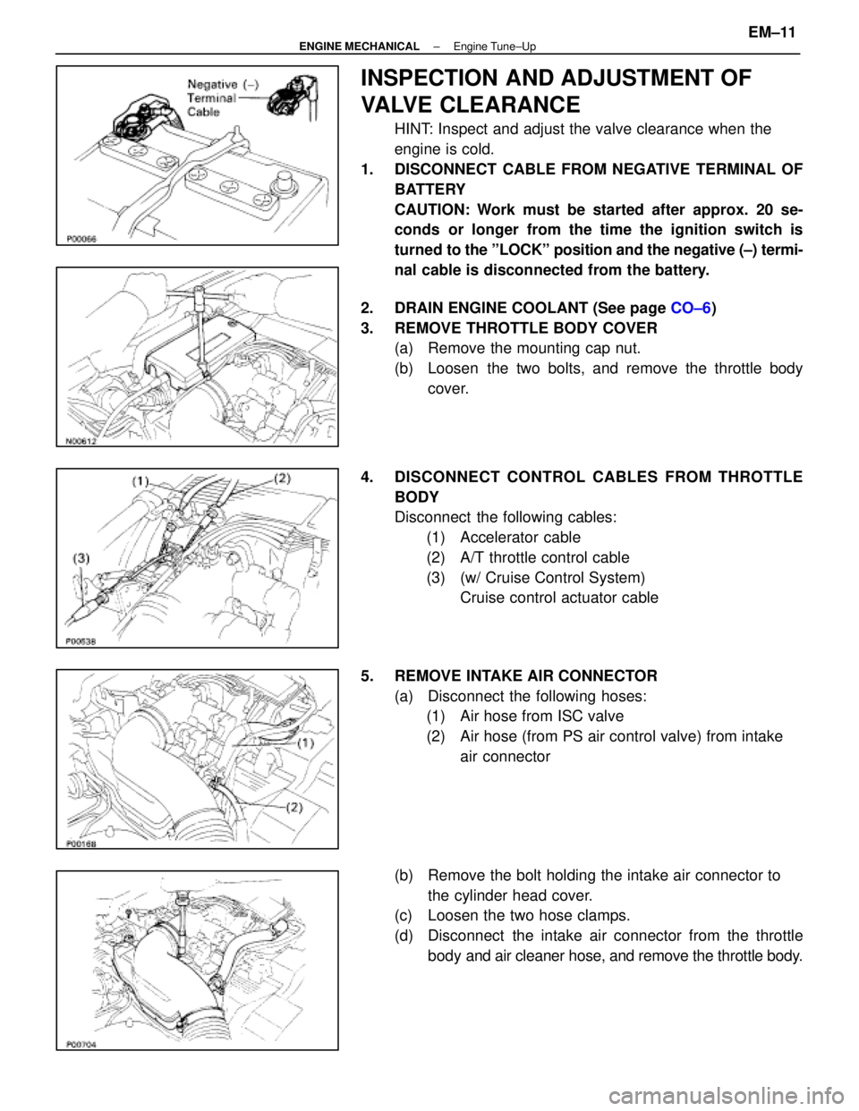
INSPECTION AND ADJUSTMENT OF
VALVE CLEARANCE
HINT: Inspect and adjust the valve clearance when the
engine is cold.
1. DISCONNECT CABLE FROM NEGATIVE TERMINAL OF BATTERY
CAUTION: Work must be started after approx. 20 se-
conds or longer from the time the ignition switch is
turned to the ºLOCKº position and the negative (±) termi-
nal cable is disconnected from the battery.
2. DRAIN ENGINE COOLANT (See page CO±6)
3. REMOVE THROTTLE BODY COVER (a) Remove the mounting cap nut.
(b) Loosen the two bolts, and remove the throttle body
cover.
4. DISCONNECT CONTROL CABLES FROM THROTTLE BODY
Disconnect the following cables:(1) Accelerator cable
(2) A/T throttle control cable
(3) (w/ Cruise Control System) Cruise control actuator cable
5. REMOVE INTAKE AIR CONNECTOR (a) Disconnect the following hoses:(1) Air hose from ISC valve
(2) Air hose (from PS air control valve) from intake
air connector
(b) Remove the bolt holding the intake air connector to the cylinder head cover.
(c) Loosen the two hose clamps.
(d) Disconnect the intake air connector from the throttle
body and air cleaner hose, and remove the throttle body.
±
ENGINE MECHANICAL Engine Tune±UpEM±11
WhereEverybodyKnowsYourName
Page 1708 of 4087
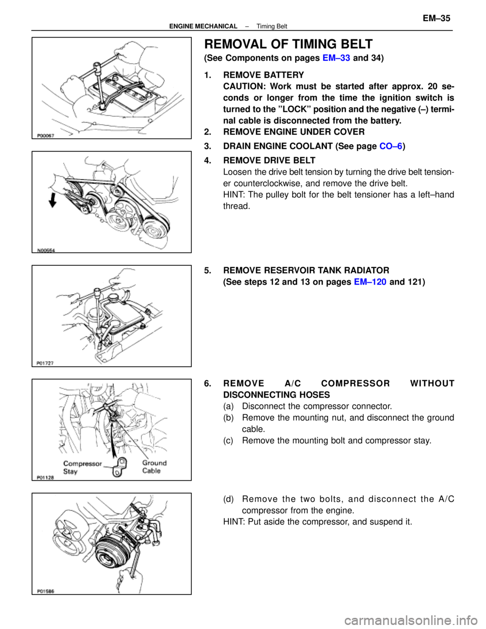
REMOVAL OF TIMING BELT
(See Components on pages EM±33 and 34)
1. REMOVE BATTERY CAUTION: Work must be started after approx. 20 se-
conds or longer from the time the ignition switch is
turned to the ºLOCKº position and the negative (±) termi-
nal cable is disconnected from the battery.
2. REMOVE ENGINE UNDER COVER
3. DRAIN ENGINE COOLANT (See page CO±6)
4. REMOVE DRIVE BELT Loosen the drive belt tension by turning the drive belt tension-
er counterclockwise, and remove the drive belt.
HINT: The pulley bolt for the belt tensioner has a left±hand
thread.
5. REMOVE RESERVOIR TANK RADIATOR (See steps 12 and 13 on pages EM±120 and 121)
6. REMOVE A/C COMPRESSOR WITHOUT DISCONNECTING HOSES
(a) Disconnect the compressor connector.
(b) Remove the mounting nut, and disconnect the groundcable.
(c) Remove the mounting bolt and compressor stay.
(d) R e m o v e t h e t w o b o l t s , a n d d i s c onnect the A/C
compressor from the engine.
HINT: Put aside the compressor, and suspend it.
±
ENGINE MECHANICAL Timing BeltEM±35
WhereEverybodyKnowsYourName
Page 1909 of 4087
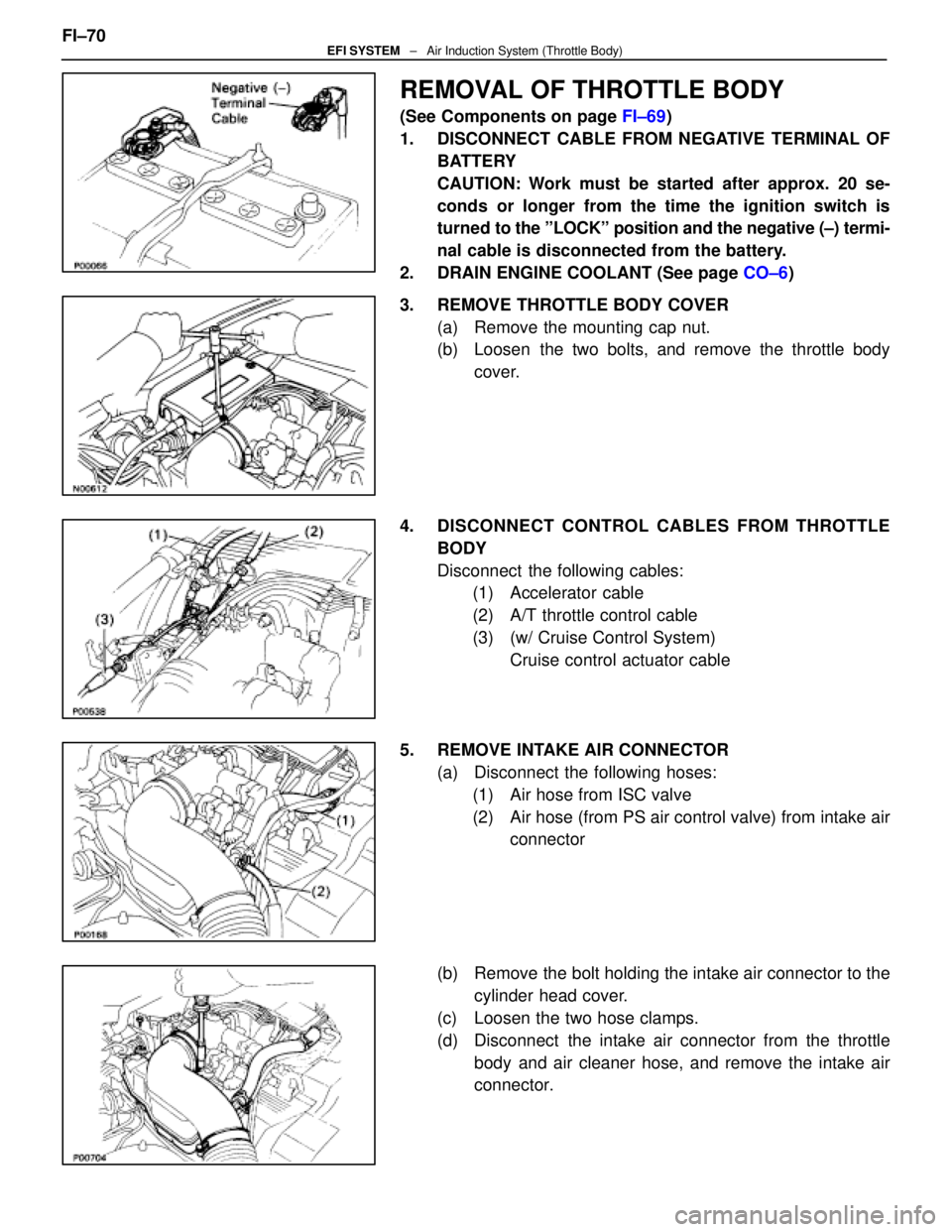
REMOVAL OF THROTTLE BODY
(See Components on page FI±69)
1. DISCONNECT CABLE FROM NEGATIVE TERMINAL OF BATTERY
CAUTION: Work must be started after approx. 20 se-
conds or longer from the time the ignition switch is
turned to the ºLOCKº position and the negative (±) termi-
nal cable is disconnected from the battery.
2. DRAIN ENGINE COOLANT (See page CO±6)
3. REMOVE THROTTLE BODY COVER (a) Remove the mounting cap nut.
(b) Loosen the two bolts, and remove the throttle bodycover.
4. DISCONNECT CONTROL CABLES FROM THROTTLE BODY
Disconnect the following cables:(1) Accelerator cable
(2) A/T throttle control cable
(3) (w/ Cruise Control System)
Cruise control actuator cable
5. REMOVE INTAKE AIR CONNECTOR (a) Disconnect the following hoses:(1) Air hose from ISC valve
(2) Air hose (from PS air control valve) from intake air connector
(b) Remove the bolt holding the intake air connector to the cylinder head cover.
(c) Loosen the two hose clamps.
(d) Disconnect the intake air connector from the throttle body and air cleaner hose, and remove the intake air
connector.
FI±70
EFI SYSTEM
± Air Induction System (Throttle Body)
WhereEverybodyKnowsYourName
Page 1958 of 4087
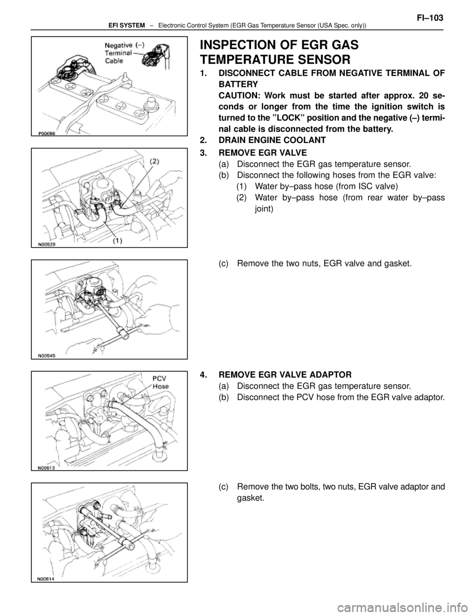
INSPECTION OF EGR GAS
TEMPERATURE SENSOR
1. DISCONNECT CABLE FROM NEGATIVE TERMINAL OFBATTERY
CAUTION: Work must be started after approx. 20 se-
conds or longer from the time the ignition switch is
turned to the ºLOCKº position and the negative (±) termi-
nal cable is disconnected from the battery.
2. DRAIN ENGINE COOLANT
3. REMOVE EGR VALVE (a) Disconnect the EGR gas temperature sensor.
(b) Disconnect the following hoses from the EGR valve:(1) Water by±pass hose (from ISC valve)
(2) Water by±pass hose (from rear water by±pass joint)
(c) Remove the two nuts, EGR valve and gasket.
4. REMOVE EGR VALVE ADAPTOR (a) Disconnect the EGR gas temperature sensor.
(b) Disconnect the PCV hose from the EGR valve adaptor.
(c) Remove the two bolts, two nuts, EGR valve adaptor andgasket. FI±103
EFI SYSTEM
± Electronic Control System (EGR Gas Temperature Sensor (USA Spec. only))
WhereEverybodyKnowsYourName
Page 2048 of 4087
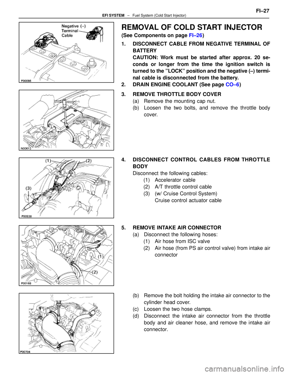
REMOVAL OF COLD START INJECTOR
(See Components on page FI±26)
1. DISCONNECT CABLE FROM NEGATIVE TERMINAL OF BATTERY
CAUTION: Work must be started after approx. 20 se-
conds or longer from the time the ignition switch is
turned to the ºLOCKº position and the negative (±) termi-
nal cable is disconnected from the battery.
2. DRAIN ENGINE COOLANT (See page CO±6)
3. REMOVE THROTTLE BODY COVER (a) Remove the mounting cap nut.
(b) Loosen the two bolts, and remove the throttle bodycover.
4. DISCONNECT CONTROL CABLES FROM THROTTLE BODY
Disconnect the following cables:(1) Accelerator cable
(2) A/T throttle control cable
(3) (w/ Cruise Control System)
Cruise control actuator cable
5. REMOVE INTAKE AIR CONNECTOR (a) Disconnect the following hoses:(1) Air hose from ISC valve
(2) Air hose (from PS air control valve) from intake air connector
(b) Remove the bolt holding the intake air connector to the cylinder head cover.
(c) Loosen the two hose clamps.
(d) Disconnect the intake air connector from the throttle body and air cleaner hose, and remove the intake air
connector. FI±27
EFI SYSTEM
± Fuel System (Cold Start Injector)
WhereEverybodyKnowsYourName